
FEA Roundup: Design, Simulation And Analysis Converge
New modeling and analysis software products increase the accessibility and reliability of finite element analysis data.


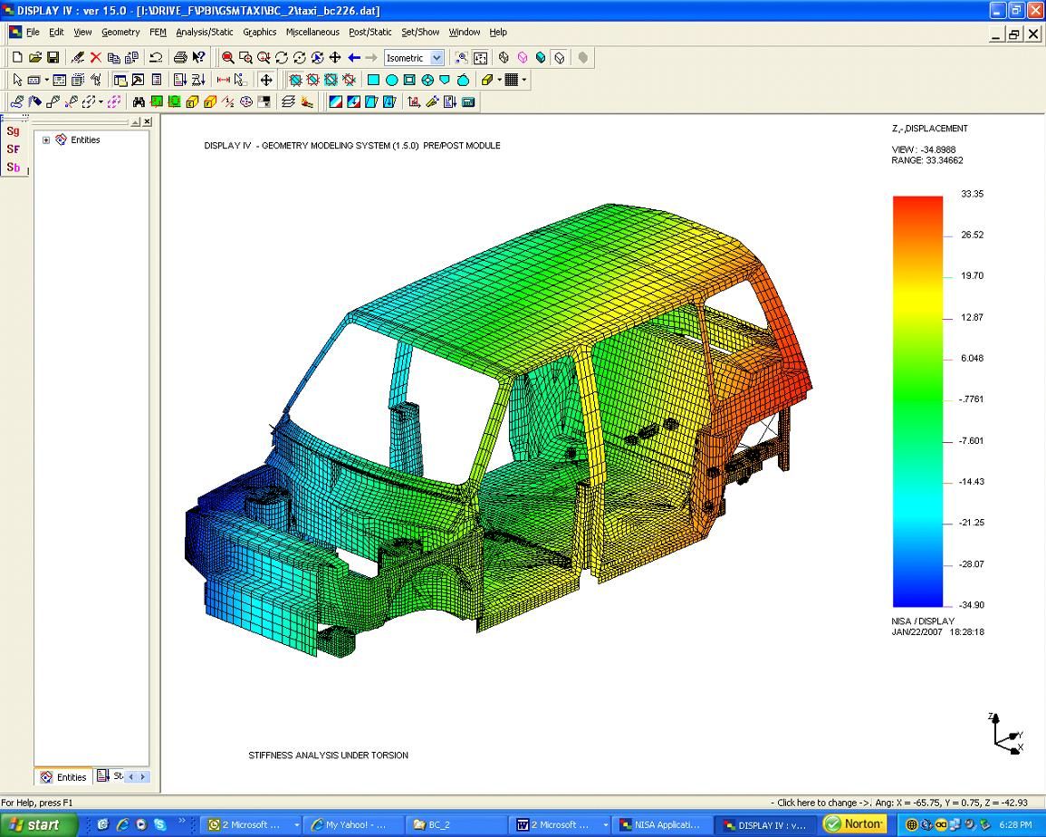
NISA II/COMPOSITE, from Cranes Software Inc., was used to model this two-piece composite shell for an otherwise metal body designed for a low-volume production SUV. Source: Cranes Software Inc.
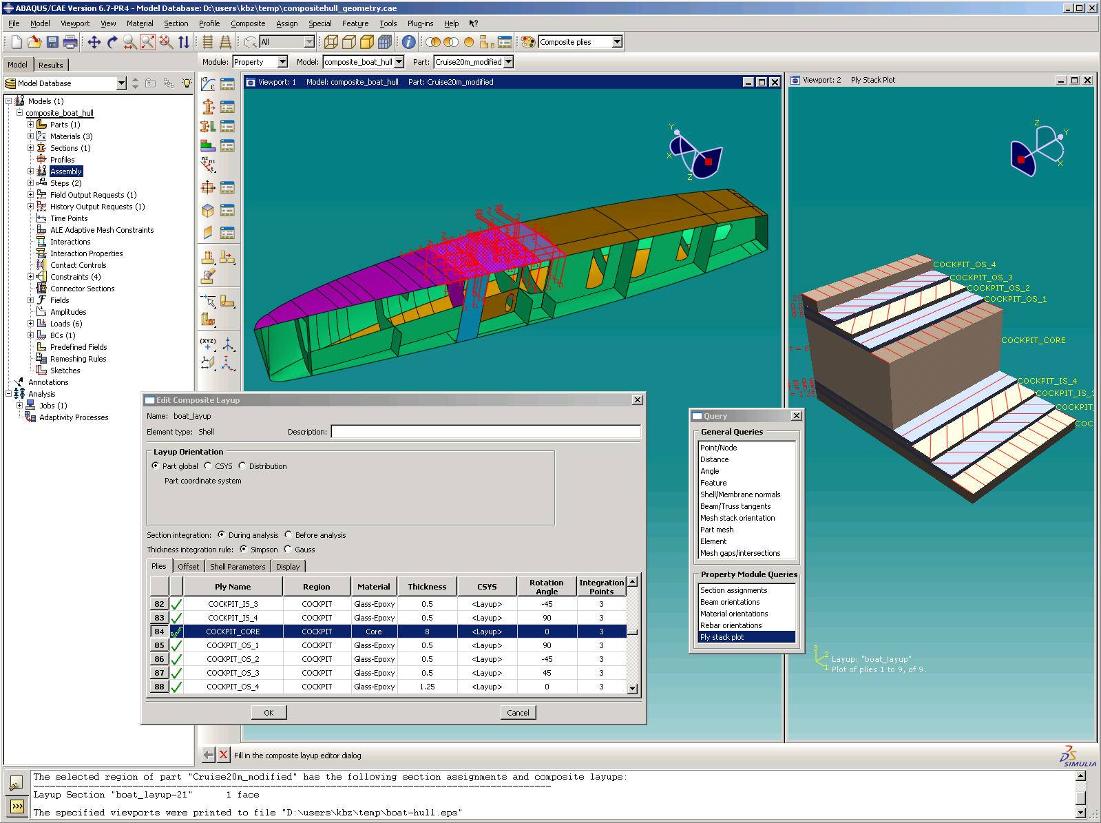
The newest version of ABAQUS offers transfer of legacy data, scripting support for customers' standalone programs, and automated meshing and layup/ply definition tools. Source: ABAQUS Inc.

Source: The dome on the Southern Astrophysical Research (SOAR) telescope in the Chilean Andes consists of a metal frame overlaid with glass fiber composite panels. NEiNastran FEA software from Noran Engineering was used to model and assess the structure's integrity and load-bearing capacity. Source: Noran Engineering
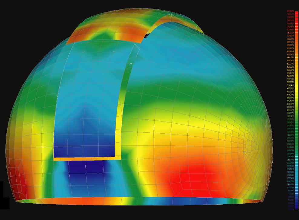
An FEA image of the SOAR dome. Source: Noran Engineering
Laminate tools, from Anaglyph, works between the pre-processor and the FEA program to help designers model and manage material usage, ply shape and coverage, fabric straining, layer thickness, fiber orientation, stacking sequence, offsets, thickness distribution and fabric properties. Once the layup is built in Laminate Tools, it can be exported for FEA in either ANSYS or NASTRAN format. Source: Anaglyph
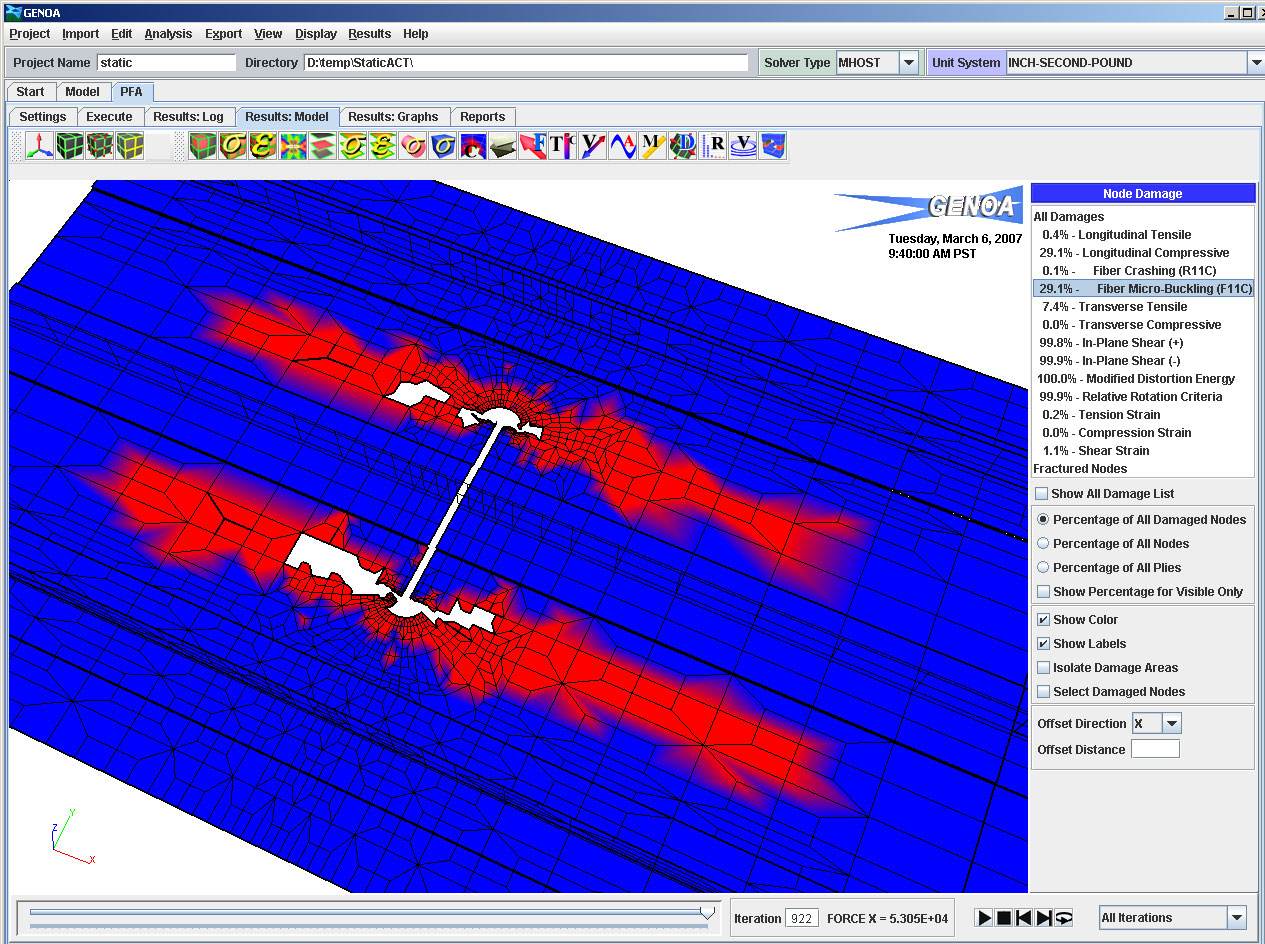
GENOA, from Alpha STAR Corp., focuses on modeling fatigue and material failure, emphasizing micro-mechanics analysis. It takes a progressive failure analysis approach and performs damage tracking fracture analysis and optimization. Source: Alpha STAR Corp.
The ability to predict, in the design stage, how a product will perform in its operating environment is not only an invaluable aid but, in an increasingly competitive marketplace, an economic necessity as well. Today, finite element analysis (FEA) software can provide reliable design feedback once impossible short of producing and testing a series of prototypes.
FEA is an iterative process that integrates a variety of discreet functions to help the user do analysis. The first function is part or product design. When complete, a design can be exported to a pre-processor, software that acts as the user interface for FEA and provides the graphical tools to construct a finite element model – a geometrical representation of the prospective component. This model usually consists of a meshed pattern that breaks the design up into small, manageable nodes for the analysis (see “The ABCs of FEA,” CT October 2006, p. 26). Material data for model construction usually comes from a third party materials database (e.g., MatWeb, Materiality, IDAC) and is easily integrated into most FEA programs. The analysis itself is performed by an FEA solver, the input for which is the mesh data from the pre-processor. Data gleaned from virtual testing of the modeled component in the solver then are returned for post-processing and graphical representation.


Today, FEA is no longer the exclusive preserve of the engineer. Increasingly user-friendly software is making FEA more accessible to designers without a strong engineering background. For designers, software developers believe a thorough understanding of FEA soon will be essential. “You will see more and more of the analysis done in the CAD and design environment,” says Olivier Guillermin, director of product and market strategy for VISTAGY Inc. (Waltham, Mass.), adding that although design and analysis groups haven't always interacted well, it's clear that they will be forced to cooperate more. “Most analysis, today, is done by experts – not everyone understands iterative use,” notes Sandor Becz, aerospace industry solutions manager for ABAQUS (Providence, R.I.). But that will change. “Analysis of composites will be pushed earlier in the design cycle,” he explains. “You don’t want to under-design or over-design, and FEA can help a designer with that.”
Olivier Morisot, marketing manager at ESI Group (Rungis, France) points out that economics alone justify FEA’s use in design: “You need to make design changes as early as possible, because changes later in the development process are much more expensive. A simulator brings more value to the table because it allows you to see and do things that are otherwise very difficult.” Morisot adds that although basic FEA actually can be done within many of today’s CAD packages, the unique challenges involved in ply layup and draping still require more robust analysis software.
Emerging FEA product development, therefore, is focusing on two themes: 1) adapting the user interface environment to increase ease of use without compromising the power and sophistication of FEA; and 2) continuing to integrate composites-specific functionality so that FEA programs can fully and thoroughly address the complexities of the composites manufacturing process. The following surveys recent software offerings designed to meet these goals.
Pre-/post-processor
Because user access to the FEA solver and its data is granted through the pre- and post-processor, these software modules are critical to an engineer’s analysis efforts. HyperMesh, a pre-/post-processor from Altair Engineering Inc. (Troy, Mich.), was developed to import design data directly from popular CAD programs such as CATIA, I-DEAS, Pro-E, Unigraphics, ACIS, IGES and Parasolid, and offers a variety of tools to generate and then “clean up” finite element models, eliminating surface gaps, overlaps, misalignments and unwanted holes in the mesh. Meshed images can be generated for 2-D and 3-D models, and an automeshing module enables the user to adjust mesh parameters for each surface or surface edge. FEA solver support includes ABAQUS, Nastran, ANSYS and Moldflow/C-Mold; additional solvers can be accommodated with an export template language.
Structural, fatigue, damage analysis
Among the biggest challenges in the FEA world is the modeling and prediction of composite failure. ABAQUS’ Becz, emphasizes that the layered nature of composites makes it easy for damage to propagate undetected. For example, a low-impact collision that could result in no or barely visible impact damage (BVID) to a part’s exterior surface, yet cause subsurface fiber damage, cracks, delamination or debonding. His company’s ABAQUS software suite is designed to address a range of analytical functions with an emphasis, for composites designers, on cycle loading, stress and impact damage modeling. Notable is ABAQUS/CAE, which provides a Windows-based GUI and allows the user to pull in CAD drawings for mesh generation and analysis. A variety of tools within ABAQUS enable assessment of high-speed impact damage, BVID caused by low-speed impacts, debonding and delamination as well as crack growth and crack-growth-to-failure. The latter is addressed by a module called Virtual Crack Closure Technique (VCCT), which was developed with The Boeing Co. (Seattle, Wash.) to enable engineers to identify the load at which a crack begins to grow and to simulate its subsequent growth.
Like many FEA developers, ABAQUS also offers a product that bundles an established CAD program with an FEA tool. ABAQUS/CATIA allows the transfer of drawings directly from CATIA (Dassault Systemes, Paris, France), to ABAQUS, effectively closing the design-and-analysis loop and, as a result, providing designers nearly instant feedback.
The newest version of ABAQUS, due out this spring, includes tools for easy transfer of legacy data, scripting support for customers’ standalone programs, and automated meshing and lay-up/ply definition tools. The new software is said to offer more detailed analysis for damage and failure models. It also has improved BVID capabilities and offers greater ease-of-use for advanced composites simulations.
GENOA, developed by Alpha STAR Corp. (Long Beach, Calif.), simulates physical testing of advanced composite and metal structures, taking a progressive failure analysis (PFA) approach. The program focuses on failure analysis at the micromechanics level and performs damage tracking, fracture analysis, and optimization and reliability algorithms. FEA can be done within GENOA or through a commercial FEA package. GENOA uses a building-block process that emulates structural testing by performing progressive failure analyses at the coupon, element, component and full-scale article levels. The software simulates and analyzes advanced materials and structures, including configuration-specific failure mechanisms, such as metals, polymeric matrix composites, ceramics, ceramic matrix composites, honeycomb sandwich, filament winding and adhesives. Architectures like 2-D and 3-D weave and braid material systems also can be analyzed.
A recent upgrade to GENOA includes a new software tool for microcrack density evaluation and multistage fatigue simulation. Microcrack density analysis enables prediction of the deterioration of mechanical properties in a composite matrix as microcracks occur and grow. Alpha STAR maintains that its microcrack density computations were validated by comparing GENOA results to measured residual mechanical properties of carbon fiber polymeric composites at temperatures varying from -432ºF to 450ºF (-258ºC to 232ºC).
ANSYS Inc. (Southpointe, Pa.) composites-related work focuses mainly on failure and delamination modeling in matrix-matrix composites and laminated composite structures. ANSYS 11.0, released in late February, includes new analysis, meshing and optimization features, including Variational Technology in the solver. This feature reduces the overall number of iterations necessary for nonlinear static and transient analyses, enabling the user to perform “what if” scenarios faster and more easily. (Nonlinear systems represent those whose behavior, unlike linear systems, cannot be expressed as a sum of the behaviors of its parts or their multiples. A linear system allows investigators to make certain mathematical assumptions and approximations, allowing for simple computation of results. In nonlinear systems, such assumptions can’t be made, so they are often difficult to model, and their behavior with respect to a variable (e.g., time) is extremely difficult to predict. Nonlinear systems, therefore, are often approximated as linear systems.) The new version also extends modeling to solid elements, where previous versions were limited to hollow shell elements, and provides new failure criteria for shells and solids, including improvements to delamination modeling capabilities. The new solids modeling capabilities are also available in a software package that integrates ANSYS capabilities with VISTAGY’s FiberSIM draping software.
LUSAS Composite, from LUSAS (Kingston upon Thames, U.K.), combines simple failure prediction with delamination failure modeling. It features built-in associativity, a function that, when model geometry changes, automatically updates all assigned loadings, supports and other attributes. The user can explicitly name model attributes, display them in tree view and then assign them to selected geometry in the model. Because models are formed of discrete layers, each layer’s visibility is controlled and its properties accessed via the layer name, which is displayed in the tree view. As the model is built, discrete features of the model may be grouped together and manipulated as a unit to speed data preparation or enable parts of the model to be temporarily hidden.
In LUSAS Composite, linear and nonlinear modeling of adjacent laminates also is possible, enabling the user to analyze mixed-material layups. Both 2-D and 3-D delamination interface elements are employed, allowing the user to model delaminations via incremental nonlinear analysis. Interface elements are embedded into the finite element model and assigned delamination properties using a nonlinear material model. The company says its software has seen much recent use in wind turbine analysis, to assess blade integrity, and in the development of unstayed carbon fiber masts – fully rotating aerofoil structures for the yachting industry.
NISA II/COMPOSITES, from Cranes Software Inc. (Troy, Mich.), is a FEA program designed to address static, dynamic, buckling, heat transfer, optimization and nonlinear (geometric and material) analysis problems. It works with DISPLAY III/IV for post-processing of results and can be used on isotropic or orthotropic shells, solids, beams, spares, mass and spring elements. The element library has no restriction on the number layers, layer thickness or orientation angle. It reportedly can handle 3-D layered composite shell, 3-D sandwich shell and 3-D composite solid overlay. Loading options include modal forces, pressure loads, body forces, thermal loading and ground motion. Outputs include contours of the layer stresses, stress survey plots, plots of original and/or deformed geometry and filtered stress output.
A relatively large part – a composite roof shell attached to the stamped metal body of a low-volume SUV – was recently helped along with analysis work from NISA II/COMPOSITES. The shell is molded in two pieces; layer material with different laminate sequences were used for various parts of the shell. Attachment areas for seats, frames and other components were strengthened with unidirectional patches, as were joints between pillars. The roof and body assembly then was dropped (virtually) onto the steel frame, with suspension, engine and transmission, and bolted down. Analysis was focused on bending and torsional stiffness of the assembly (see screen shot, at right).
Noran Engineering Inc. (Westminster, Calif.) offers a suite of products to meet FEA needs. At the core is NEiNastran, Noran’s finite element solver, which is packaged with either of two pre-/post-processors: FEMAP from UGS (Plano, Texas) for experienced designers, or Noran’s NEiFusion, which Noran says is not as sophisticated as FEMAP but, for the money, is a robust alternative. Also available is NEiWorks, which embeds NEiNastran in SolidWorks (SolidWorks Corp., Concord Mass.) for complete integration of CAD with pre-/post-processing and FEA. NEiNastran offers ply layup orientation on cylindrical or spherical surfaces, 2-D shell and 3-D layered solids modeling, and supports all major composite failure analysis and sandwich facesheet-stability indices.
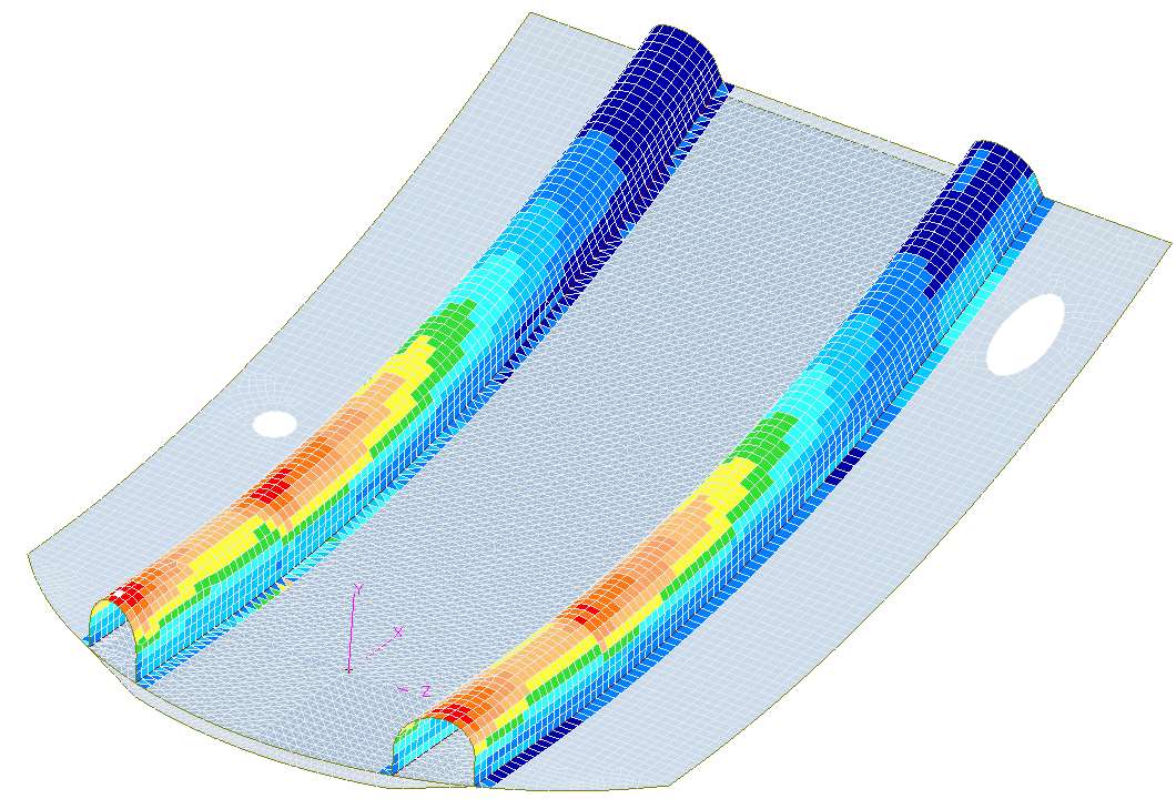
NeiNastran recently aided designers of the dome that shields the Southern Astrophysical Research (SOAR) telescope in the Chilean Andes. The $2 million, 66-ft/20.1m diameter, weatherproof structure consists of an internal steel frame covered with continuous glass fiber-reinforced composite panels, an over-the-top nesting shutter system, rotational friction drive and overhead crane. NEiNastran verified the overall structural adequacy of the 70-ton dome under critical load conditions, including wind, snow and ice. Its internal steel frame and external composite panels were modeled together to take advantage of the substantial stiffening the panels provide. Structural deflections, stresses and member loads were studied under static conditions and the load path variations found during dome rotation. NEiNastran was also used to determine interlaminar shear stress, stiffness and laminate failure indices of the panels themselves (see images at right).
MSC.Software’s (Santa Ana, Calif.) best-known FEA product is MSC.Nastran. It’s designed to work with MSC’s Patran pre-/post-processor and is offered in modules that allow the user to add functionality as needed. The basic configuration allows the user to perform linear and buckling analysis. Other modules offer analysis for heat transfer, dynamics and aeroelasticity as well as nonlinear analysis. For more robust and sophisticated analysis capabilities, MSC offers MD Nastran, for multidiscipline simulations.
Ply-By-ply analysis
As expected, one of the most useful design and analysis tools for composites is software that helps the designer model and optimize ply orientation – particularly in hand layup of fabric and wide unidirectional tape where “draping” becomes a key variable. The challenge software producers face in working on the level of individual plies is to help the user create a layering and orientation strategy that provides appropriate strength in appropriate places over complex curves and angles with a minimum of fiber re-orientation or interference.
Laminate Tools from Anaglyph Ltd. (London, U.K.) performs in this ply-by-ply arena, between the pre-processor and the FEA solver. The program enables the user to define an entire composite structure, ply by ply. It works with pre-processor output to help designers model and manage material usage, ply shape and coverage, fabric straining, layer thickness, fiber orientation, stacking sequence, offsets, thickness distribution and fabric properties. Once a layup schedule is built with Laminate Tools, it can be exported for FEA in either ANSYS or Nastran format. FEA results then can be post-processed in Laminate Tools to view the analysis. Ply information can be exported to automated nesting, cutting and laser ply projection equipment. The software comes with five modules: View, for simple viewing of ply orientation and data; Design, used to create layup information; Analysis, which generates laminate property data for FEA; Check, to display FEA results, and Manufacture, which exports the final ply information.
Two well-known names in FEA, ANSYS Inc. and VISTAGY Inc. (Waltham, Mass.), have collaborated in ply modeling systems. Data from VISTAGY’s FiberSIM fiber draping modeling software can be exported in an .xml format that is readable by ANSYS. The FiberSIM .xml file data contains the order of ply layers and their orientation. ANSYS then allows the user to supplement that data by adding material and thickness information to each layer.
According to VISTAGY, the latest version of FiberSIM, released in November 2006, features enhancements that streamline the design process. VISTAGY’s Guillermin says that one of the most used features is warpage analysis. This module accommodates “spring back” in a part when it is removed from a tool. Thermal deformation can impact the final shape of a composite part by causing it to “spring” when it is removed from the tool. The feature enables engineers to map the ply boundaries of a laminate skin onto the “sprung” skin tool surface, providing full “associativity” between the engineering part and the sprung part. As a result, says the company, all changes made in the design dataset automatically propagate to the manufacturing dataset. Data produced by FiberSIM allows users to design tools with anticipated warpage built in, letting the part cure to the correct specifications. Additional upgrades include 2-D enhancements that provide users with more options for transferring composite data from 3-D to 2-D.
ESAComp, a solid laminate and sandwich panel analysis tool from Componeering Inc. (Helsinki, Finland), has a built-in FE solver for relatively simple analysis (e.g., for beams, plates and joints) and interfaces with widely used FEA software – ABAQUS, ANSYS and Nastran – for more sophisticated analysis. ESAComp also provides post-processing tools. This month, Componeering will release ESAComp 4.0. It features a new GUI for accessing a database of composite materials, laminate layups, structural elements and related load data. New analysis features include thermal conductivity of laminates and enhancements in plate, beam and probabilistic analyses.
In January, ESI announced its draping modeler, PAM-QUIKFORM, within CATIA’s composite design module, allowing fiber simulations that are directly build on the laminate definition in CATIA. PAM-QUIKFORM, predicts the deformation (intra-ply sliding, spreading) of reinforcement fibers during part manufacturing and is designed to alert the user if the selected material can be used to form a draped part without potential problems, such as wrinkling. Data generated by the software are exportable to digital manufacturing machines or nesting and cutting programs.
More to come
As the foregoing indicates, development of composites-specific software modules is ongoing, as composite parts manufacturers outside the aerospace arena adopt FEA into their design practice. As the number of FEA-aware designers in nonaerospace markets grows, FEA vendors see a future in which use of analysis software will significantly expand.


Related Content

Pro-Set named official materials supplier for New York Yacht Club American Magic
Competitive sailing team prepares for the 37th America’s Cup beginning in August 2024 with adhesives, resins and laminate testing services for its AC75 monohull construction.
Read More
Ross coaxial mixer enhances complex material processing
Ross Mixers introduces a custom coaxial mixer designed for blending, dispersing and homogenizing across industries like adhesives, coatings and composites.
Read More
Composite resins price change report
CW’s running summary of resin price change announcements from major material suppliers that serve the composites manufacturing industry.
Read More
Performance resins, putties and structural adhesives
CAMX 2025: Scott Bader illustrates its local and global materials supply availability backed by technical support, as well as a novel composite panels development with Armacell.
Read MoreRead Next

The ABCs of FEA
Computerized and adapted for composites, finite element analysis reduces R&D expense and shortens time to market.
Read More
Scaling up, optimizing the flax fiber composite camper
Greenlander’s Sherpa RV cab, which is largely constructed from flax fiber/bio-epoxy sandwich panels, nears commercial production readiness and next-generation scale-up.
Read More
Ultrasonic welding for in-space manufacturing of CFRTP
Agile Ultrasonics and NASA trial robotic-compatible carbon fiber-reinforced thermoplastic ultrasonic welding technology for space structures.
Read More