
One-shot compression molding enables main rotor blades that achieve 20,000 hours between overhauls
Hill Helicopters engineered composite main rotor blades using a novel single-cure manufacturing process for stiffness and mass distribution optimization.

Share
Read Next


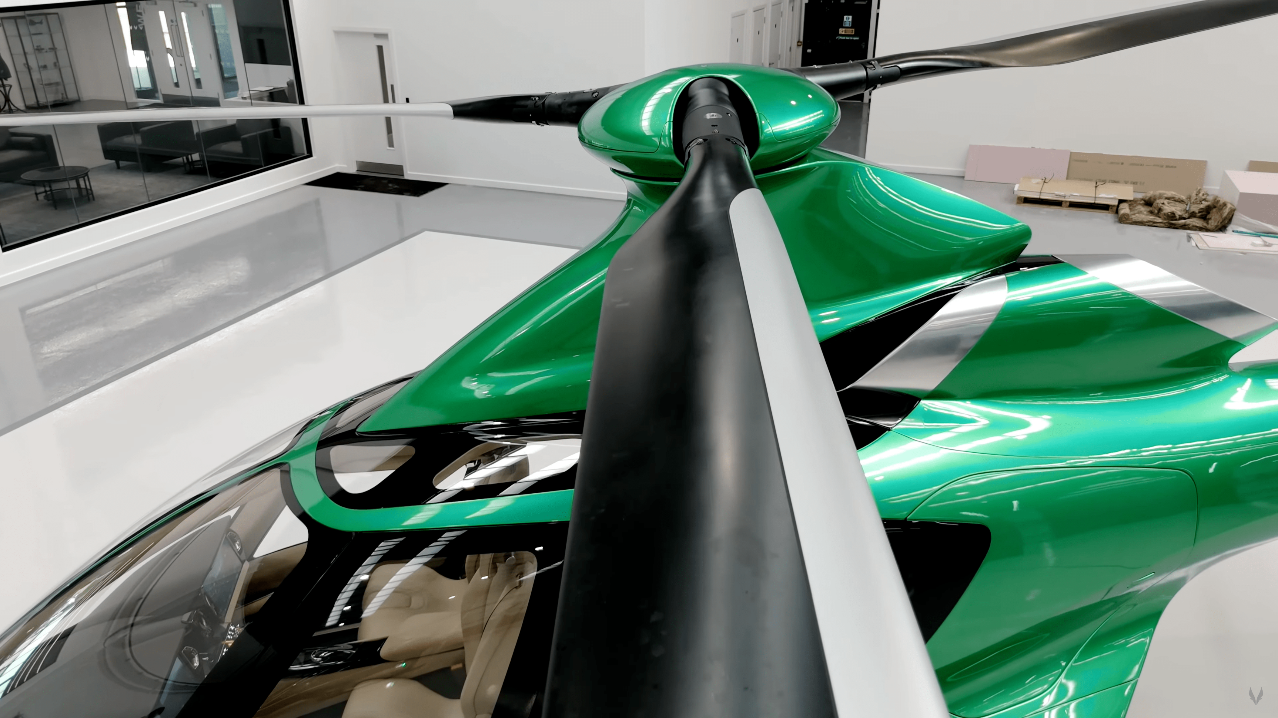
Hill helicopter’s main rotor blade is a complex amalgamation of CFRP, GFRP, unidirectional and biaxial materials that is cured in a single process. Source (All Images) | Hill Helicopters
Helicopter main rotor blades occupy an unusual position in the composite materials landscape. Unlike a wind turbine blade that rotates in relatively clean air, or an aircraft wing that experiences steady-state loading, a helicopter rotor blade operates in a persistently hostile aerodynamic environment. Each blade generates a turbulent wake from the high rate of air pressure change caused by the rotor’s movement through the air. The wake is a churning column of a disturbed flow field of air-containing vortices, pressure fluctuations and velocity gradients, and it doesn’t dissipate before the next blade arrives. Instead, each blade must push through the turbulent flow field left by its predecessor, encountering nonlinear loads that vary dramatically across the rotor disk area.
This blade-vortex interaction generates force frequencies that, if not compensated for in the structural design, can couple with the blade’s natural structural frequencies, creating resonance conditions that accelerate fatigue accumulation. Composite structures, with their directional stiffness properties, require sophisticated engineering to achieve this safe, dynamic behavior.


Read about Hill Helicopter’s fully composite structure HX50 rotorcraft.
This design challenge is further compounded by manufacturing complexity. Composite rotor blades are traditionally manufactured in multistep assembly processes: separately manufactured spars are bonded to skins, foam cores are adhesively attached and erosion shields are mechanically fastened as a final step. Each bonding interface introduces potential variability in stiffness distribution and mass properties — the very parameters that determine dynamic response characteristics. For a structure where positioning natural frequencies within a narrow safe band is critical to achieving acceptable service life, manufacturing-induced variability creates significant engineering margins that ultimately limit performance potential, whether that be service life or operational.
For Hill Helicopters (Stafford, U.K.), and the development of its HX50 helicopter, the use of composites for the main rotor was vital to reach the desired performance of the aircraft which targeted a 140-knot maximum speed, a 20,000-hour time between overhaul (TBO), a manufacturing rate of 12 rotors a day and what the company describes as a class-leading smooth ride. However, the potential variability posed by the multistep assembly processes of a composite rotor blade meant Hill took a different path for the HX50 — developing a one-shot compression molding process that creates the entire blade structure in a single cure cycle.
Think of it like baking a layer cake versus making a soufflé. The traditional approach builds complexity through assembly — mix, bake, stack and frost layers, then repeat. The one-shot method is more like a soufflé: everything goes in at once, and if you get the recipe and timing right, you pull out something that could never be assembled after the fact. This latter manufacturing technique enables more tailored adjusting of the blade’s stiffness and mass distribution through layup sequencing and controlled laminate orientation throughout the structure. However, the biggest gains from doing it this way are manufacturing consistency, repeatability and rate.
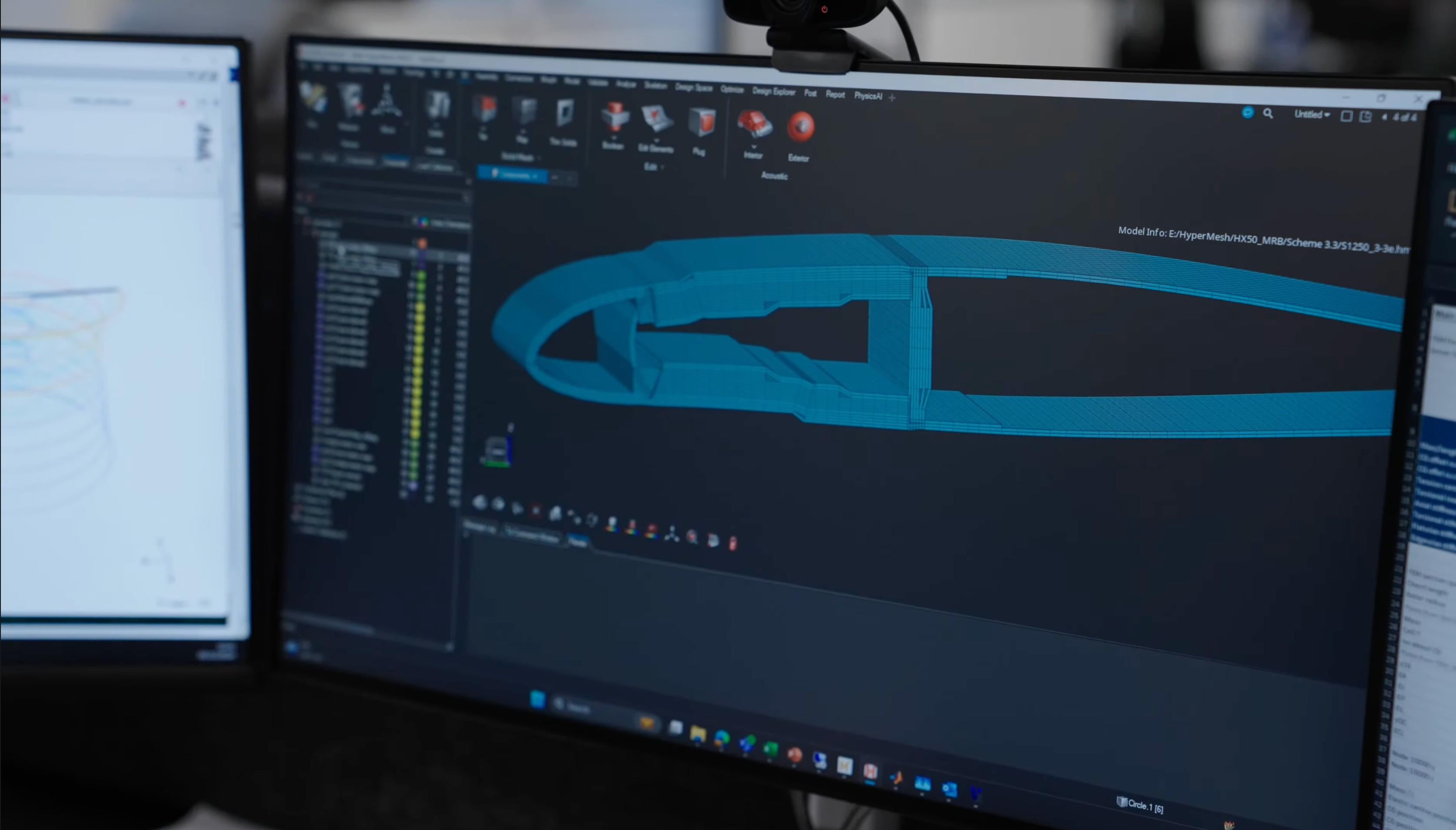
CAD design of the cross-section of the blade.
“When you layer and cure everything simultaneously, you maintain tighter control over fiber placement and eliminate bonding interfaces that can introduce variability,” explains Dean Ridgway, chief composites engineer at Hill Helicopters. “This makes it easier to achieve the precise mass distribution needed for ideal dynamics. The result is a blade with a 20,000-hour TBO that is consistently produced, allowing us to make 12 of them each day.”
Rotor blade design
During the design phase, Hill’s engineering team developed sophisticated rotor wake characterization codes, computational fluid dynamics methodologies and advanced structural dynamic simulations. These tools worked together to define the blade’s aerodynamic profile, stiffness and mass distribution while assessing how the blade would interact with the rotor wake environment. “Rotor wake behavior is a complex, 3D flow field with localized spikes and nonlinear characteristics that are notoriously difficult to predict,” says Ridgway. “You can’t simply calculate it from first principles; you need sophisticated numerical methods validated against experimental data.”
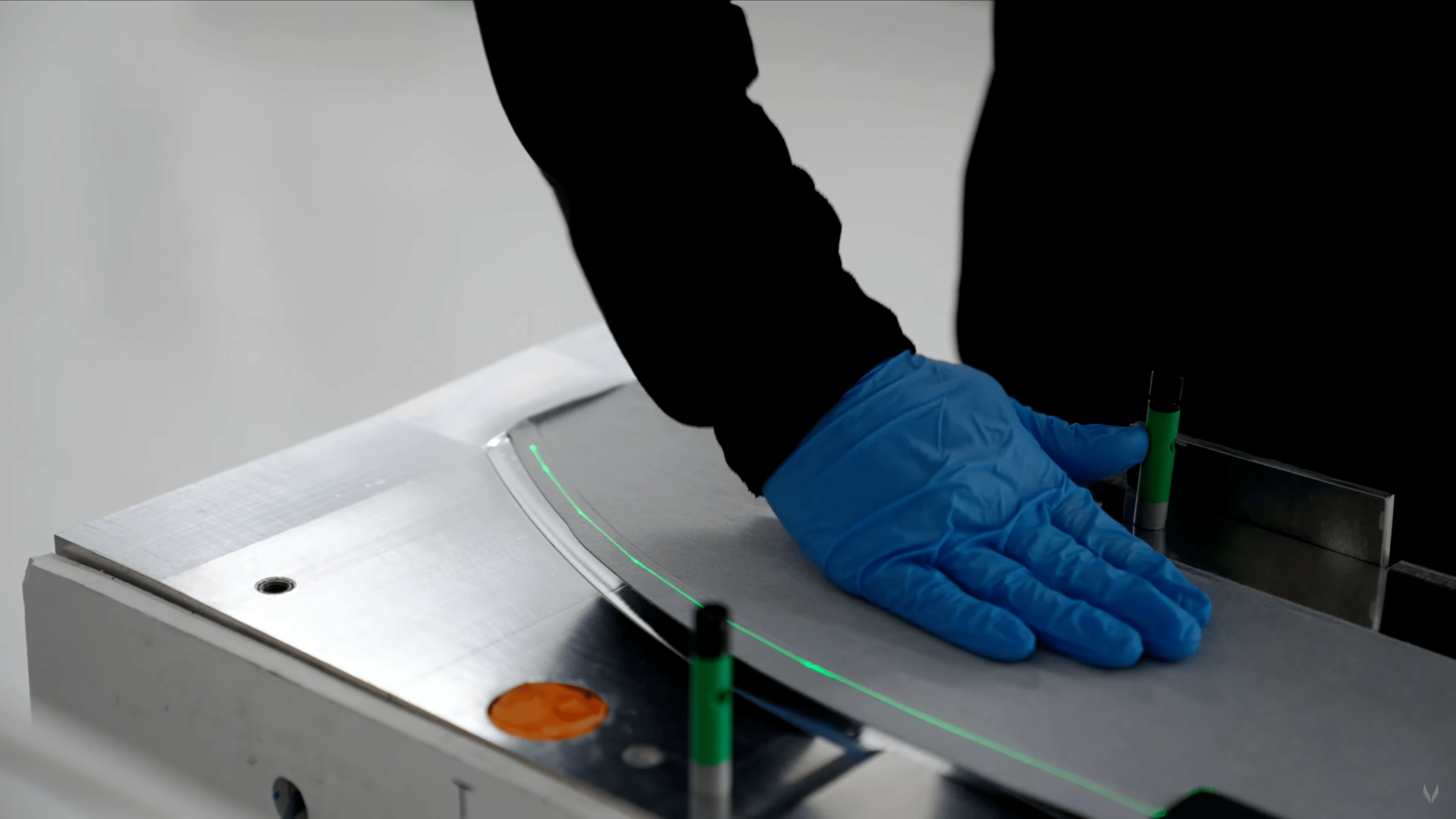
First layer of CFRP ply placed in the mold guided by an overhead laser positioning system.
The blade’s aerodynamic profile includes parabolic tips for low tip speeds, and a continuous rate laminar flow aerofoil profile extending along the blade span. This means the wing profile is tailored for the nominal airspeed over the rotor during operation to produce consistent lift across the length. These features enable the aircraft to achieve its targeted 140-knot cruise speed and lift capacity exceeding 2,000 kilograms from a 500-horsepower engine. The cross-section features a hollow spar with a foam-filled trailing edge. The hollow spar provides the torsional and bending stiffness needed for control response, while the foam-filled trailing edge contributes to the precise mass distribution required for the high-inertia rotor system that gives the aircraft its handling qualities.
Each blade contains more than 100 individual plies of carbon fiber- and glass fiber-reinforced polymer (CFRP, GFRP) in biaxial woven and unidirectional prepreg forms. The material selection enables tailoring of fiber orientation during layup, creating directional stiffness that can be tuned to achieve specific dynamic characteristics, and weight tailoring throughout the rotor length and breadth. The tracking and balancing method employs trim wedges and both span-wise and chord-wise balance weights, providing multiple adjustment options to achieve optimal dynamic balance for the complete rotor system.
The layup process starts with placement of outer skins into the tool halves, establishing the aerodynamic surfaces. Use of laser projectors ensures operators can accurately position each ply while maintaining complete traceability through comprehensive build logs for every layer of every blade produced. This digital integration is essential for aerospace qualification and for identifying any process drift during production. After the outer skin layers, the spar — the primary load-bearing structure — is wrapped around a mandrel and positioned within the tool. The trailing edge core is added, and the upper tool half is clamped into place before curing.
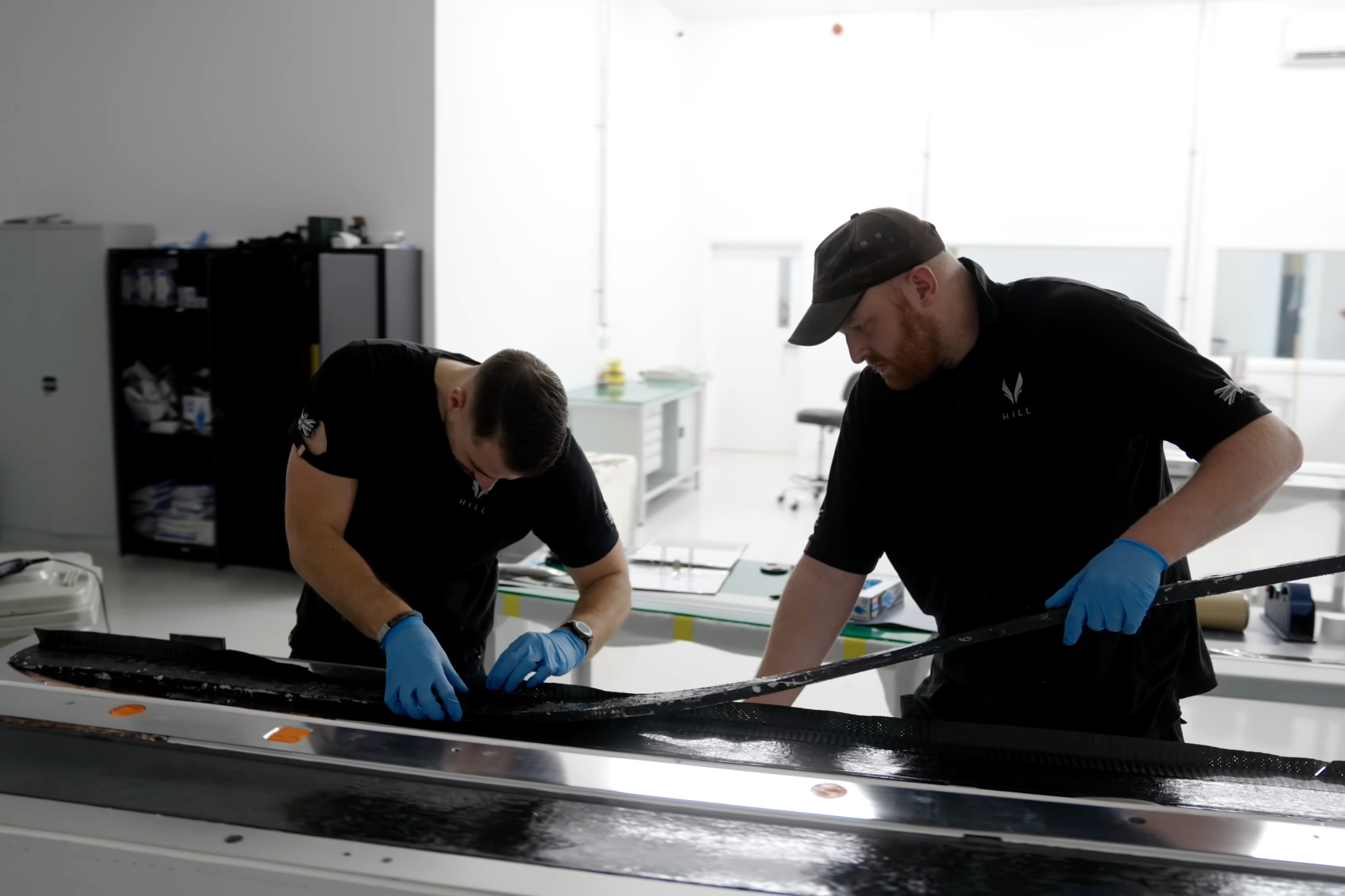
Main spar prepreg plies being wrapped around a mandrel.
“There are no secondary bonding operations, no adhesive layers that might introduce thickness variation, no opportunities for misalignment between separately manufactured components,” remarks Ridgway. “The blade that comes out of the tool is the blade — geometry, fiber orientation, mass distribution, all locked in.” The tooling was designed with scalability in mind. Hill will produce additional mold tools to meet demand. At full production, a total of 12 rotors for four HX50s will be manufactured each day.
Building the molds
The molds for this one-shot process are machined from solid aluminum, fabricated in-house in segments before assembly into upper and lower halves mounted on rigid handling frames. “During machining, these tool halves undergo a rigorous process where they are pre-finished, finished and polished on a gantry mill as a single unit to ensure an impeccable surface,” explains Ridgway. “This method provides dimensional consistency across the production run, a critical factor for achieving the tight geometric and balance tolerances necessary.”
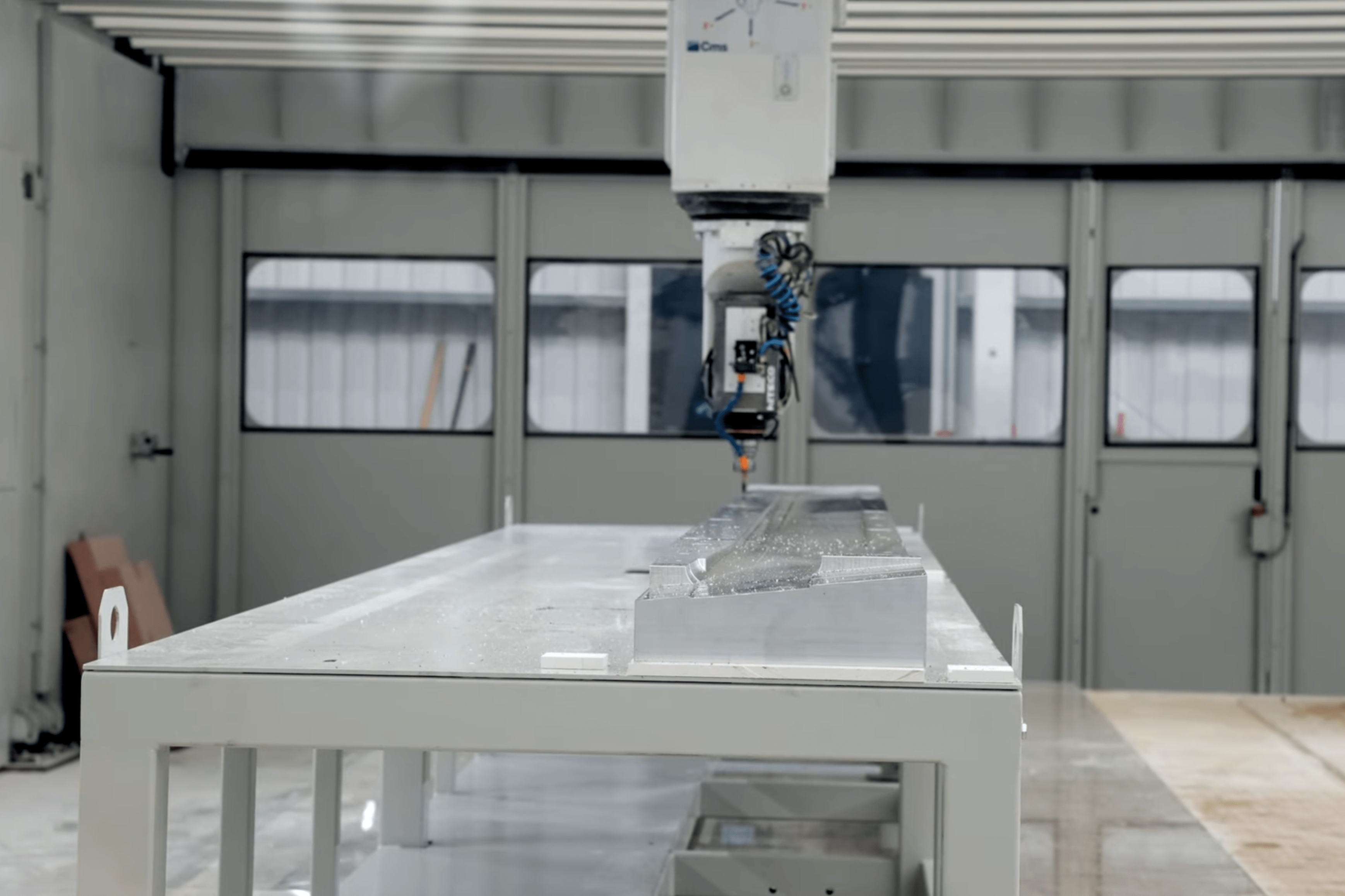
The rotor blade molds are machined from solid aluminum, fabricated in-house in segments before assembly into upper and lower halves mounted on rigid handling frames.
Each tooling half incorporates 15 electric cartridge heaters controlled by a programmable logic controller with integrated thermocouples. These manage the cure profile including temperature ramp rates, hold times and cooling rates. During cure, cycle temperature slowly rises to around 120°C. To reduce residual stresses from thermal expansion differentials, the tooling features a spring-loaded relief mechanism integrated at the root end of the tool. Insulation is used to minimize energy consumption during production cycles while ensuring uniform thermal distribution across the mold surface.
First production blade and validation methodology
The culmination of this development program came in late October 2025 with the successful extraction of the first production blade from the manufacturing tooling. The blade emerged with a gray appearance from the primer film integrated into the mold, ready for further sanding and painting. Initial qualitative assessments suggested the blade’s stiffness and configuration align with expectations, though detailed geometric scanning and computed tomography examination were still to be carried out at the time of writing.
The validation protocol includes both destructive and nondestructive examination methods to establish process consistency and control limits. Comprehensive cut-up analyses of the first production blade will be conducted alongside detailed inspections and measurements. This examination will validate the manufacturing process, and any anomalies identified during the cut-up analysis will inform the focus areas for future ultrasonic inspections or computed tomography scans of subsequent production units. This iterative approach ensures that quality control methods are finely tuned to detect relevant defects while minimizing false positives that could unnecessarily slow down production.
Mechanical qualification testing involves various assessments, including static, dynamic, fatigue and impact tests. These evaluations begin with the end fixture securely anchored to assess the mechanical performance of the blade across its different sections. The testing simulates the complex loading conditions experienced during flight, specifically focusing on the highly dynamic and nonlinear loads generated by interactions with the turbulent rotor wake field.
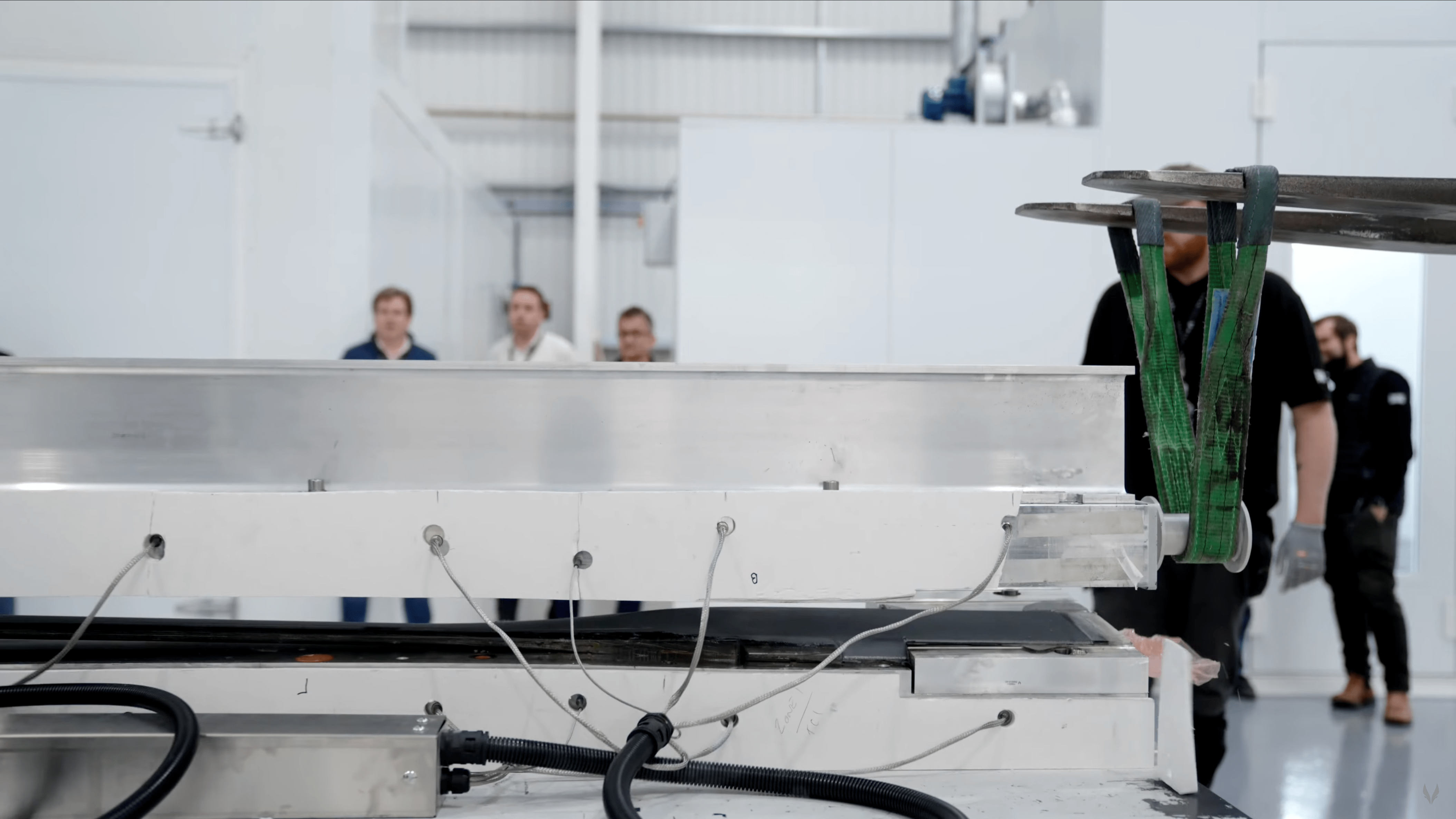
The first HX50 main rotor blade being released from the tooling.
“The development of these advanced composite main rotor blades marks a significant achievement for the company, reflecting years of innovation in design and manufacturing processes,” says Jason Hill, CEO of Hill Helicopters. “By successfully establishing a scalable and repeatable manufacturing process for these cutting-edge composite parts, we are now poised to produce a next-generation helicopter specifically designed for the general aviation market, all while maintaining a competitive price.”
The HX50 rotor blade program serves as a case study illustrating how innovations in manufacturing processes can enable the production of complex, scalable composite parts that would be difficult to achieve with traditional methods. By tailoring the use of GFRP and CFRP, along with hollow and cored structures, and employing a one-shot curing process, the program allows for precise control over the stiffness and mass distribution of the rotor blades, ensuring that the natural frequencies of the blades are positioned outside the rotor wake excitation spectrum, thereby enhancing performance and durability. As a result, this innovative technique is crucial to achieving the targeted 20,000-hour TBO, thanks to the strategic application of engineering intelligence across both design and manufacturing processes.


Related Content

Prepreg compression molding supports higher-rate propeller manufacturing
To meet increasing UAV market demands, Mejzlik Propellers has added a higher-rate compression molding line to its custom CFRP propeller capabilities.
Read More
Plant tour: Collins Aerospace, Riverside, Calif., U.S. and Almere, Netherlands
Composite Tier 1’s long history, acquisition of stamped parts pioneer Dutch Thermoplastic Components, advances roadmap for growth in thermoplastic composite parts.
Read More
Cutting 100 pounds, certification time for the X-59 nose cone
Swift Engineering used HyperX software to remove 100 pounds from 38-foot graphite/epoxy cored nose cone for X-59 supersonic aircraft.
Read More
Ceramic matrix composites: Faster, cheaper, higher temperature
New players proliferate, increasing CMC materials and manufacturing capacity, novel processes and automation to meet demand for higher part volumes and performance.
Read MoreRead Next

Higher performance, lower cost helicopter rotor blades developed with OOA, FAA-qualified composites
Erickson Inc. and partner Toray Advanced Composites replaced legacy aluminum S-64 main rotor blades with out-of-autoclave, multi-material composite alternatives.
Read More
Next-gen fan blades: Hybrid twin RTM, printed sensors, laser shock disassembly
MORPHO project demonstrates blade with 20% faster RTM cure cycle, uses AI-based monitoring for improved maintenance/life cycle management and proves laser shock disassembly for recycling.
Read More
Industrial ultrasonic NDT adaptation permits accessible composite bicycle inspection
Cycle Inspect's ASNT-aligned certification program employs affordable twin-crystal ultrasonic testing equipment and standardized inspection methods to detect damage in composite bicycle components.
Read More


