
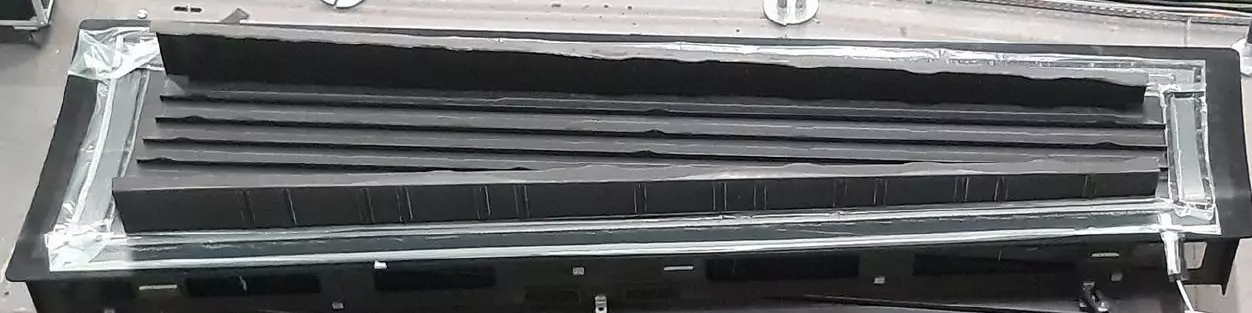


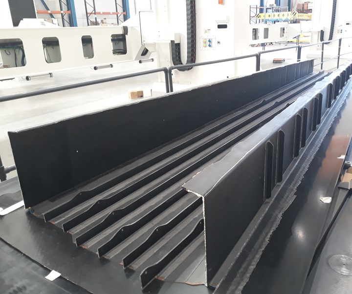
In the Clean Sky 2 IIAMS project, MTorres produced a 4-meter-long outer torque box without fasteners using vacuum bag-only resin infusion for both left and right wings of a C-295 turboprop demonstrator. Photo Credit, all images: IIAMS project, Airbus Defence and Space, MTorres.
As the aerospace industry anticipates its recovery from the COVID-19 pandemic, the previous push for high-rate production has pivoted to an urgent drive to reduce environmental threats to the planet and to people. This effort includes limits on greenhouse gas (GHG) emissions, energy and water usage and creating waste that cannot be recycled. Though these initiatives were ongoing pre-COVID, their emphasis is now heightened, as is the need for much lower cost to produce composite structures. The Clean Sky 2 pan-European aviation program has funded research and development in all of these areas and has significantly advanced a variety of fiber-reinforced composite technologies.
Included in Clean Sky 2’s seventh call for proposals (CFP07, October 2017) is the Airbus Defence and Space (Airbus DS, Cadiz, Spain) request for an innovative and flexible pilot plant to produce a highly-integrated wing box flying demonstrator using automated fiber placement (AFP) and liquid resin infusion.


There have been other resin-infused and/or out-of-autoclave (OOA) wing box demonstrators, including an OOA “blended” wing box unveiled by GKN Aerospace (Redditch, U.K.) in 2013; the Airbus A220 wing produced by Spirit AeroSystems Belfast in Northern Ireland using resin transfer infusion in an autoclave; and the OOA wing produced by AeroComposit (Moscow, Russia) for the MS-21 jetliner. However, all of those have assembled discrete composite stringer-stiffened skins and spars with mechanical fasteners (see “The path to OOA wings with minimal fasteners”).
The wing box requested by Airbus DS in Clean Sky 2 was to take a step forward by integrating the stiffened lower skin with stiffened forward and rear spars, enabling a more complete module without fasteners to be forwarded for assembly with the remaining wing components.
This wing box also would use narrow (0.25- or 0.5-inch-wide) dry carbon fiber tapes and high-temperature (180°C Tg) curing resins, but with energy-saving, low-cost heating systems and sensor-based digital control and simulation to predict and manage processing, shorten trial-and-error loops during development and enable fast training of manufacturing personnel. This digitization would evolve to include an augmented reality mobile application (app) that also provides user and maintenance manuals, process sequence definition, paperless process and parts tracking and projection of CATIA models onto the part to aid in precise placement of stiffener preforms, tooling inserts and carbon fiber-reinforced polymer (CFRP) caul plates.
Perhaps most demanding, this project required that all tooling and manufacturing equipment be portable and flexible, easy to deploy at any manufacturing site, and adaptable for other part designs and upgrades as more advanced tooling, heating and composites 4.0 process control technologies become available.
As explained by the topic manager Luis Rubio, head of composite development engineering – technology and process at Airbus DS, “The final purpose of the project is to demonstrate that an alternative technology (to prepreg and autoclave) with lower costs, reduced lead times and environmental footprint can achieve similar design tolerances and quality levels.”
MTorres (Torres de Elorz, Spain) responded, applying without partners. “We had all of the capabilities in-house: AFP, infusion, dry tape materials and automation,” explains Sebastian Diaz, senior manager of composite applied technologies at MTorres. The company was awarded the Innovative Infusion Airframe Manufacturing System (IIAMS) project, funded via the European Union's Horizon 2020 program under grant agreement No 820845, and began work in October 2018.
Outer wing box demonstrator
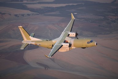
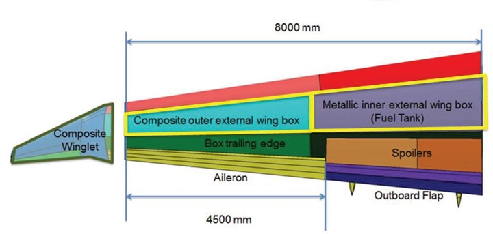
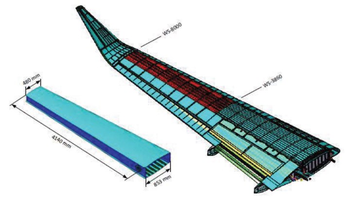
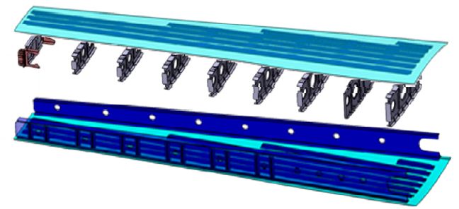
Fig. 1. Outer wing box demonstrator
For the IIAMS project, MTorres produced the outer wing box for right- and left-hand wings based on the C-295 twin-turboprop military transport manufactured by Airbus Defence and Space in San Pablo, Spain. Photo Credit: Airbus (top), Airbus Defence and Space and Clean Sky 2, Fig. 1 on p. 222, CS-GB-2017-10-19 Annex III of WP 2018-9 - CFP07.
The demonstrator Airbus DS chose was an outer wing box based on its C-295 twin turboprop military transport (Fig. 1), produced in San Pablo, Seville, Spain. This 4.14-meter-long composite outboard torque box mates to an inboard metal torsion box. The composite wing box also attaches to a winglet, leading edge and trailing edge.
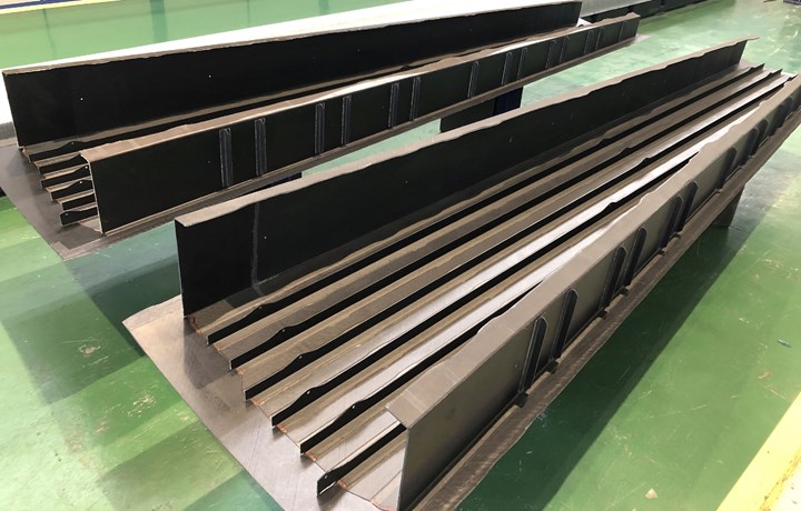
“We were to manufacture two 4-meter-long demonstrators, the right- and left-hand wings, which will be installed for in-flight trials,” says Diaz. “Manufacturing was to be a one-shot process, no secondary bonding. We made only the “U,” comprising the lower skin with six integrated stringers and the spars on each side. The skin, stringers and spars all vary in thickness. The J-shape of the spars and integration of their stiffeners was quite challenging to manufacture. We also faced the challenge of how to maintain tight tolerances and accurate geometry with this manufacturing process. This accuracy is critical, especially at the root for assembly to the inner wing box and then also at the winglet.”
Design of the innovative, industrial manufacturing was developed at MTorres, while Airbus DS provided the part design specifications. “We worked easily together to design the best manufacturing process, verifying that this design could be produced by our process and vice versa,” says Diaz.
Automated center for thermo infusion (ACTI)
Per Airbus DS specification, all tooling and manufacturing equipment used to produce the wing box must be portable, able to be transported to other facilities with standard vehicles and set up quickly without special measures. This led to the development of the automated center for thermo infusion (ACTI), which performs hot drape forming of the stringers and spars; infusion of the stringers, spars and skin; and cure cycles. Hot drape forming (HDF) — developed as heated debulking in aerostructures and as heated preforming outside of aerospace — removes voids in layups and converts 2D blanks for the stringers and spars into shaped preforms (see “Hot drape forming”).
The ACTI has a useful inner area of roughly 5.5 x 2.2 meters and looks similar to a traditional HDF system, with steel frame and an upper half that is electronically raised and lowered, complete with locking and other safety devices. The cure tool and multiple hot drape forming tools are positioned inside the ACTI. “No pressure is applied, only vacuum,” notes Diaz. “ACTI uses heated air with air flow that has been defined to provide fast heat transfer both in the hot drape forming and infusion processes.”
He also notes the system is self-leveling. “The stiffness of the ACTI structure (and the curing tool) has been designed to comply with tolerances under operational loads in a simply supported condition on only two support sections,” Diaz explains. “This means that dimensional accuracy is kept when resting on the floor, with no further leveling or other geometrical tuning required. ACTI also features low energy and low manufacturing costs.”
The latter is due, in large part, to the replacement of assembly of multiple cured parts with assembly of multiple preforms, which are then infused and cured into a single integrated structure. “The curing tool is also the assembly tool,” says Diaz. “All elements are dry preforms assembled into the curing tool and then co-infused together in a single-shot process.” No assembly jig is needed, and strict tolerances are achieved via innovative elements in the tooling.
Another key aspect of this approach is to remove destructive and non-destructive tests (NDT), instead relying on process data collected during the various manufacturing steps to verify process quality and flag out-of-spec parameters. Sensors used with the ACTI collect temperature, vacuum, resin flow and state of cure. “Both air temperature and part temperatures are monitored,” says Diaz. “The tooling has integrated thermocouples that track temperature for the molds and the part surfaces.” All data is recorded, analyzed and used to print graphs and help guide manufacturing decisions.
“Both in IIAMS and in future projects, the data help to improve process setup in the early stages,” Diaz explains. Resin flow and state of cure are monitored using Netzsch (Selb, Germany) dielectric sensors, installed directly into the CFRP cure tools. “We needed non-contact sensors for the skin because there is no direct contact between resin and mold,” says Diaz. “The sensors monitor the change of the dielectric field as the resin arrives and then becomes solid during cure. We used this data to shorten the cure cycle.”
Later in the project, the sensors and ACTI were combined with a human machine interface (HMI) developed by MTorres, which allows true process control from a computer, including vacuum and temperature, as well as resin flow via feed valve. The goal, according to Airbus DS, is to advance mass production of integrated composite primary structures by making the process more streamlined and intelligent.
Lightweight tooling and portability
MTorres produced two sets of molds — one for the right wing and one for the left wing. “Parts with identical geometry, like stiffeners, had only one set,” notes Diaz. “Other tools were shared, when possible.”
A single, one-piece curing tool was used to form the 3D shape of the skin, onto which all of the other preforms were located. Measuring roughly 4.5 meters long, the right and left versions of this tool were made using CFRP, says Diaz. “This makes it easier to maintain tolerances because we designed the tooling with the same layup and processing as the parts, so the CTE is very close to that of the final part. These CFRP cure tools are also lightweight, roughly 200 kilograms, and thus movable with a small electric forklift. This would be impossible if we used metal for a 4.5-meter-long tool.”
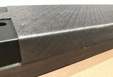
Fig. 2. HDF spar preform
This C-shaped preform for the J-spars began with a flat blank of MTorres novel dry fiber UD tape (up to 10 plies) which was then hot drape formed on a male CFRP tool.
The rest of the tooling — cauls, positioners and HDF tools — were easily managed by hand.HDF of the stringers, spars and spar stiffener preforms used male (IML) tools, also made from CFRP. During use, these were mounted on an aluminum table and set within the ACTI.
AFP using novel dry fiber tape
All of the wing box structural elements — skin, stringers, spars, spar stiffeners — were produced using MTorres AFP technology for dry fiber tapes. “The proposal call said to use fast and cheap materials,” says Diaz. “But commercially available dry fiber tapes, especially from the larger suppliers, were not so easy to purchase and we had the expertise to make our own material (see “Novel dry tape for liquid molded composites”). So, we used our 0.5-inch-wide, 300 grams per square meter (gsm) dry carbon fiber tape made from Mitsubishi Rayon (Tokyo, Japan) 50K high-strength (HS) fiber. Our tape was engineered to facilitate and perform well during infusion, but also during layup using our AFP heads. We know all of the parameters for AFP layup, hot drape forming and resin infusion, and if we needed to make any small changes, we could because we had the tape-making line available.”
MTorres also tested its wing box manufacturing process with 200-gsm tape from Hexcel (Les Avenières, France) made from its intermediate modulus (IM) fiber. “Although our process can work well with both types of tapes,” says Diaz, “during the development phase, it was easier and cheaper to lay with our material versus the commercially available material — the width and stiffness was engineered so that its behavior from spools to table was smooth and fast. It was also readily available.”
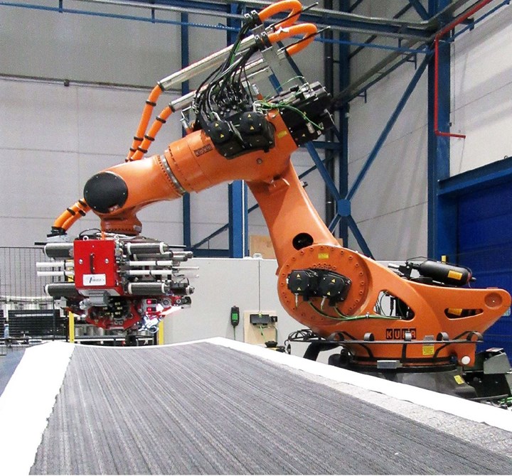
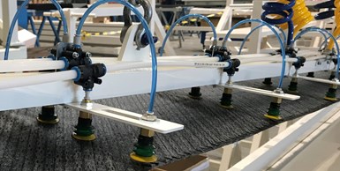
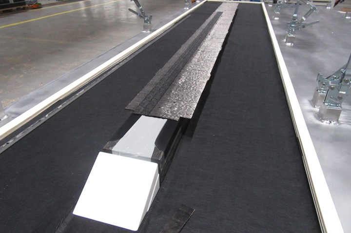
Step 1. AFP was used to lay up wing box skin (shown here) as well as 2D blanks for stringers, spars and spar stiffeners. Photo Credit, all steps: IIAMS project, Airbus Defense and Space, MTorres.
Step 2. Flat tape blanks were transported from the layup table to hot drape forming tools.
He notes that two strategies were followed for AFP: one for the lower skin and another for the stringers, spars and spar stiffeners. The skin (3-6 millimeters thick) was laid to the final 3D shape on top of the curing tool (Step 1), using a semipermeable membrane — patented by Airbus in its Vacuum Assisted Process (VAP) infusion. The stringers, spars and spar stiffeners were laid as flat blanks (2D) onto a vacuum table and then moved onto the HDF tools to achieve their final 3D shape (Step 2).
Heated preforming
Step 3. Stringer blank is placed on top of male HDF tool.
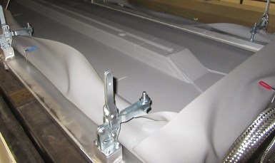
Step 4. Silicone sheet and clamping frame are lowered onto stringer preform for heated debulk/preforming in the ACTI.
“We moved the flat blanks for the stringers, spars and spar stiffeners from the layup table to the hot forming station using a gantry with vacuum grippers,” explains Diaz. “The automated system can move the blanks in a flat state and place them onto the male forming tools [Step 3] without creating wrinkles.” The forming tools were installed on an aluminum forming table, which was placed into the ACTI. A reusable silicone vacuum bag (Mosites Rubber Co., Fort Worth, Texas, U.S.) was placed on top of the blanks, which were then heated in the ACTI to 130°C and shaped using vacuum pressure (Step 4). “Vacuum was smoothly applied following a predefined ramp by means of a control valve when the temperature setpoint was reached,” says Diaz.
He notes that dry tapes are easier to preform/hot drape form, “because the bond between layers is softer than in prepregs. Despite being dry material, it is an HDF/heated debulking in which the resulting preform keeps the shape thanks to the binders included in the tapes.”
For the stringers and spar stiffeners, blanks were formed into two Ls, which were then placed back-to-back on the curing tool to form T-stringers/stiffeners. Each of the six skin stringers is different and requires different shaped blanks to create the preforms. Each of the 24 spar stiffeners is also a different length.
The front and rear J-spars comprise one blank formed into a C, which faces toward the inside of the wing box, and another blank formed into a Z facing toward the outside — the two are placed back to back. The spars also have sinusoidal-shaped feet on the outside of the wing box (arrow in Step 7). “We cut the shape for the spar feet on the flat layup table before we moved the blank to the forming station,” says Diaz. “Nothing could be trimmed or milled afterward in this area. The blanks were placed straight onto the male forming tool with the spar feet at the left side of the tool and the top flange at its right side.”
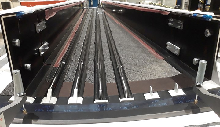
Fig. 3. Precise preform placement. Preforms for J-spars and stringers were positioned using twin metallic cylinders (seen at far left and right), white positioners and a CFRP caul with cutouts for the stringers/positioners. Photo Credit: IIAMS project, Airbus Defense and Space, MTorres.
One-shot infusion
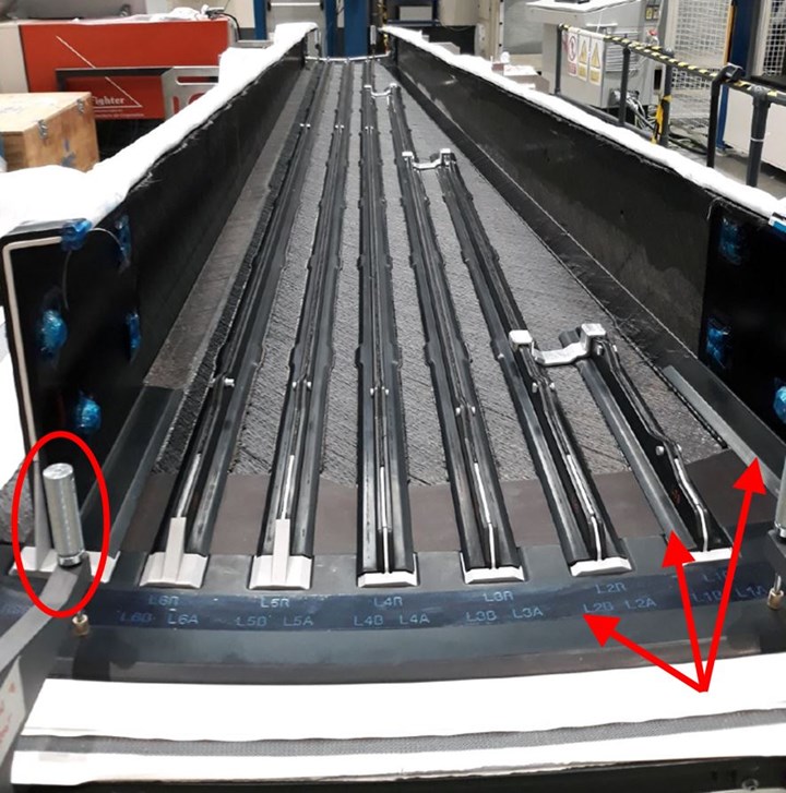
Step 5. Stringer and spar preforms were placed onto the lower skin, aided by cylindrical (circled) and white positioning elements. Black CFRP cauls (arrows) were also used to help position stringers and placed on top of stringers and J-spars.
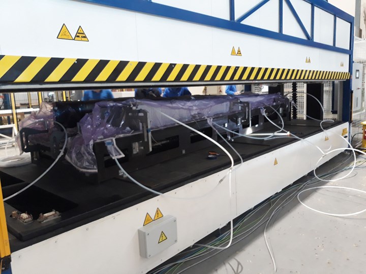
Step 6. Preform assembly is vacuum bagged and prepared for infusion in the ACTI.
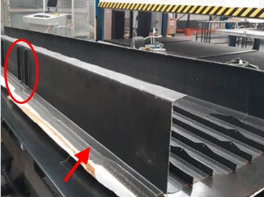
Step 7. Initial demonstrator completed at MTorres shows the J-spar with two rib stiffeners (circled) and its sinusoidal feet (arrow).
The next step was to place the stringer, spar and spar stiffener preforms onto the already laid lower wing skin (Step 5). “We were indexing each preform as we placed it onto the skin and cure tool,” says Diaz. Cylinders that act as location elements can be seen at the end of the spar on the left of Step 5 and at the end of both spars in Fig. 3. These images also show white positioning devices for the stringers and J-spars. There were 13 of these positioners in the final preform assembly, and each one was different.
Caul plates were also a key part of the preform location and placement system. They served the traditional purpose of maintaining uniform pressure and temperature across regions of complex layups and/or geometry, but would also be key for infusion, as discussed below. A black CFRP caul plate with cutouts for the stringer preforms can be seen at the end of the stringers and spars in Step 5 and Fig. 3.
“The location of the stringer preforms depends on the location of that caul,” Diaz explains. “The digital technology that we developed to monitor and control the manufacturing process included an augmented reality app that projected the CATIA models onto the layup. This was used to help guide placement of the caul plates, positioning elements and then preforms. It also showed the next steps to be performed. The app allows self-support on tablet computers so that all workers have easy access to all information.”
A final set of black CFRP caul plates were then placed on top of the L preforms for the T-stringers and also along the inside and outside of each J-spar, extending up onto the flange and down onto the foot on the outside of the wing box, as shown in Step 5 and Fig. 3. “Spars also make use of a sort of caul plate on the inner side at the ends, in order to get increased accuracy in the joint areas,” says Diaz. “All of these caul plates were used during the HDF process and remained attached to the preforms through layup.”
The completed dry preform assembly with caul plates was then covered with peel ply and a vacuum bag film. The entire assembly of skin, stringers and spars was then placed into the ACTI and the tooling was heated to 120°C. Hexcel RTM6 epoxy resin was heated to 70°C and degassed before infusion through a single resin feed location. “The ACTI was prepared to feed resin from four locations,” notes Diaz, “but after extensive simulation and tests, we decided it was easier and cheaper to have a single resin inlet.”

Figure 4. Complex infusion: Red areas in the PAM-RTM resin flow simulation show the four corners were the most challenging areas to achieve wetout during infusion. Photo Credit: IIAMS project, Airbus Defense and Space, MTorres.
Even with a single inlet, the infusion process was very complex, comprising three different modes. “We first performed flow simulation, using PAM-RTM software [ESI Group, Paris, France],” says Diaz. “There was such a complex mix of flow fronts and parameters needed for complete wetout. For example, resin flow was faster in the center of the wing box, but it was a challenge to wet out all of the stiffeners.”
VAP, with a semi-permeable membrane, worked well for the lower skin, but this was exchanged for high-temperature flow mesh along the stringers and on the inside of the spars. “The corners were the most challenging areas to wet out,” notes Diaz, “but they were also the most critical for holding tolerances for assembly, as well as along the edges.” This can be seen in the red areas of the flow simulation in Fig. 4. “In these areas, a customized approach was developed to achieve the precise dimensions required,” he explains. We also used vacuum ports along the perimeter and on top of the spars.”
The infusion was relatively quick, as predicted by simulations, followed by a two-hour cure at 180°C, using only hot air, and not heated tooling. After being demolded, each wing box demonstrator was then inspected using ultrasonic testing (UT). This was done as part of the IIAMS project deliverables, to analyze the quality of the demonstrators. Industrial application of this process, however, will reduce traditional NDT in favor of digital sensors and faster inline inspection tools such as vision systems.
According to Diaz, although the infusion cure cycle was similar to that for an autoclave-cured prepreg wing box, the overall cycle time should be lower. “We have eliminated most of the assembly afterward and we also don’t have to shim anything like with prepreg, yet our quality is the same. For example, the bonding between the last layer of the skin and the first layer of a stringer needs no adhesive film in the middle to improve mechanical properties and account for tolerances.” This is obviously more efficient, but he notes that part production rate was not initially the driving factor. “This method is not competing with manufacturing of individual parts but with a completed wing box assembly.”
Complete demonstrators, path to certification
“We had only 18 months to complete this project, which included designing the process and tooling and manufacturing the tooling and demonstrators,” says Diaz. “By month 14, we had the first demonstrator ready for display at JEC in late February 2020 [Step 3], but then JEC was canceled due to the pandemic. Although the project finished in late September 2020, if you subtract the months we could not work due to COVID-19, we actually finished in month 16. We were able to keep this very tight schedule due to our in-house design capability and ability to manufacture the tooling prototypes using our AFP and CNC milling machines.”
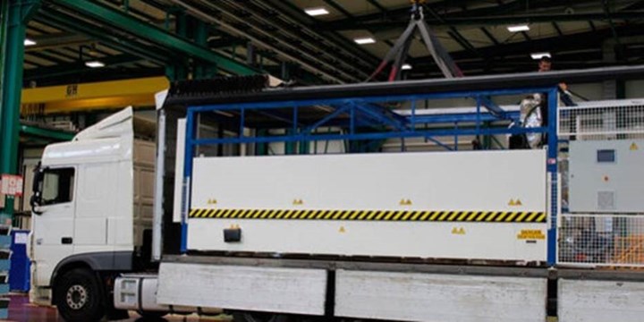
Step 8. ACTI forming/curing equipment and wing box tooling were lifted onto a standard moving truck and relocated to Airbus DS in Cadiz, Spain.
Step 9. The final wing box was manufactured at Airbus Cadiz. IIAMS project left and right wing boxes for flight test are shown here.
A simplified, 1-meter-long demonstrator was made at MTorres to check all of the process parameters. Then, the first full-size demonstrator was produced. Tooling and manufacturing equipment were then relocated to Airbus DS in Cadiz (Step 8), where the final demonstrator was produced. This was also part of the project’s deliverables, proving that the equipment could be easily transported and installed at multiple locations.
As explained in the sidebar, “IIAMS wing box road map to certification,” Airbus DS has played a key role in the Clean Sky program, progressing from co-leader of the Green Regional Aircraft (GRA) integrated technology demonstrator (ITD) in Clean Sky, to co-leader of the AIRFRAME ITD, as well as leader for the flight testbed 2 (FTB#2) in the REGIONAL integrated aircraft demonstrator platform (IADP) within Clean Sky 2. The FTB#2 will include other composites and airframe developments, including in the cockpit and other wing components.
All of the projects to prepare the FTB#2 are, in fact, part of a broader, long-range strategy at Airbus. The goal is to develop a future turboprop airframe that is lighter and more efficient, and production processes that are cheaper and use less energy, manufacturing liquids and ancillary materials, yet also generate less scrap and offer increased recyclability.
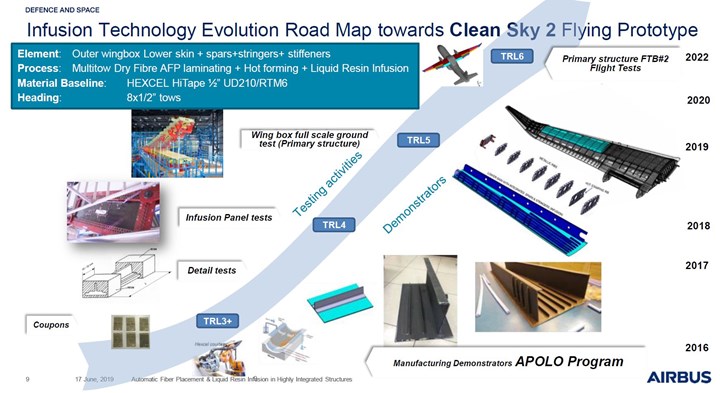
Fig. 4. Liquid resin infusion roadmap - path to certification
The IIAMS wing box demonstrator is the latest step in a multi-year strategy to mature a dry fiber AFP/resin-infused wing box to TRL 6 by 2022 and lay the groundwork for its certification in a future regional turboprop aircraft. Full-scale component structural testing of the IIAMS wing box will complete design qualification requirements for the Clean Sky 2 Flight Test Bed 2 (FTB#2).
Photo Credit: Fig. 1, “Structural Radar Research of Airbus Defense and Space as Clean Sky Partnership” by Manuel Iglesias Vallejo, Rubén Tejerina Hernanz, Antonio Jiménez, et al., Airbus Defence and Space, 8th European Conference for Aeronautics and Space Sciences (EUCASS), July 1-4, 2019.
“Step by step we [Airbus DS] are going through the entire airframe structures test pyramid from coupons to the full-scale structural tests of the outer wing,” explains A.E. Jiménez Gahete in a September 2020 Materiales Compuestos article titled, “Airbus Defence and Space highly integrated wing box section manufactured by dry fiber placement and liquid resin infusion.” Materials characterization testing, a design details test matrix and subcomponent tests for design allowables have all been completed with positive results. MTorres aided in this testing, including manufacturing test coupons and parts, as well as demonstrators to validate the wing box manufacturing process and design details. Only the final outer wing full-scale static and functional tests remain, says Gahete, to obtain the FTB#2 qualification for flight.
“One-shot infusion reduces joints, decreases weight and increases robustness,” says Diaz. “The novel dry tape MTorres has developed produced excellent results, both in the processing — AFP, hot drape forming and infusion — and in the part’s structural properties.” He notes that, historically, there has been doubt that resin-infused composites could match the same structural performance and tolerances as autoclave-cured prepreg.
“To get the same tolerances in a single-shot process with soft [non-metallic] tooling was our greatest challenge,” he concedes. “But we have proven this technology works and that it can produce the large primary structures needed for future aircraft. Our next step is to keep advancing the digital technologies and portability of the production system.”


Related Content

Prepreg compression molding supports higher-rate propeller manufacturing
To meet increasing UAV market demands, Mejzlik Propellers has added a higher-rate compression molding line to its custom CFRP propeller capabilities.
Read More
Modular composites enable larger tanks for wastewater and biogas reactors
Toro Equipment uses biaxial fabrics, carbon fiber and Flex Molding for corrosion-resistant tanks that compete with steel, concrete and speed global installations.
Read MoreRead Next

Ceramic matrix composites: Faster, cheaper, higher temperature
New players proliferate, increasing CMC materials and manufacturing capacity, novel processes and automation to meet demand for higher part volumes and performance.
Read More
Ultrasonic welding for in-space manufacturing of CFRTP
Agile Ultrasonics and NASA trial robotic-compatible carbon fiber-reinforced thermoplastic ultrasonic welding technology for space structures.
Read More
Cutting 100 pounds, certification time for the X-59 nose cone
Swift Engineering used HyperX software to remove 100 pounds from 38-foot graphite/epoxy cored nose cone for X-59 supersonic aircraft.
Read More