


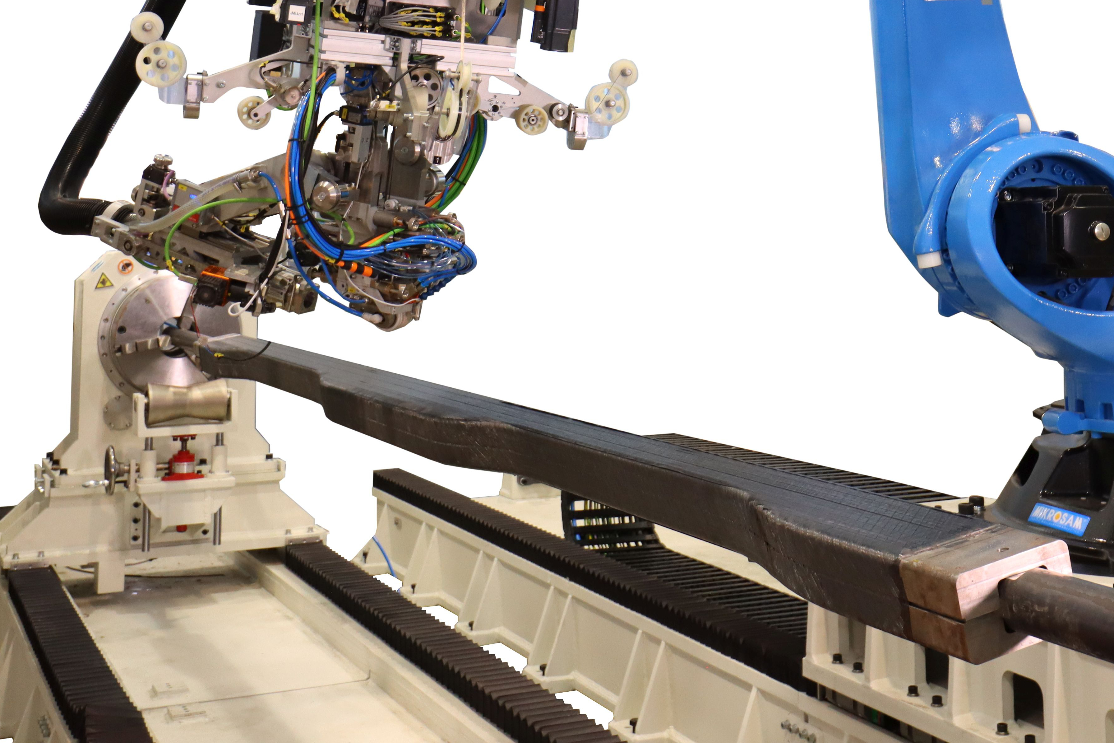
AFP of thermoplastic composite floor beams. Composite floor beams are not new, but using thermoplastic prepreg tape and advanced fiber steering to produce them is, and has been successfully demonstrated by GKN Fokker and Mikrosam during development and manufacture of the 12 TPC beams used in the passenger cabin floor grid for the Multifunctional Fuselage Demonstrator (MFFD) lower half. Photo Credit for all images (including image in line with title): GKN Fokker, Clean Sky 2/Clean Aviation
The Multifunctional Fuselage Demonstrator (MFFD) is paving the way for next-generation airframes made using thermoplastic composites (TPC) instead of primarily thermoset composites — mostly carbon fiber-reinforced epoxy — used for aerostructures today.
Funded by the EU joint research and innovation program, Clean Aviation, the materials and processes being advanced in the MFFD will enable increased aircraft production — for example, 70-100 narrowbody aircraft/month. These technologies will also enable reduced CO2 emissions by using lighter weight composites as well as reduced cost by replacing a majority of fasteners with TPC welding to produce integrated structural modules for final assembly. The project’s final 8 × 4-meter fuselage section — to be completed in early 2024 — will be the largest all-TPC structure ever built.


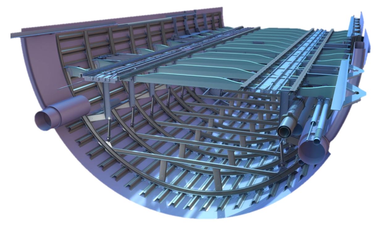
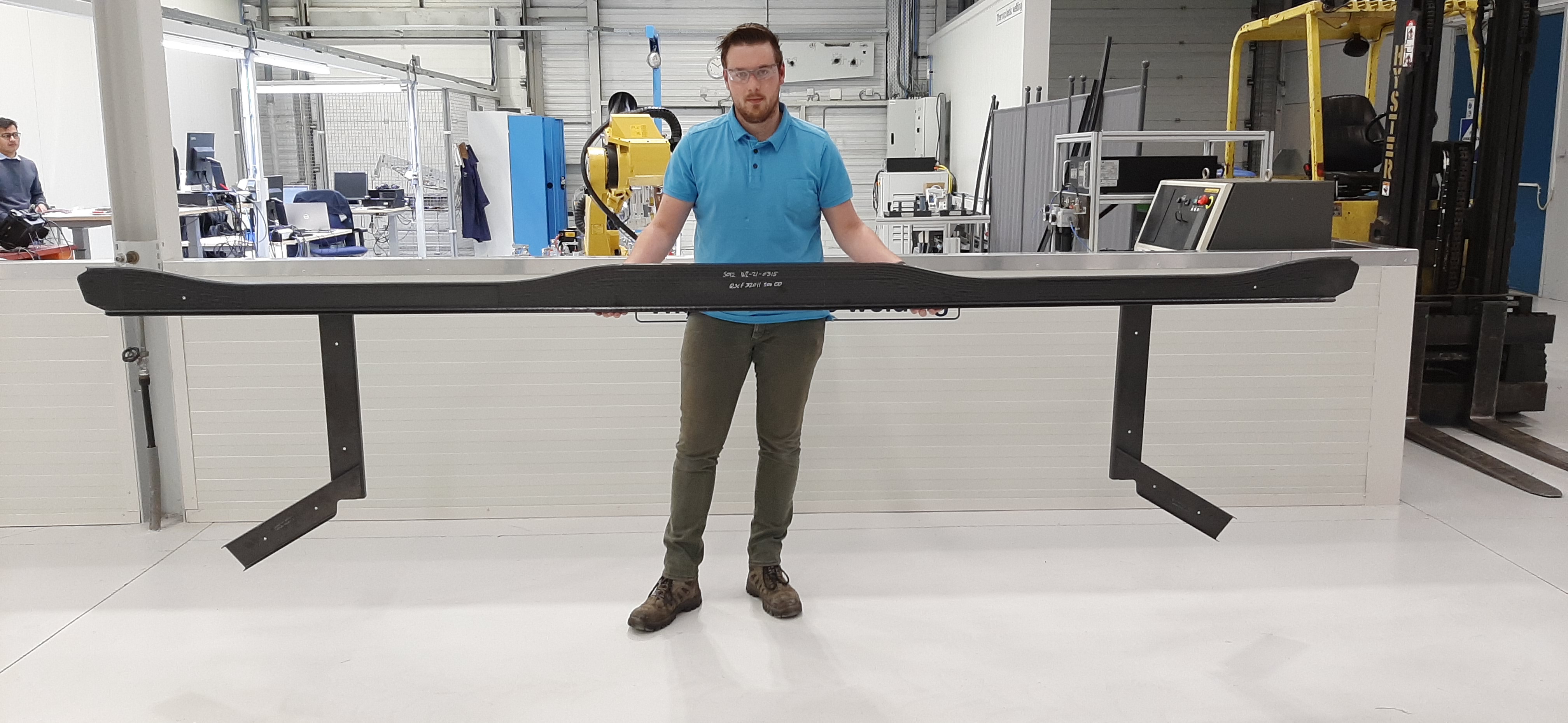
Fig. 1. Full-size beams for passenger floor grid
The MFFD lower half includes a structural grid for the passenger cabin floor across its top, including metal seat rails (top). GKN Fokker produced 12 CF/LM-PAEK floor beams with conduction-welded vertical struts (bottom) which would then be conduction welded to the fuselage frames in the finished module.
GKN Fokker (Hoogeveen, Netherlands) has led production of the MFFD lower half in the STUNNING subproject. Completed in late 2022 and shipped to Fraunhofer IFAM (Stade, Germany), the lower half will be joined to the upper half later this year using an advanced laser in-situ joining process developed with Fraunhofer IWS (Dresden, Germany). The lower half includes a structural grid for the cargo compartment floor and another grid for the passenger cabin floor. The latter comprises 12 TPC floor beams with welded TPC brackets for attaching metal seat rails and welded TPC vertical struts to attach the floor grid to the fuselage frames (Fig. 1). These brackets and struts are joined using conduction welding (see “Thermoplastic composites welding advances for more sustainable airframes”).
This article discusses GKN Fokker’s two-year development of the TPC floor beams in collaboration with equipment supplier Mikrosam (Prilep, Macedonia), including an innovative automated fiber placement (AFP) layup strategy using tow steering, followed by autoclave consolidation. A follow-on development uses a specially designed press and bladder concept to enable consolidation without an autoclave for future production of 6-meter-long spars for TPC rudders. For more details on GKN Fokker’s long history in TPC aerostructures development, see “Fokker Aerostructures: Hoogeveen, The Netherlands.”
AFP layup and tooling
The MFFD floor beams have a C-section shape with varying web height and thickness along their length. “The shape is quite similar to the Boeing 787 floor beams,” says Arnt Offringa, director of the GKN Aerospace (Solihull, U.K.) Global Technology Centre Netherlands (GTC-NL, Hoogeveen). “There’s often a recess in the beams to allow spacing for electrical and other systems. The complexity of the geometry and layup was why we chose AFP, and the process developed was a joint effort between GKN Fokker and Mikrosam.”
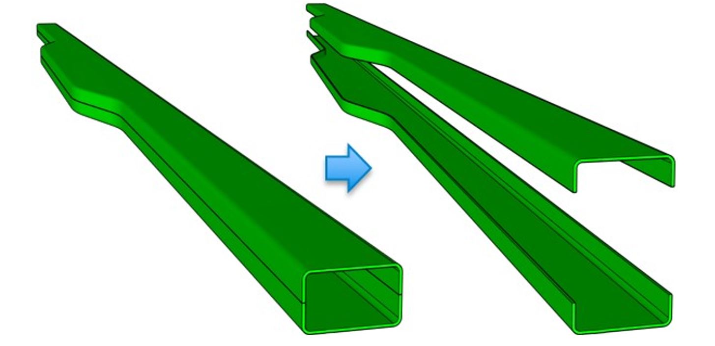
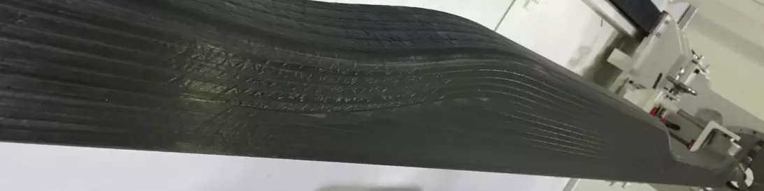
Fig. 2. One mandrel, two preforms. GKN Fokker developed a shaped steel mandrel with a cutting channel in the middle to facilitate cutting the single AFP layup into two MFFD floor beam preforms.
GKN Fokker developed a strategy to lay up two beam preforms simultaneously on a shaped steel mandrel with a cutting channel. The latter aided cutting the layup into two preforms before consolidation (Fig. 2). “This is a very efficient approach, with much less waste than when the preforms are made separately,” says Offringa.
Vele Samak, general manager of Mikrosam, agrees noting, “It also minimized the layup time by optimizing the AFP path. Courses are laid continuously as the mandrel rotates, which minimizes cuts and restarts. This helps to maintain consistent quality and makes the process much simpler. It also maintains good tension on the fiber. This helps to prevent warpage and results in a layup that is almost consolidated, which then helps to reduce cycle time for the subsequent consolidation step.”
“To speed up the development process,” says Offringa, “a first set of beams was produced at Mikrosam’s R&D facility.” Subsequent beams were made with a new 8-axis AFP machine from Mikrosam installed at the GTC-NL. The center also installed Mikrosam equipment for slitting thermoplastic prepreg tapes and a custom consolidation press, discussed later.
“The AFP machine features a modular, multi-material head and high-temperature laser heating system,” says Samak. “GKN Fokker is using it now to develop thermoplastic technologies, but in the future, they can use it also for dry fiber or thermoplastic prepreg tapes which use thermoplastic binders. Our AFP heads are modular so that you can attach the same head to different configurations while being inherently multi-material without requiring modifications. Thus, it offers a lot of flexibility and upgradeability as new technologies develop.”
Offringa notes that development began with materials from Solvay Composite Materials (Alpharetta, Ga., U.S.). However, the STUNNING floor beams were made using Toray Advanced Composites (Nijverdal, Netherlands) Cetex TC1225 tape comprising T700 carbon fiber (CF) and a low-melt polyaryletherketone (LM-PAEK) matrix. This material system was chosen for use throughout the STUNNING demonstrator, with input from Airbus as the MFFD project leader. Although the Mikrosam AFP head can deposit four tapes at once (1-inch-wide course), it was decided to use two tapes during layup to accommodate the geometry and achieve better consolidation at the low-radius edges of the floor beams.
Fiber steering, optimized design and process
“The layup strategy, which uses fiber steering, evolved during the manufacturing development process,” says Offringa. “Before the advent of AFP, we always stuck to 0°, 90° and 45° layups. But with AFP, we need and want to use fiber steering to achieve, for example, double-curved panels without wrinkles or gaps and with the fibers best oriented for the structural loads. However, fiber steering is relatively new in manufacturing. But we will see it more and more with AFP and thus increasing deviation from more traditional, standard layups.”
The floor beam layup started with a radial first ply, slightly deviated from the typical 90° angle, explains Samak, “to achieve continuity of the fibers and good fixation to the mandrel. A lower temperature was used since this ply had nothing below to consolidate with. For better fixation onto the steel mandrel, Kapton [high-temperature polyimide] tape was used.”
Zero-degree layers
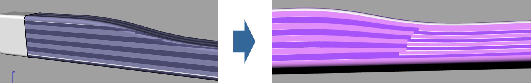
Fig. 3. Fiber steering for improved 0° plies. GKN Fokker worked with Mikrosam to optimize the floor beam AFP layup. In the diagram above, the layup on the left is not optimized, while on the right 0° plies no longer stop in the radius area, but instead further down the slope in a flatter area of the web. This reduced ply starts and stops in a difficult area, as well as gaps and overlaps, and made the AFP process more efficient.
“The 0° direction is along the beam,” explains Offringa. “In the final layup sequence, 0° plies no longer stopped in the radius area, but further down that slope in a flatter area of the web [Fig. 3 diagram]. This diagram shows these two strategies. The beam on the left was made with a non-optimized layup while the layup on the right was really very elegant. It reduced gaps and overlaps and improved the layup process.”
Note, the layups shown in Fig. 3 are being built up on top of a curved mandrel. “In the image on the left,” continues Offringa, “fibers are either continuous over the whole length of the beam or they start and stop at this angled section in the beam, which is not so easy. You are trying to create this radiused section of the beam, and yet you create a corner by stopping each 0° ply. It is also not easy to start and stop at these locations due to the complex shape of the beam. So, Mikrosam’s engineers helped us modify the AFP layup program so that fibers were more steered to have the same performance, but with a more friendly manufacturing route.”
Optimized process parameters and 45° layers
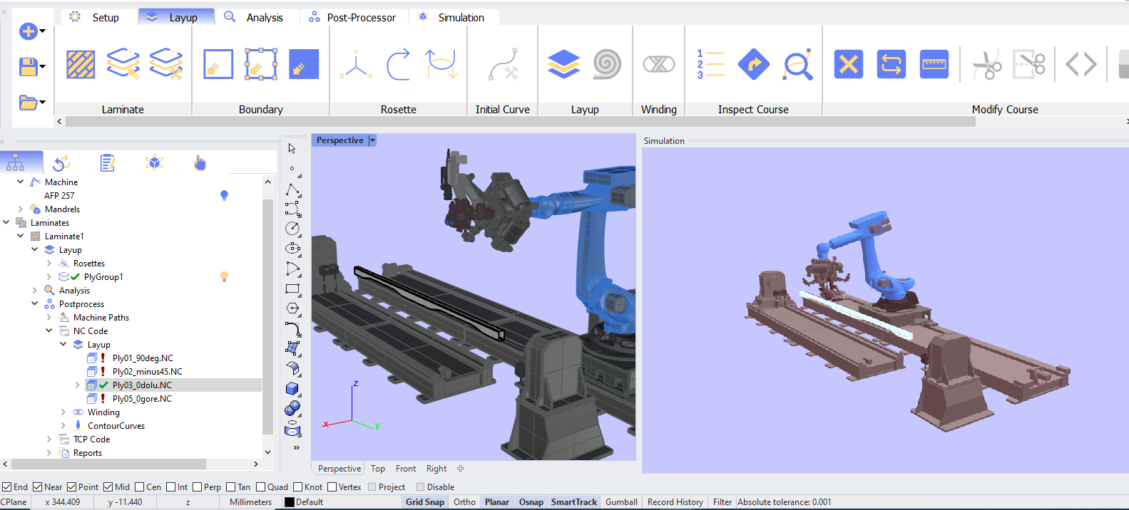
MikroPlace software was used to generate the machine code for the AFP layup process. To start, the designed layers, tow drop zones, gaps/overlaps and possible collision issues were simulated in MikroPlace, and solutions — e.g., a larger angle for the first ply — and different layup rosette strategies were analyzed together with the GKN Fokker team.
MikroAutomate software was then used to simulate the online machine control. A team from Mikrosam, the Institute for Advanced Composites and Robotics (IACR, Prilep, Macedonia) and GKN Fokker optimized the layup design with respect to process parameters. “For example,” explains Samak, “changing the angle of the AFP head to avoid collision will change the laser angle, resulting in a different heating zone. Modifying the layup temperature may be required to address this.”
He continues, “Our AFP machine control software allows you to fine tune how much laser output you have in different sections of the courses and layers. Using a standard control where you just output power in proportion to the speed of the AFP head is not enough, for example, where you have steep curves. You will likely need to reduce some of that laser output in this specific section so that you’re not burning the incoming material.”
Another optimization in the floor beams was in the 45° plies. Samak notes that MikroPlace software enabled specification of each 45° ply separately for each course of tapes. “This means that our software allowed finer modification of the course paths for each of these plies,” he explains. “As you’re programming the AFP head for the 45° plies, you end up with course deviations, especially in that middle bulky area of the beam where you ramp up and then drop down again. So, as you’re doing the 45° layup, you have to manually address the deviations that occur. The MikroPlace software allowed the team to fine tune these layups so that there were no gaps or overlaps.”
MikroPlace software enabled optimization of 0° and 45° plies in the floor beam AFP layup design.
What about in-situ inspection for gaps and overlaps? “We don’t have an inline inspection system on this AFP machine,” says Samak, “but we record the layup with a process camera and thermal camera. With both of these, the operator can monitor if there are any gaps or overlaps during the layup process and also see if they’re going out of desired targets. For example, if the incoming tape is thinner, it will be noticed on the thermal camera at once, since that area will be heated differently. The operator can stop the layup if necessary and address this.”
Autoclave consolidation, floor grid assembly
After each layup was completed, it was slit into twin preforms. All 12 preforms were then autoclave consolidated into the TPC beams to minimize porosity in the finished structures. “We vacuum bagged the preforms using our standard high-temp Kapton film for thermoplastics,” says Offringa, “and used 6 bar of pressure during a 6-hour autoclave cycle. The only finishing required was to cut the flanges to width.”
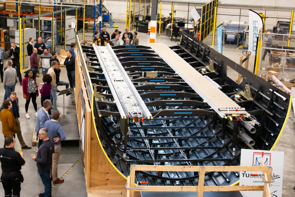
Fig. 4. Completed MFFD lower half. The STUNNING project, led by GKN Fokker, has completed assembly of the MFFD lower half, shown here at SAM|XL. The module has been transported to Fraunhofer IFAM (Stade, Germany) where it will be joined to the upper half using a laser-based welding process developed by Fraunhofer IWS (Dresden, Germany). Photo Credit: SAM|XL
“The beams were then assembled into the MFFD floor grid,” says Offringa. “The beams were welded into the lower fuselage shell which had frames already installed. The connection between the floor beams and the fuselage frames was made with our patented new conduction welding process which uses a heated rod element with an anvil to apply counterpressure.” He notes the same process was used to produce the welded fuselage with frames subassembly that GKN displayed at the JEC 2022 show’s mobility planet. “We use an element that is heated and cooled,” he points out, “and that transfers via conduction by touching the parts being joined. The element is mounted on a robot which basically moves it to each weld position. At SAM|XL, that robot is on a gantry.” SAM|XL is the Smart Advanced Manufacturing XL research center on the campus of TU Delft (Delft, Netherlands), where the MFFD lower half assembly was completed (Fig. 4).
How long did this TPC floor beam development take? “To develop the beams was part of the STUNNING project as a whole,” says Offringa. “We started in early 2021 and it took about nine months. Of course, we had to have the equipment installed and Mikrosam helped us out — before our new AFP machine was operational — by producing the first two experimental beams. We then transferred the tool to the GTC-NL and continued the development. We made the 12 beams for the MFFD in about six months.”
OOA consolidation
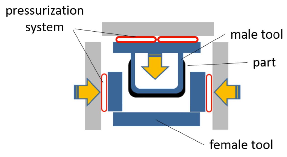
GKN Fokker tools for out-of-autoclave (OOA) consolidation of thermoplastic composite (TPC) parts feature integrated heating and cooling and use bladders (shown in red) to apply pressure.
In parallel, GKN Fokker developed a novel out-of-autoclave (OOA) consolidation process for beams and spars up to 6 meters long. “We currently manufacture TPC spars of this size that we would like to produce without an autoclave,” explains Offringa. “OOA consolidation reduces cycle time as well as the amount of energy and auxiliary materials needed. We had previously developed this technology for wing ribs [see “Wing of Tomorrow ribs: One-shot, thermoplastic, OOA consolidation”], but wanted to scale it for larger parts.”
To do this, GKN Fokker developed tools with integrated pressure, heating and cooling systems, and used these in a specially designed consolidation press built by Mikrosam.
Integrated tools
“You often see these integrated tools used with resin transfer molding [RTM],” says Offringa. RTM is a molding process where liquid resin — traditionally a thermoset resin such as epoxy — is injected into a dry fiber preform and then cured with pressure and heat in an RTM press. GKN Fokker isn’t using liquid or thermoset resins, but it is using these integrated tools to apply temperature and pressure to consolidate TPC preforms. Notably, the TPC parts GKN Fokker manufactures may compete with RTM to achieve higher production rates in composite aerostructures.
In the GKN Fokker OOA consolidation tools, explains Offringa, “water is used for cooling and conventional systems or induction can be used for heating the tool surface in contact with the TPC preform. Cool-down is more important than heating up. If cooling isn’t homogeneous over the whole surface of the part, then you will get shrinkage first on one side and then on the other and that will cause defects in the part.”
Although induction heating is practically instantaneous and very energy-efficient for high-temperature heating, do such systems present any challenges during cool-down? “The induction heating is indeed very fast and cooling is a bit tricky and must be controlled in combination with the tooling design,” says Offringa.
Novel press and bladder
GKN Fokker’s OOA-integrated tools are placed within a novel press supplied by Mikrosam. “This is the first custom-engineered press we’ve built,” says Samak. “Presses are usually not our core business, but we do have good engineering and the GKN team saw that we could work with them to build a very custom press where they can integrate their own heating and cooling mechanisms.”
“The press is like a 6-meter-long steel box,” says Offringa. “And in that box, you can you put your tool with its own heating, cooling and pressurization. It's a modular system for manufacturing all sorts of parts. And for pressurization, we are using a bladder system.”
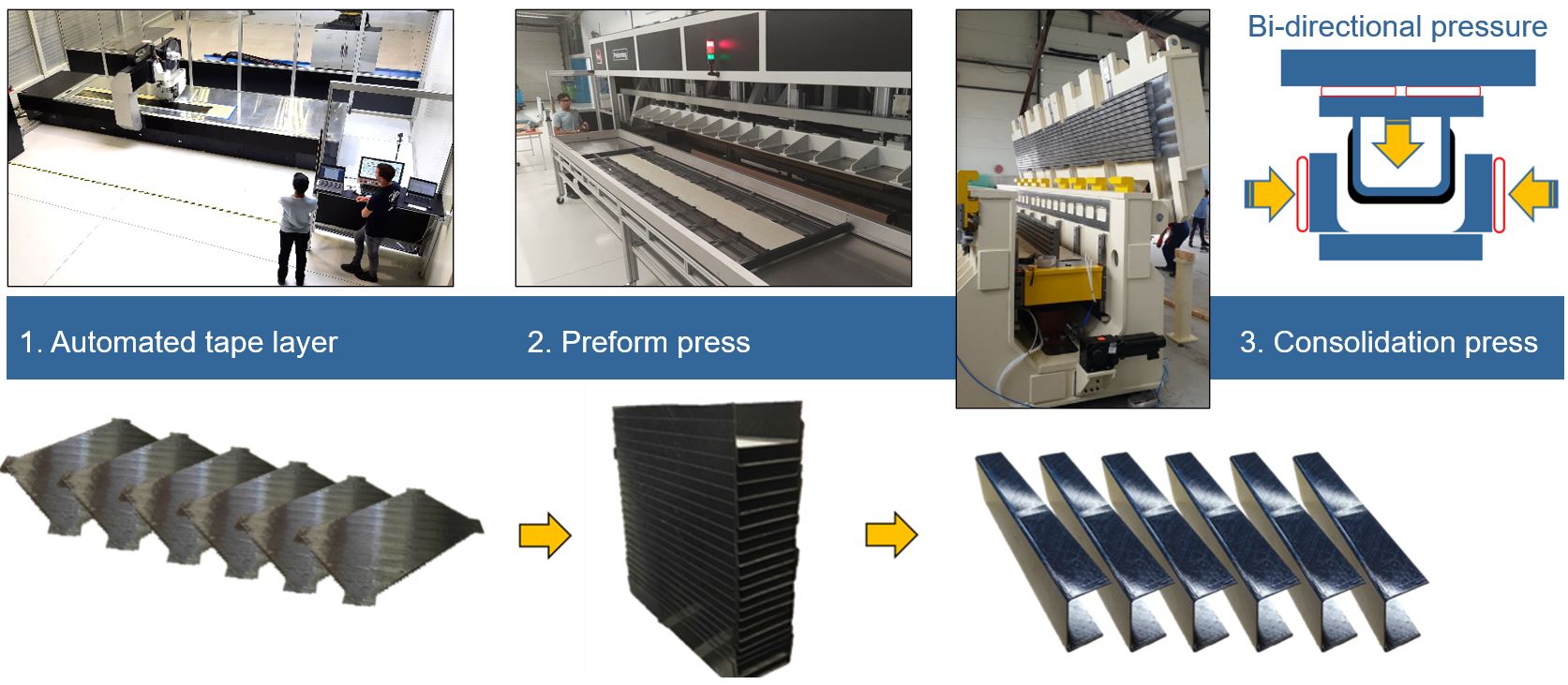
Fig. 5. OOA process chain for future TPC spars. In the LIFT project, GKN Fokker produced a TPC spar for the V-tail of demonstrator tiltrotor aircraft using the process chain shown above. Flat tailored blanks were produced using an automated tape laying (ATL) system with an integrated ultrasonic tacking machine. Those blanks were then preformed into C-shapes using a simple preforming press and then placed into the Mikrosam consolidation press to produce the final part.
Using a bladder or membrane to apply pressure during TPC molding and consolidation is not new. In the 2021 article, “Hydrostatic membrane consolidation: Skin-stringer panels in 60 minutes,” Airbus Operations (Hamburg, Germany), Airbus subsidiary Composites Technology Center (CTC, Stade, Germany) and press production line supplier Siempelkamp (Krefeld, Germany) demonstrated consolidation of a CF/PAEK UD tape composite skin while integrating stringer preforms of the same material in less than 70 minutes (30-minute ramp up, 10-minute hold and 30-minute cooldown). The project used a stainless steel membrane with oil behind it to exert hydrostatic pressure on the assembly’s top surface, replacing the upper part of a 2-piece matched steel mold. That tool set was placed into a conventional vertical action press which then applied heat and pressure.
That 2021 article also discussed thermoforming of CF/polyetherketoneketone (PEKK) UD tape into a demonstrator rib in the RApid high-Performance Manufacturing (RAPM) program led by Boeing (Chicago, Ill., U.S.):
“The tooling approach developed used a thin aluminum bladder that was pressurized with inert gas at high temperatures, expanding to apply even pressure to all of the part’s surfaces during stamping. This made it possible to maintain hydrostatic pressure horizontally against the part’s vertical flanges while using a press that lacked horizontal hydraulic system and controls and thus acted only in the vertical direction.”
How does the GKN Fokker process differ? “Our press is a simple concept,” says Offringa, “similar to latching a door shut, basically. It is not a huge pneumatic or hydraulic press, but closer to what Coexpair [Namur, Belgium] does with its RTM presses built using a license from Radius Engineering [Salt Lake City, Utah, U.S.].” Note that Coexpair supplied the RTM presses used in Spirit AeroSystems’ high-rate production of composite spoilers in Prestwick, Scotland, for the Airbus A320 (see “High-rate, automated RTM line delivers next-gen spoilers”). “Coexpair recently supplied a 12-meter RTM press,” adds Offringa, “which is a bit like the one built for us by Mikrosam, but which uses a different system of opening and closing. And they’re very cost-effective.”
“So, our press is very simple and the bladder is very simple,” he continues. “It isn’t metal, but is more like a fire hose, flexible and designed to withstand pressure. You place the preform in the tool with the bladder system and close the press with a simple action at the top, and it can apply 10-15 bar of pressure all over the preform. And in that press, we have hardly any movement, yet pressure is applied from the top and sides.”
“This system is also modular,” notes Samak, “which provides a lot of flexibility for future production.”
Future TPC structures production
Thus, not only has the MFFD floor beams project played a part in advancing large, welded TPC airframe modules, it has also laid the foundation for GKN Fokker to more efficiently produce ever larger TPC aerostructures (Fig. 5). “We make rudders and elevators for business jets in our factory here in the Netherlands,” says Offringa. “The elevators are 6 meters long and they have spars today that previously have been vacuum bagged and autoclave cured. Now, however, we are moving this to OOA which eliminates vacuum bagging man-hours and materials and cuts cycle time by 80%.”
This more sustainable production of TPC structures has been further advanced in a second Clean Aviation project called LIFT, where GKN Fokker worked with Leonardo Helicopters (Cascina Costa di Samarate, Italy) to produce a TPC tail structure for a flying tiltrotor aircraft. “This tail structure is also made using AFP and has a simple C-shaped structural member,” says Offringa. “We produced this spar using a process chain that we have installed in the GTC-NL. We first made a flat blank using an automated tape laying [ATL] machine that tacked the plies together with an ultrasonic tacking system. We then used a simple, servo-controlled preforming press. The ATL system and preforming press are from Boikon [Leek, Netherlands]. Finally, we placed the preform into the Mikrosam consolidation press, which produces the final TPC part.”
So, what are GKN Fokker’s next steps? “To expand the OOA forming and co-consolidation technology to more challenging applications,” says Offringa, “such as complex spars and beams as well as integrally stiffened skins.”


Related Content

TU Munich develops cuboidal conformable tanks using carbon fiber composites for increased hydrogen storage
Flat tank enabling standard platform for BEV and FCEV uses thermoplastic and thermoset composites, overwrapped skeleton design in pursuit of 25% more H2 storage.
Read More
The potential for thermoplastic composite nacelles
Collins Aerospace draws on global team, decades of experience to demonstrate large, curved AFP and welded structures for the next generation of aircraft.
Read More
Cycling forward with bike frame materials and processes
Fine-tuning of conventional materials and processes characterizes today’s CFRP bicycle frame manufacturing, whether in the large factories of Asia or at reshored facilities in North America and Europe. Thermoplastic resins and automated processes are on the horizon, though likely years away from high-volume production levels.
Read More
Jeep all-composite roof receivers achieve steel performance at low mass
Ultrashort carbon fiber/PPA replaces steel on rooftop brackets to hold Jeep soft tops, hardtops.
Read MoreRead Next

Optimizing AFP for complex-cored CFRP fuselage
Automated process cuts emissions, waste and cost for lightweight RACER helicopter side shells.
Read More
From the CW Archives: The tale of the thermoplastic cryotank
In 2006, guest columnist Bob Hartunian related the story of his efforts two decades prior, while at McDonnell Douglas, to develop a thermoplastic composite crytank for hydrogen storage. He learned a lot of lessons.
Read More
CW’s 2024 Top Shops survey offers new approach to benchmarking
Respondents that complete the survey by April 30, 2024, have the chance to be recognized as an honoree.
Read More