
Materials & Processes: Fabrication methods
There are numerous methods for fabricating composite components. Selection of a method for a particular part, therefore, will depend on the materials, the part design and end-use or application. Here's a guide to selection.
- Wind/Energy
- Sustainability
- Automotive
- Sheet Molding Compound
- Pultrusion
- Defense
- Out of Autoclave
- Workforce Development
- Market Outlook
- Pressure Vessels
- Adhesives
- ATL/AFP
- Weaving
- Consumer
- Processes
- Aerospace
- Mass Transit
- Markets
- Marine
- Injection/Overmolding
- Autoclave
- Construction
- Compression Molding
- Ketones
- Additive Manufacturing
- Composites Basics
- RTM
- Curing
- Infusion
- BMI
- Filament Winding


There are numerous methods for fabricating composite components. Some methods have been borrowed (injection molding from the plastic industry, for example), but many were developed to meet specific design or manufacturing challenges faced with fiber-reinforced polymers. Selection of a method for a particular part, therefore, will depend on the materials, the part design and end-use or application. (See “Part design criteria,”).
Composite fabrication processes typically involve some form of molding, to shape the resin and reinforcement. A mold tool is required to give the unformed resin/fiber combination its shape prior to and during cure. Click on “Tooling” for an overview of mold types as well as materials and methods used to make mold tools.


The most basic fabrication method for thermoset composites is hand layup, which typically consists of placing layers, called plies of either dry fabrics, or prepreg (fabric pre-impregnated with resin), by hand onto a tool to form a laminate stack. Resin is applied to the dry plies after layup is complete (e.g., by means of resin infusion). In a variation known as wet layup, each ply is coated with resin and debulked (compacted) after it is placed. Although debulk can be done by hand with rollers, most fabricators today use a vacuum-bagging technique that involves placing plastic sheet materials over the layup, sealing it at the tool’s edges, adding one or more ports for air hoses and then evacuating air from the space between the sheet and the layup using a vacuum pump). Debulking not only consolidates the layup but also removes air trapped in the resin matrix that would otherwise create undesirable voids (air pockets) in the laminate that could weaken the composite.
Several curing methods are available. The most basic is simply to allow cure (intiated by a catalyst or hardener additive premixed into the resin) to occur at room temperature. Cure can be accelerated, however, by applying heat, typically with an oven, and pressure, by means of a vacuum. For the latter, a vacuum bag, with breather assemblies, is placed over the layup and attached to the tool (in similar fashion to that used in debulking), then a vacuum is pulled prior to initiation of cure. The vacuum bagging process here further consolidates the plies of material and significantly reduces voids due to the off-gassing that occurs as the matrix progresses through its chemical curing stages.
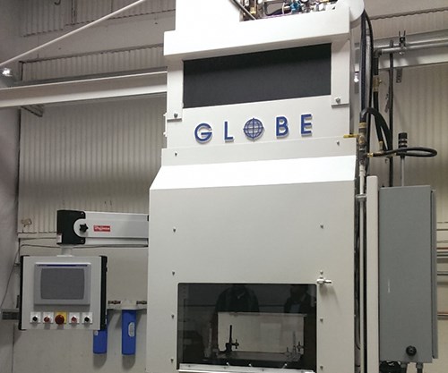
In November 2014, Globe Machine Manufacturing Co. (Tacoma, WA, US) trialed its second-generation RapidClave system, a hybrid out-of-autoclave molding process that successfully formed unidirectional carbon fiber/epoxy prepreg (6-8 plies, 0°/90° layup) parts in a 6-minute cycle, a first for thermoset composites and a huge step closer to mass-production expectations in the auto industry. Read more: https://www.compositesworld.com/articles/sub-8-minute-cycle-times-on-carbonepoxy-prepreg
Pressure. Many high-performance thermoset parts require heat and high consolidation pressure to cure — conditions that require the use of an autoclave. Autoclaves, generally, are expensive to buy and operate. Manufacturers that are equipped with autoclaves usually cure a number of parts simultaneously. Computer systems monitor and control autoclave temperature, pressure, vacuum and inert atmosphere, which allows unattended and/or remote supervision of the cure process and maximizes efficient use of the technique.
Heat. When heat is required for cure, the part temperature is “ramped up” in small increments, maintained at cure level for a specified period of time defined by the resin system, then “ramped down” to room temperature, to avoid part distortion or warp caused by uneven expansion and contraction. When this curing cycle is complete and after parts are demolded, some parts go through a secondary freestanding postcure, during which they are subjected for a specific period of time to a temperature higher than that of the initial cure to enhance chemical crosslink density.
Alternative curing methods. Electron-beam (E-beam) curing has been explored as an efficient curing method for thin laminates. In E-beam curing, the composite layup is exposed to a stream of electrons that provide ionizing radiation, causing polymerization and crosslinking in radiation-sensitive resins. X-ray and microwave curing technologies work in a similar manner. A fourth alternative, ultraviolet (UV) curing, involves the use of UV radiation to activate a photoinitiator added to a thermoset resin, which, when activated, sets off a crosslinking reaction. UV curing requires light-permeable resin and reinforcements.
Cure monitoring. An emerging technology is the monitoring of the cure itself. Dielectric cure monitors measure the extent of cure by gauging the conductivity of ions — small, polarized, relatively insignificant impurities that are resident in resins. Ions tend to migrate toward an electrode of opposite polarity, but the speed of migration is limited by the viscosity of the resin — the higher the viscosity, the slower the speed. As crosslinking proceeds during cure, resin viscosity increases. Other methods include dipole monitoring within the resin, the monitoring of micro-voltage produced by the crosslinking, monitoring of the exothermic reaction in the polymer during cure and, potentially, the use of infrared monitoring via fiber-optic technology (see "Monitoring the cure itself.”)
Out-of-autoclave (OOA) curing is a notable phenomenon gaining momentum in the industry for high-performance composite components. The high cost and limited size of autoclave systems has prompted many processors, particularly in aerospace, to call for OOA resins that can be cured with heat only in an oven (less capital-intensive and less expensive to operate than an autoclave, particularly with very large parts), or at room temperature. Cytec Aerospace Materials (now Solvay Composite Materials) introduced the first OOA resin, an epoxy designed for aerospace applications. OOA tooling epoxies and adhesives also are coming to market (see “Autoclave quality outside the autoclave?”)
Open molding
Open contact molding in one-sided molds is a low-cost, common process for making fiberglass composite products. Typically used for boat hulls and decks, RV components, truck cabs and fenders, spas, bathtubs, shower stalls and other relatively large, noncomplex shapes, open molding involves either hand layup or a semi-automated alternative, sprayup.
In an open-mold sprayup application, the mold is first treated with mold release. If a gel coat is used, it is typically sprayed into the mold after the mold release has been applied. The gel coat then is cured and the mold is ready for fabrication to begin. In the sprayup process, catalyzed resin (viscosity of 500-1,000 cps) and glass fiber are sprayed into the mold using a chopper gun, which chops continuous fiber into short lengths, then blows the short fibers directly into the sprayed resin stream so that both materials are applied simultaneously. To reduce VOCs, piston pump-activated, non-atomizing spray guns and fluid-impingement spray heads dispense gel coats and, after gel coat cure, resins in larger droplets at low pressure. Another option is a roller impregnator, which pumps resin into a roller similar to a paint roller.
In the final steps of the sprayup process, workers compact the laminate by hand with rollers. Wood, foam or other core material may then be added, and a second sprayup layer imbeds the core between the laminate skins. The part is then cured, cooled and removed from the typically reusable mold.
Hand layup and sprayup methods are often used in tandem to reduce labor. For example, fabric might first be placed in an area exposed to high stress; then, a spray gun might be used to apply chopped glass and resin to build up the rest of the laminate. Balsa or foam cores may be inserted between the laminate layers in either process. Typical glass fiber volume is 15% with sprayup and 25% with hand layup.
Sprayup processing, once a very prevalent manufacturing method, has begun to fall out of favor. Federal regulations in the U.S. and similar rules in the EU have mandated limits on worker exposure to, and emission into the environment of VOCs and hazardous air pollutants (HAPs). Styrene, the most common monomer used as a diluent in thermoset resins, is on both lists. Because worker exposure to and emission of styrene is difficult and expensive to control in the sprayup process, many composites manufacturers have migrated to closed mold, infusion-based processes, which better contain and manage styrenes.
Although open molding via hand layup is being replaced by faster and more technically precise methods (as the following makes clear), it is still widely used in the repair of damaged parts, including parts made form other commonly used materials, such as steel and concrete. For more information, click on “Composites for repair.”
Resin infusion processes
Ever-increasing demand for faster production rates has pressed the industry to replace hand layup with alternative fabrication processes and has encouraged fabricators to automate those processes wherever possible.
A common alternative is resin transfer molding (RTM), sometimes referred to as liquid molding. RTM is a fairly simple process: It begins with a two-part, matched, closed mold that is made of either metal or composite material. Dry reinforcement (typically a preform) is placed into the mold and the mold is closed. Resin and catalyst are metered and mixed in dispensing equipment, then pumped into the mold under low to moderate pressure through injection ports, following predesigned paths through the preform. Extremely low-viscosity resin is used in RTM applications, especially with for thick parts, to ensure that the resin permeates the preform quickly and thoroughly before the onset of cure. Both mold and resin can be preheated, as necessary, for particular applications.
RTM produces high-quality parts without the necessity of an autoclave. However, when cured and demolded, a part destined for a high-temperature application usually undergoes postcure.
Most RTM applications use a two-part epoxy formulation. The two parts are mixed just before they are injected. Bismaleimide and polyimide resins also are available in RTM formulations.
Light RTM is a variant of RTM that is growing in popularity. In Light RTM, low injection pressure, coupled with vacuum, allow the use of less-expensive, lightweight two-part molds or a very lightweight, flexible upper mold.
The benefits of RTM are impressive. Generally, the dry preforms and resins used in RTM are less expensive than prepreg material and can be stored at room temperature. The process can produce thick, near-net shape parts, eliminating most post-fabrication work. It also yields dimensionally accurate complex parts with good surface detail and, unlike open molding techniques, which typically yield a contoured but planar part with A nd B sides (finished and unfinished surfaces, respectively) RTM can deliver a desired cosmetic finish on all exposed surfaces of complex, three-dimensional components. It is also possible to place inserts inside the preform before the mold is closed, allowing the RTM process to accommodate core materials and integrate “molded in” fittings and other hardware into the part structure. Moreover, void content on RTM’d parts is low, measuring ≤2%. Finally, RTM significantly cuts cycle times and can be adapted for use as one stage in an automated, repeatable manufacturing process for even greater efficiency, reducing cycle time from what can be several days, typical of hand layup, to just hours — or even minutes.
A recent variant of RTM, called high-pressure RTM (HP-RTM), is gaining attention for its potential to quickly produce automotive parts. Typically designed into a completely automated system that includes mold shuttles, HP-RTM’s ability to rapidly fill a mold loaded with a preform with a very fast curing resin shows promise for high production. HP-RTM still comprises a fiber preform, a closed mold, a press and a resin injection system, but the latter is now an impingement mixing head, like that first developed for polyurethane (PU) foam applications in the 1960s. In fact, metering/mixing/injection suppliers for the PU and reaction injection molding (RIM, see next item) processes were among the early developers of HP-RTM, including KraussMaffei Technologies GmbH (Munich, Germany), Hennecke Inc. (Sankt Augustin, Germany), Frimo Inc. (Lotte, Germany) and Cannon USA Inc. and Cannon SpA (Cranberry Township, PA US and Borromeo, Italy).
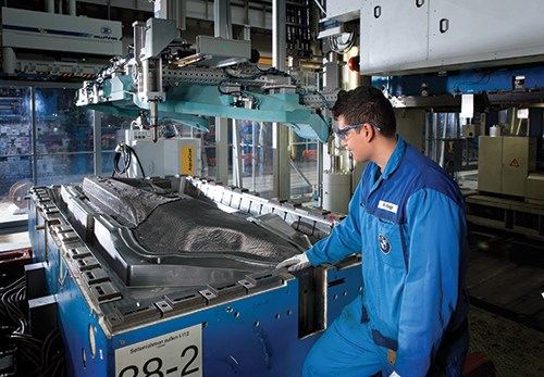
Molding complex parts at high volume: A variant of resin transfer molding (RTM), high-pressure RTM (HP-RTM), is already used in series production of large, integrated CFRP auto components, such as this BMW (Wolfsburg, Gemany) i8 sportster's sideframe.Read the full article: https://www.compositesworld.com/articles/the-rise-of-hp-rtm
In contrast to RTM, where resin and catalyst are premixed prior to injection under pressure into the mold, reaction injection molding (RIM) injects a rapid-cure resin and a catalyst into the mold in two separate streams. Mixing, and the resulting chemical reaction, occur in the mold instead of in a dispensing head. Automotive industry suppliers have combined structural RIM (SRIM) with rapid preforming methods to fabricate structural parts that don’t require a Class A finish. Programmable robots have become a common means to spray a chopped fiberglass/binder combination onto a vacuum-equipped preform screen or mold. Robotic sprayup can be directed to control fiber orientation. A related technology, dry fiber placement, combines stitched preforms and RTM. Fiber volumes of up to 68% are possible, and automated controls ensure low voids and consistent preform reproduction, without the need for trimming.
Vacuum-assisted resin transfer molding (VARTM) refers to a variety of related processes that represent a still fastest-growing molding technology. The salient difference between VARTM-type processes and RTM is that in VARTM, resin is drawn into a preform through use of a vacuum only, rather than pumped in under pressure. VARTM does not require high heat or pressure. For that reason, VARTM operates with low-cost tooling, making it possible to inexpensively produce large, complex parts in one shot.
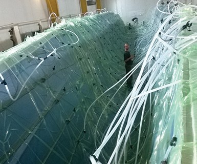
Vacuum infusion has found significant application in boatbuilding, because it permits fabricators to infuse entire hulls, deck structures and planar contoured parts in a single step. But aerospace structures, another group of often large parts, are also being developed using vacuum infusion processes. Read the full article: https://www.compositesworld.com/articles/dark-knights-sleek-trimarans-surveil-the-seas
In the VARTM process, fiber reinforcements are placed in a one-sided mold, and a cover (typically a plastic bagging film) is placed over the top to form a vacuum-tight seal. The resin typically enters the structure through strategically placed ports and feed lines, termed a “manifold.” It is drawn by vacuum through the reinforcements by means of a series of designed-in channels that facilitate wetout of the fibers. Fiber content in the finished part can run as high as 70%. Current applications include marine, ground transportation and infrastructure parts.
Resin infusion has found significant application in boatbuilding, because it permits fabricators to infuse entire hulls, deck structures and planar contoured parts in a single step. But aerospace structures, another group of often large parts, are also being developed using VARTM.
One resin-infusion twist is the use of two bags, termed double-bag infusion, which uses one vacuum pump attached to the inner bag to extract volatiles and entrapped air, and a second vacuum pump on the outer bag to compact the laminate. This method has been employed by The Boeing Co. (Chicago, IL, US) and NASA, as well as small fabricating firms, to produce aerospace-quality laminates without an autoclave. Aerospace quality has also been achieved in the development of an out-of-autoclave (OOA) CFRP wing for the MS-21 single-aisle jetliner produced by Russian OEM Irkut and fabricator Aerocomposit, both based in Moscow. A key step was FACC AG’s (Ried im Innkreis, Austria) award-winning development of an integral CFRP wing box using its proprietary membrane assisted resin infusion (MARI) process, which uses a semipermeable membrane to enable a consistent, robust process delivering 100% impregnation (no dry spots or voids). OOA infusion has also been demonstrated on large tooling and structures for NASA’s Space Launch System (SLS) program using epoxy and bismaleimide (BMI) resins and similar work with benzoxazine resins is moving apace.
Resin film infusion (RFI) is a hybrid process in which a dry preform is placed in a mold on top of a layer, or interleaved with multiple layers, of high-viscosity resin film. Under applied heat, vacuum and pressure, the resin liquefies and is drawn into the preform, resulting in uniform resin distribution, even with high-viscosity, toughened resins, because of the short flow distance.
High-volume molding methods
Compression molding is a high-volume thermoset molding process that employs expensive but very durable metal dies. It is an appropriate choice when production quantities exceed 10,000 parts. As many as 200,000 parts can be turned out on a set of forged steel dies, using sheet molding compound (SMC), a composite sheet material made by sandwiching chopped fiberglass between two layers of thick resin paste. To form the sheet, the resin paste transfers from a metering device onto a moving film carrier. Chopped glass fibers drop onto the paste, and a second film carrier places another layer of resin on top of the glass. Rollers compact the sheet to saturate the glass with resin and squeeze out entrapped air. The resin paste initially is the consistency of molasses (20,000-40,000 cps); over the next three to five days, its viscosity increases and the sheet becomes leather-like (about 25 million cps), ideal for handling.
When the SMC is ready for molding, it is cut into smaller sheets and the charge pattern (ply schedule) is assembled on a heated mold (121°C to 262°C). The mold is closed and clamped, and pressure is applied at 24.5 to 172.4 bar. As material viscosity drops, the SMC flows to fill the mold cavity. After cure, the part is demolded manually or by integral ejector pins.
A typical low-profile (less than 0.05% shrinkage) SMC formulation for a Class A finish consists, by weight, of 25% polyester resin, 25% chopped glass, 45% fillers and 5 percent additives. Fiberglass thermoset SMC cures in 30-150 seconds and overall cycle time can be as low as 60 seconds. Other grades of SMC include low-density, flexible and pigmented formulations. Low-pressure SMC formulations that are now on the market offer open molders low-capital-investment entry into closed-mold processing with near-zero VOC emissions and the potential for very high-quality surface finish.
Automakers are exploring carbon fiber-reinforced SMC, hoping to take advantage of carbon’s high strength- and stiffness-to-weight ratios in exterior body panels and other parts. Newer, toughened SMC formulations help prevent microcracking, a phenomenon that previously caused paint “pops” during the painting process (surface craters caused by outgassing, the release of gasses trapped in the microcracks during oven cure).
Composites manufacturers in industrial markets are formulating their own resins and compounding SMC in-house to meet needs in specific applications that require UV, impact and moisture resistance and have surface-quality demands that drive the need for customized material development.
Injection molding is a fast, high-volume, low-pressure, closed process using, most commonly, filled thermoplastics, such as nylon with chopped glass fiber. In the past 20 years, however, automated injection molding of BMC has taken over some markets previously held by thermoplastic and metal casting manufacturers. For example, the first-ever BMC-based electronic throttle control (ETC) valves (previously molded only from die-cast aluminum) debuted on engines in the BMW Mini and the Peugeot 207, taking advantage of dimensional stability offered by a specially-formulated BMC supplied by TetraDUR GmbH (Hamburg, Germany), a subsidiary of Bulk Molding Compounds Inc. (BMCI, West Chicago, IL, US).
In the BMC injection molding process, a ram- or screw-type plunger forces a metered shot of material through a heated barrel and injects it (at 34.47-82.74 MPa) into a closed, heated mold. In the mold, the liquefied BMC flows easily along runner channels and into the closed mold. After cure and ejection, parts need only minimal finishing. Injection speeds are typically one to five seconds, and as many as 2,000 small parts can be produced per hour in some multiple-cavity molds.
Parts with thick cross-sections can be compression molded or transfer molded with BMC. Transfer molding is a closed-mold process wherein a measured charge of BMC is placed in a pot with runners that lead to the mold cavities. A plunger forces the material into the cavities, where the product cures under heat and pressure.
Hybrid injection-molding/thermoforming is one example of the automotive industry’s quest for short mold cycles (<2 minutes) by mixing plastics and composites processes. SpriForm — a process developed by HBW-Gubesch Thermoforming GmbH (Wilhelmsdorf, Germany) and used in the CAMISMA auto seat back project led by Johnson Controls (JCI, Burscheid, Germany) — preheats tailored blanks made from carbon fiber (CF)-reinforced polyamide 12 (PA12) organosheets, compression molds them in a matched metal die and tool, and then injection molds a 30% short glass fiber-reinforced PA12 compound that fills the mold cavity to create fully overmolded edges as well as ribs and other functional elements. The process is easily automated using two robots and achieves a 40-50% weight savings vs. a steel seat back and adds less than US$5/kg incremental cost for weight saved. Though continuous CF/PA12 tapes provide tailored stiffness and strength, lower cost injection molding material makes up half of the seat back mass. The one-shot process takes roughly 90 seconds, producing a geometrically detailed part with no secondary operations. The base layer of the organosheet preform was a PA12-impregnated mat made from recycled carbon fiber (RCF), also a means for lowering part cost and carbon footprint. (Read more by clicking on “CAMISMA’s car seat back: Hybrid composite for high volume.”)
Filament winding is a continuous fabrication method that can be highly automated and repeatable, with relatively low material costs. A long, cylindrical tool called a mandrel is suspended horizontally between end supports, while the “head” — the fiber application instrument — moves back and forth along the length of a rotating mandrel, placing fiber onto the tool in a predetermined configuration. Computer-controlled filament-winding machines are available, equipped with from 2 to 12 axes of motion.
In most thermoset applications, the filament winding apparatus passes the fiber material through a resin “bath” just before the material touches the mandrel. This is called wet winding. However, a variation uses towpreg, that is, continuous fiber pre-impregnated with resin. This eliminates the need for an onsite resin bath. In a slightly different process, fiber is wound without resin (dry winding). The dry shape is then used as a preform in another molding process, such as RTM.
Following oven or autoclave curing, the mandrel either remains in place to become part of the wound component or, typically, it is removed. One-piece cylindrical or tapered mandrels, usually of simple shape, are pulled out of the part with mandrel extraction equipment. Some mandrels, particularly in more complex parts, are made of soluble material and may be dissolved and washed out of the part. Others are collapsible or built from several parts that allow its disassembly and removal in smaller pieces. Filament-winding manufacturers often “tweak” or slightly modify off-the-shelf resin to meet specific application requirements. Some composite part manufacturers develop their own resin formulations.
In thermoplastics winding, all material is in prepreg form, so a resin bath is not needed. Material is heated as it is wound onto the mandrel — a process known as curing “on the fly” or in-situ consolidation. The prepreg is heated, layed down, compacted, consolidated and cooled in a single, continuous operation. Thermoplastic prepregs eliminate autoclave curing (cutting costs and size limitations) and reduce raw material costs, and the resulting parts can be reprocessed to correct flaws.
Filament winding yields parts with exceptional circumferential or “hoop” strength. The highest-volume single application of filament winding is golf club shafts. Fishing rods, pipe, pressure vessels and other cylindrical parts comprise most of the remaining business.
Pultrusion, like RTM, has been used for decades with glass fiber and polyester resins, but in the last 10 years the process also has found application in advanced composites applications. In this relatively simple, low-cost, continuous process, the reinforcing fiber (usually roving, tow or continuous mat) is typically pulled through a heated resin bath and then formed into specific shapes as it passes through one or more forming guides or bushings. The material then moves through a heated die, where it takes its net shape and cures. Further downstream, after cooling, the resulting profile is cut to desired length. Pultrusion yields smooth finished parts that typically do not require postprocessing. A wide range of continuous, consistent, solid and hollow profiles are pultruded, and the process can be custom-tailored to fit specific applications.
Tube rolling is a longstanding composites manufacturing process that can produce finite-length tubes and rods. It is particularly applicable to small-diameter cylindrical or tapered tubes in lengths as great as 6.2m. Tubing diameters up to 152 mm can be rolled efficiently. Typically, a tacky prepreg fabric or unidirectional tape is used, depending on the part. The material is precut in patterns that have been designed to achieve the requisite ply schedule and fiber architecture for the application. The pattern pieces are laid out on a flat surface and a mandrel is rolled over each one under applied pressure, which compacts and debulks the material. When rolling a tapered mandrel — e.g., for a fishing rod or golf shaft — only the first row of longitudinal fibers falls on the true 0° axis. To impart bending strength to the tube, therefore, the fibers must be continuously reoriented by repositioning the pattern pieces at regular intervals.
Automated fiber placement (AFP). The fiber placement process automatically places multiple individual prepreg tows onto a mandrel at high speed, using a numerically controlled, articulating robotic placement head to dispense, clamp, cut and restart as many as 32 tows simultaneously. Minimum cut length (the shortest tow length a machine can lay down) is the essential ply-shape determinant. The fiber placement heads can be attached to a 5-axis gantry, retrofitted to a filament winder or delivered as a turnkey custom system. Machines are available with dual mandrel stations to increase productivity. Advantages of fiber placement include processing speed, reduced material scrap and labor costs, parts consolidation and improved part-to-part uniformity. Often, the process is used to produce large thermoset parts with complex shapes.
Automated tape laying (ATL) is an even speedier automated process in which prepreg tape, rather than single tows, is laid down continuously to form parts. It is often used for parts with highly complex contours or angles. Tape layup is versatile, allowing breaks in the process and easy direction changes, and it can be adapted for both thermoset and thermoplastic materials. The head includes a spool or spools of tape, a winder, winder guides, a compaction shoe, a position sensor and a tape cutter or slitter. In either case, the head may be located on the end of a multiaxis articulating robot that moves around the tool or mandrel to which material is being applied, or the head may be located on a gantry suspended above the tool. Alternatively, the tool or mandrel can be moved or rotated to provide the head access to different sections of the tool. Tape or fiber is applied to a tool in courses, which consist of one row of material of any length at any angle. Multiple courses are usually applied together over an area or pattern and are defined and controlled by machine-control software that is programmed with numerical input derived from part design and analysis. Capital expenditures for computer-driven, automated equipment can be significant.
Although ATL generally is faster than AFP and can place more material over longer distances, AFP is better suited to shorter courses and can place material more effectively over contoured surfaces. These technologies grew out of the machine tool industry and have seen extensive use in the manufacture of the fuselage, wingskin panels, wingbox, tail and other structures on the forthcoming Boeing 787 Dreamliner and the Airbus A350 XWB. ATL and AFP also are used extensively to produce parts for the F-35 Lightning II fighter jet the V-22 Osprey tiltrotor troop transport and a variety of other aircraft. The latest equipment trend enables both AFP and ATL, switching between in a matter of minutes by swapping out dockable heads. Another development area is the pursuit of out of autoclave (OOA) primary CFRP aircraft structures via high-performance thermoplastics. Airbus (Toulouse, France) is working with both FIDAMC (Madrid, Spain) supported by MTorres (Navarra, Spain) and Technocampus EMC2 (Nantes, France) supported by Coriolis Composites SAS (Queven, France) to develop stringer-stiffened fuselage skin panels which are places and in situ cured via laser using automated machinery. FIDAMC and MTorres announced at JEC 2014 a CF/polyetheretherketone (PEEK) fuselage panel achieving 35-40% crystallinity in the matrix and a degree of consolidation (DOC) sufficient to require no further heat, vacuum bag or autoclave processing. Real-time temperature control is being integrated into the equipment. Materials have been supplied by Cytec Aerospace Materials HQ (Woodland Park, NJ, US) and Toho Tenax Europe GmbH (Wuppertal, Germany).
Centrifugal casting of pipe from 25 mm to 356 mm in diameter is an alternative to filament winding for high-performance, corrosion-resistant service. In cast pipe, 0°/90° woven fiberglass provides both longitudinal and hoop strength throughout the pipe wall and brings greater strength at equal wall thickness compared to multiaxial fiberglass wound pipe. In the casting process, epoxy or vinyl ester resin is injected into a 150G centrifugally spinning mold, permeating the woven fabric wrapped around the mold’s interior surface. The centrifugal force pushes the resin through the layers of fabric, creating a smooth finish on the outside of the pipe, and excess resin pumped into the mold creates a resin-rich, corrosion- and abrasion-resistant interior liner.
Fiber-reinforced thermoplastic components now can be produced by extrusion, as well. Breakthrough material and process technology has been developed with long-fiber glass-reinforced thermoplastic (ABS, PVC or polypropylene) composites to provide profiles that offer a tough, low-cost alternative to wood, metal and injection-molded plastic parts used in office furniture, appliances, semitrailers and sporting goods. A huge market has emerged in the past decade for extruded thermoplastic/wood flour (or other additives, such as bast fibers or fly ash) composites. These wood plastic composites, or WPCs, used to simulate wood decking, siding, window and door frames, and fencing.
Additive manufacturing
Also known as 3D printing, this more recent form of composite part production grew out of efforts to reduce the costs in the design-to-prototype phase of product development, taking aim particularly at the material-, labor- and and time-intensive area of toolmaking. Additive manufacturing is a step change in the development of rapid prototyping concepts that were introduced more than 20 years ago — a collection of similar, but separately developed additive fabrication technologies — that is, automated processes that assemble a three-dimensional (3D) object from a series of nominally two-dimensional (2D), cross-sectional layers of specialized materials.
All additive fabrication techniques begin with a CAD drawing. Solid-model CAD data is converted, using special software, into a file format that represents a 3D surface as an assembly of planar triangles. Additional, and typically proprietary, software then is used to “slice” this virtual image into very thin 2D cross-sectional patterns. This layer data is used to instruct additive fabrication machinery as it builds a 3D physical model by “stacking” the 2D slices.
Today, five additive fabrication methods are in use:
Stereolithography (SLA), patented in 1986, was the first fully commercial rapid prototyping technology and is still the most widely used. In the SLA process, the part model is built on a platform positioned just below the surface in a vat of liquid, photocurable polymer, usually an epoxy or acrylate resin. A low-powered ultraviolet (UV) laser, programmed with the previously created CAD slice data, traces out the first layer of the part with its highly focused UV light beam, scanning and curing the resin within the boundaries of the slice outline until the entire area within the slice cross section is solidified. An elevator then incrementally lowers the platform into the liquid polymer to a depth equal to the slice thickness, and a sweeper recoats the solidified layer with liquid polymer. The laser then traces out a second layer on top of the first. The process is repeated until the part is complete. Depending on the geometry of the part, mechanical supports may need to be built into the part during the build to contain the liquid. After removal from the vat, supports are removed from the part, which then is placed in an UV oven for additional curing.
Fused Deposition Modeling (FDM), is the second most widely used AM process. FDM builds parts of ABS (acrylonitrile butadiene styrene), polycarbonate and other resins noted for toughness. Often, it is chosen when part durability is paramount.
FDM builds a 3-D object one layer at a time. A plastic filament is unwound from a coil, supplying material to a heated extrusion nozzle, which controls the flow. The nozzle is mounted over a mechanical stage, and can be moved horizontally and/or vertically. The nozzle moves over the stage, which is coated with a support material, depositing a thin bead of extruded plastic. For ABS, the thickness of that layer is typically 0.25 mm/0.010 inch, which roughly defines the tolerance one can expect to hold on an FDM part. Successive extruded layers bond with the previous layers, then harden immediately. The entire system is contained in a chamber held at a temperature just below the melting point of the plastic. No postprocessing is required after the part is removed from the chamber.
Laser Sintering (LS) was developed in the late 1980s by Austin, TX, US-based DTM Corp. The technology was purchased by 3D Systems in 2001. In a method similar to that employed in stereolithography, 3D’s Selective Laser Sintering (SLS) process uses the heat of a CO2 laser to process a variety of materials in powdered rather than liquid form, including nylon, and glass fiber- or carbon fiber-filled nylons. In an enclosed unit about the size of a print shop photocopy machine, a CO2 laser and a mirrored reflector system are mounted over a build table or pedestal, which supports the part. A roller distributes a thin layer of powdered material over the pedestal surface, and then the mirror system directs the laser beam onto the powder layer. As the beam scans back and forth across the material, the laser turns on and off, selectively sintering the powder (heating the powder grains to melt or fusion temperature) in a pattern identical in size and shape to the cross-sectional slice derived from the converted CAD file. The pedestal is then lowered the distance of the layer thickness, another layer of powder is rolled over the cooled and now solidified first layer, and the sintering process is repeated, bonding the second layer to the first. The process repeats, in layers of 0.08 mm to 0.15 mm (0.003 inch to 0.006 inch) thickness, until the part is complete.
Digital Light Processing (DLP), developed by Austin, TX, US-based Texas Instruments Inc., supports a line of Computer Aided Modeling Devices (CAMOD) developed by EnvisionTEC (Ferndale, MI, US). This technology, like the stereolithography platforms, uses light-curable resins, but reportedly processes them faster (about 25-mm/1-inch per hour) using a continuous process (rather than incremental layering) that involves Mask Projection, that is, projecting the entire image onto a liquid photopolymer bath rather than scanning over successively applied layers of powdered or liquid resin with a point energy source or depositing layers of material and applying heat. Further, the continuous-build technique eliminates the visible and tactile stair-stepped part surface that is characteristic of layer-based additive fabrication. EnvisionTEC’s Perfactory Xede machines use single or multiple DLP-based projectors to produce multiple parts within a comparatively small 457- by 304- by 508-mm (18- by 12- by 20-inch) build envelope. Finished parts reportedly have the same properties as engineering plastics, such as ABS, high-density polyethylene or polypropylene.
3-D Printing is the most recent entry into this market, making its debut in late 2007 when Objet Geometries (Rehovot, Israel) launched its Connex500 3D system, which builds 3-D parts by jetting successive layers of material. Designed to print one or two build materials simultaneously, the system is based on Objet’s PolyJet Matrix printing technology, an advanced version of what most are familiar with as inkjet technology. Objet Studio for Connex software manages the process, using converted CAD data to create print files.
In operation, the system funnels either one or two materials to a dedicated liquid system connected to the PolyJet Matrix block, which contains eight printing heads, each containing 96 nozzles. Two perfectly synchronized printing heads are designated for each material, including an easily removed, water-soluble, gel-like support material.
These processes were originally intended and still enable part designers and engineers to bypass the need for prototype tooling, enabling them to make a prototype in a few hours to evaluate form and fit characteristics and, in some cases, to serve as test articles, such as those for wind tunnel evaluation of part aerodynamics. However, designers have realized that there is the potential to use additive fabrication systems to make production parts as well.
Fused Depositon Modeling is the method that has emerged as the mode for most applicatiosn of fiber-reinforced plastics applications for part production. Read more about this method of 3D printing by clicking on the following articles:
"3D Printing: Niche or next step to manufacturing on demand?"
"3D Printing continuous carbon fiber composites?"
"Additive manufacturing: Can you print a car?"
Safety and environmental protection
Fabricators and OEMs must address health, safety and environmental concerns when producing and handling composite materials. Their methods for maintaining a safe workplace include periodic training, adherence to detailed handling procedures, maintenance of current toxicity information, use of protective equipment (gloves, aprons, dust-control systems and respirators) and development of company-wide monitoring policies. Both suppliers and OEMs are working to reduce emissions of highly volatile organic compounds (VOCs) by reformulating resins and prepregs and switching to water-dispersible cleaning agents.
The US Environmental Protection Agency has continued to strengthen its requirements to meet the mandates of the Clean Air Act Amendments, passed by Congress in 1990. Specifically, the agency’s goal is to reduce the emission of hazardous air pollutants (HAPs), a list of approximately 180 volatile chemicals that are considered to pose health risks. Some of the compounds used in resins and released during cure contain HAPs. In early 2003, the EPA enacted regulations specifically for the composites industry, requiring emission controls using maximum achievable control technology, or MACT. The regulations took effect in early 2006.
This article was originally published 3/23/2016, updated 6/28/2022


.jpg;maxWidth=300;quality=90;format=webp)


Related Content

Novel dry tape for liquid molded composites
MTorres seeks to enable next-gen aircraft and open new markets for composites with low-cost, high-permeability tapes and versatile, high-speed production lines.
Read More
Materials & Processes: Fibers for composites
The structural properties of composite materials are derived primarily from the fiber reinforcement. Fiber types, their manufacture, their uses and the end-market applications in which they find most use are described.
Read More
Novel composite technology replaces welded joints in tubular structures
The Tree Composites TC-joint replaces traditional welding in jacket foundations for offshore wind turbine generator applications, advancing the world’s quest for fast, sustainable energy deployment.
Read More
Materials & Processes: Composites fibers and resins
Compared to legacy materials like steel, aluminum, iron and titanium, composites are still coming of age, and only just now are being better understood by design and manufacturing engineers. However, composites’ physical properties — combined with unbeatable light weight — make them undeniably attractive.
Read MoreRead Next

3D Printing: Niche or next step to manufacturing on demand?
With and without fiber reinforcement, additive manufacturing is making an impact, but to what end?
Read More
Additive manufacturing: Can you print a car?
Collaborative demonstration dispels doubt about 3D printing’s disruptive potential for direct-to-digital manufacturing of just about anything BIG.
Read More
Autoclave Quality Outside The Autoclave?
Pioneers of out-of-autoclave processing in aerospace applications answer a qualified but enthusiastic Yes!
Read More