


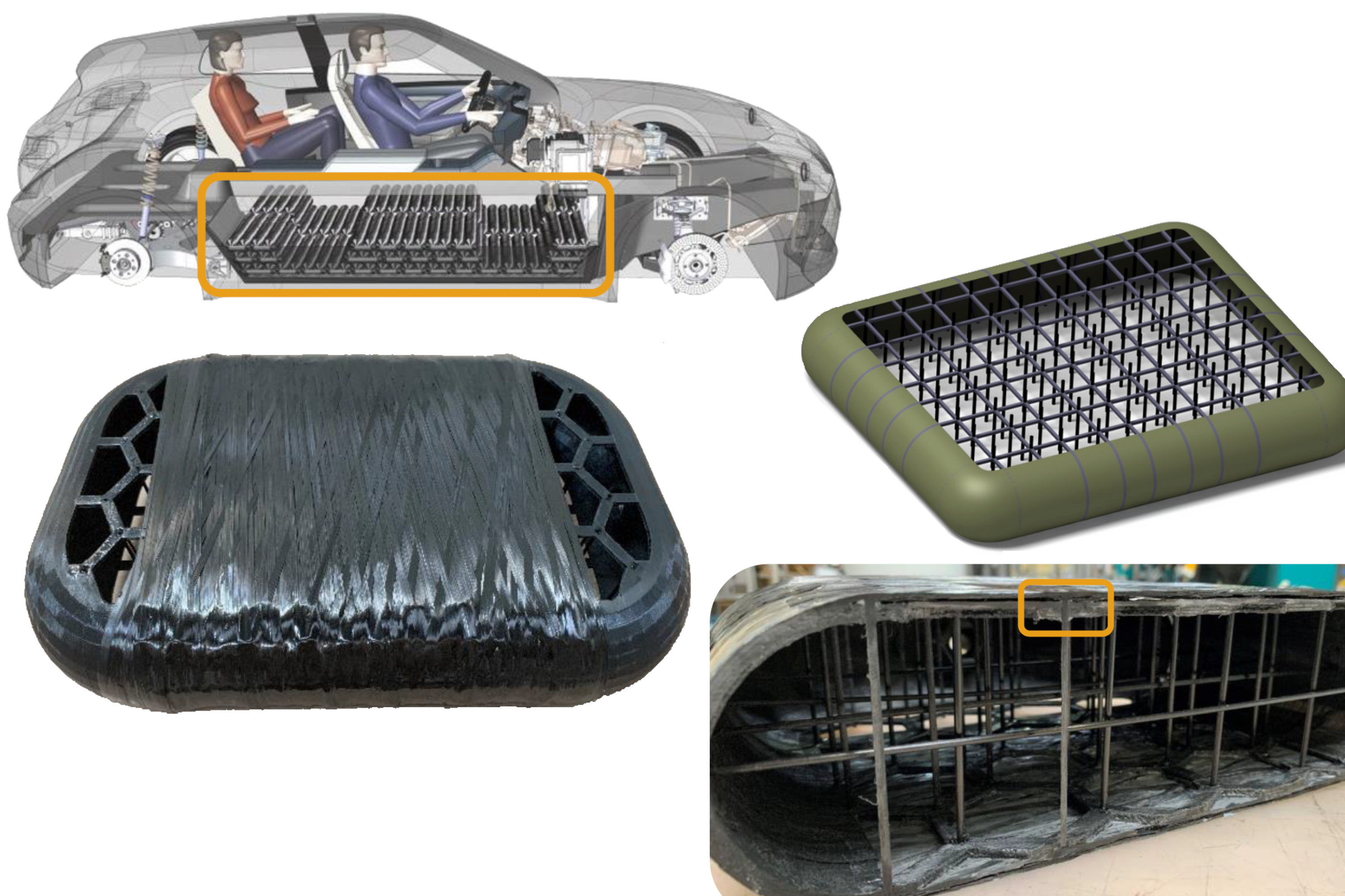
After work with BMW showed cuboidal tanks could provide higher volumetric efficiency than multiple small cylinders, TU Munich began projects to develop a composite design and manufacturing process scalable for serial production. Photo Credit: TU Dresden (upper left), Technical University of Munich, Chair of Carbon Composites (LCC)
Fuel cell electric vehicles (FCEV) powered by zero-emission hydrogen (H2) provide an additional means to reach net zero climate goals. H2-powered FC passenger cars can be refueled in 5-7 minutes for a driving range of 500 kilometers but are currently more expensive due to low production volumes. One means of cost reduction is to use one standard platform for BEV and FCEV car models. This is currently not possible because the Type 4 cylindrical tanks used to store compressed gas H2 (CGH2) at 700 bar in FCEV do not fit into the underbody battery enclosures well-developed for BEV. However, pillow-shaped, cuboidal pressure vessels could fit into that flat package space.
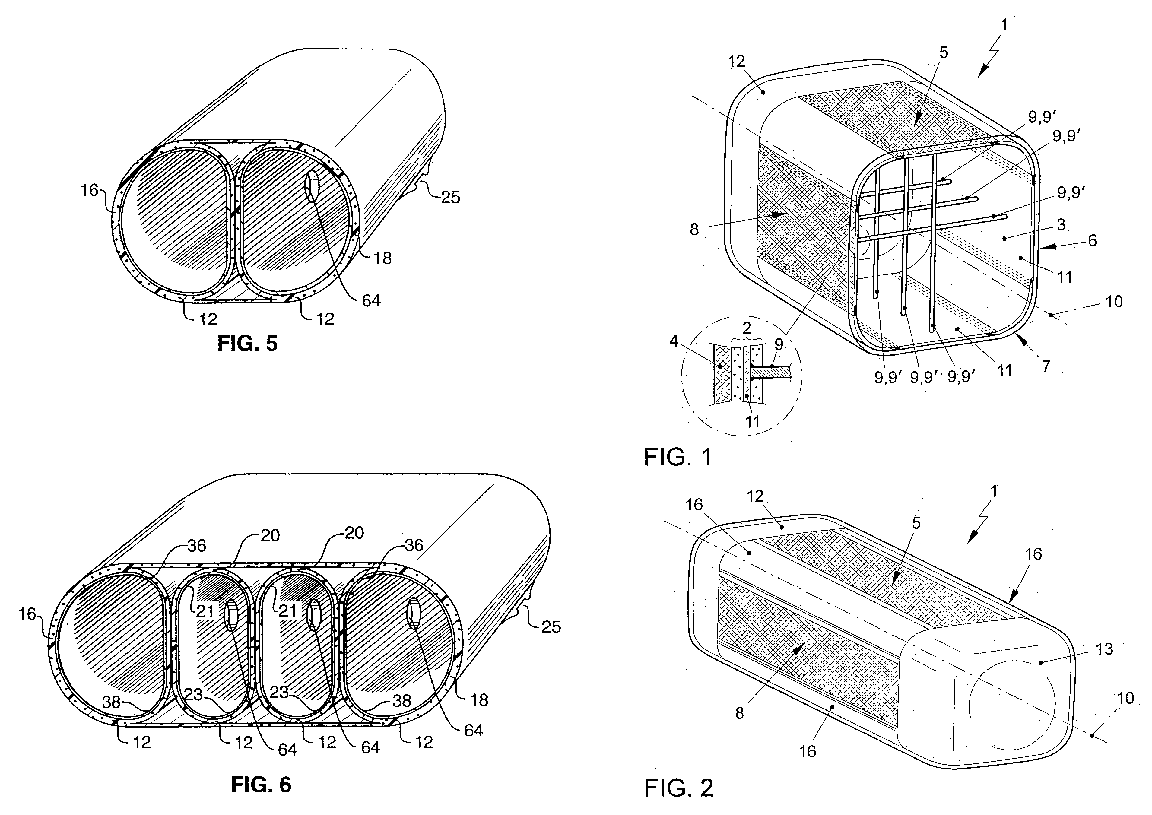
“Composite conformable pressure vessel” patent US5577630A, application filed 1995 by Thiokol Corp. (left) and rectangular pressure vessel patented by BMW in 2009 (right).
The Chair of Carbon Composites (LCC) at the Technical University of Munich (TUM, Munich, Germany) is participating in two projects developing this concept. The first is Polymers4Hydrogen (P4H), headed by the Polymer Competence Center Leoben (PCCL, Leoben, Austria). The work package at LCC is led by research associate Elisabeth Gleis.


The second project is Hydrogen Demonstrator and Development Environment (HyDDen), with the LCC work led by research associate Christian Jäger. Both aim to produce scaled demonstrators of the manufacturing process to produce a conformable CGH2 tank using carbon fiber composites.
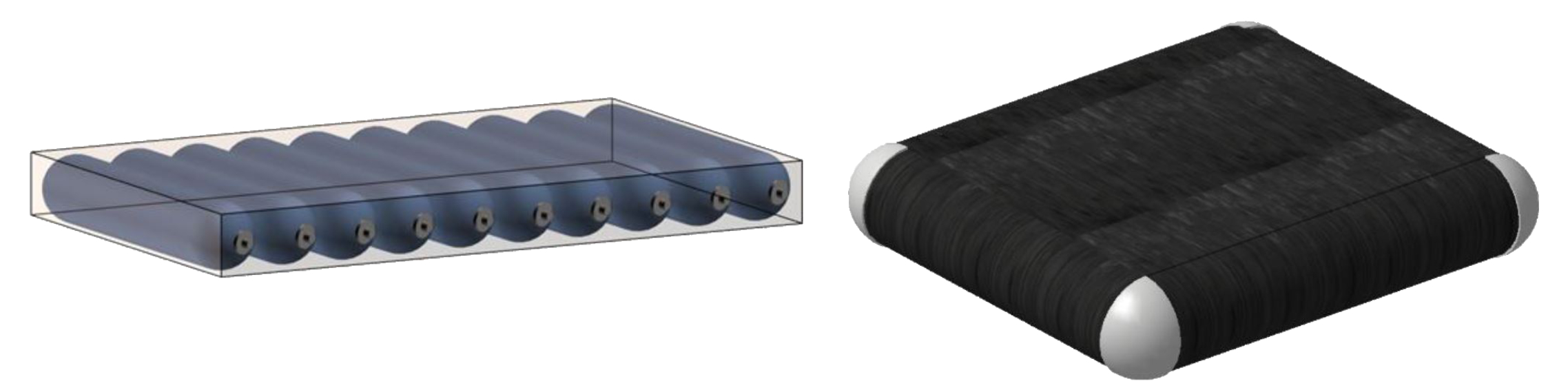
Limited volumetric efficiency in packing small-diameter cylinders into flat battery space (left) and Type 2 cuboidal pressure vessel made with a steel liner and carbon fiber/epoxy composite overwrap (right). Photo Credit: Fig. 3, 6 from “ A numerical approach to design a type II box-shaped pressure vessel with inner tension struts,” by Ruf and Zaremba, et al.
P4H has already produced a proof-of-concept cuboidal tank using a thermoplastic skeleton with composite tension straps/struts that is overwound with carbon fiber-reinforced epoxy. HyDDen will pursue a similar design but use automated fiber placement (AFP) to produce an all-thermoplastic composite tank.
Brief history of conformable tanks
Designs for conformable tanks have been studied for decades, from Thiokol Corp.’s “Composite conformable pressure vessel” patent application in 1995, to the 1997 German patent DE19749950C2 for a compressed gas container “which can have any geometric configuration,” but especially flat and irregular shapes, using support elements in the cavity connected to the cladding layer so that they take the expansion forces of the gas.
A 2006 paper by Lawrence Livermore National Laboratory (LLNL) described three approaches: a filament wound conformable pressure vessel, a microlattice pressure vessel comprising an orthogonal lattice internal structure (small cell size of 2 centimeters or less) surrounded by a thin outer skin for H2 containment, and a replicant vessel comprising an internal structure formed by bonded small components (e.g., hexagonal plastic rings) with a thin outer containment skin. Replicant vessels are most appropriate for large sizes where conventional techniques may be difficult to apply.
Volkswagen’s 2009 application for patent DE102009057170A described a pressure vessel for installation in a vehicle which would offer a high weight efficiency while enabling improved space utilization. The rectangular cross-section tank used tensile connectors between two rectangular opposing wall sections while the corners were rounded.
Design for cuboidal tank with integrated tension struts. Photo Credit: TU Munich LCC
Why use cuboidal tanks?
Gleis references the concepts above as well as other approaches in the paper “Development of a manufacturing process for a cuboidal pressure vessel with tension struts,” presented by Gleis, et al. at the ECCM20 conference (June 26-30, 2022, Lausanne, Switzerland). In that paper, she cites TUM research published by Michael Ruf and Swen Zaremba which found that a cuboidal pressure vessel with tension struts connecting the rectangular sides provided roughly 25% more storage versus multiple small cylinders packed into a flat battery space.
The problem with packing numerous small Type 4 cylinders into a flat enclosure, explains Gleis, “is that you lose a lot of volume between the cylinders and that system also has a very large surface for H2 gas permeation. Overall, this system provides less storage volume than a cuboidal tank.”
Cuboidal tank, MAI Skelett approach
However, a cuboidal tank design presents other issues. “It’s clear that you need to counteract the bending forces on the flat walls due to the pressurized gas,” says Gleis. “To do this, you need reinforcing structures on the inside that connect into the tank walls. But that's difficult to manufacture with composites.”
Gleis and her team sought to integrate reinforcing tension struts in the pressure vessel in a way that would work with the filament winding process. “That’s important for enabling high-volume production,” she explains, “and it also allows us to design the winding pattern in the vessel wall to optimize the fiber orientations per load in each area.”
Four steps in fabrication of P4H project’s proof-of-concept cuboidal composite tank. Photo Credit: “Development of a manufacturing process for a cuboidal pressure vessel with tension struts”, TU Munich, Polymers4Hydrogen project, ECCM20, June 2022.
To enable winding, the team came up with a new concept that has four basic steps shown above. The tension struts — shown in the steps as black posts — are positioned in a prefabricated skeleton structure which is made using a method drawn from the MAI Skelett project. In this project, BMW developed a “skeleton design” for a windshield frame using four fiber-reinforced pultruded bars and then overmolded these in a plastic frame.
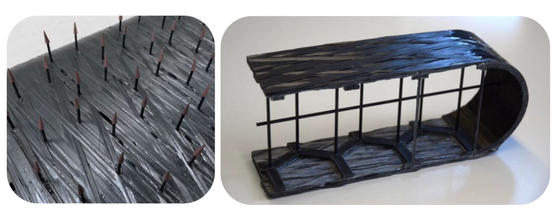
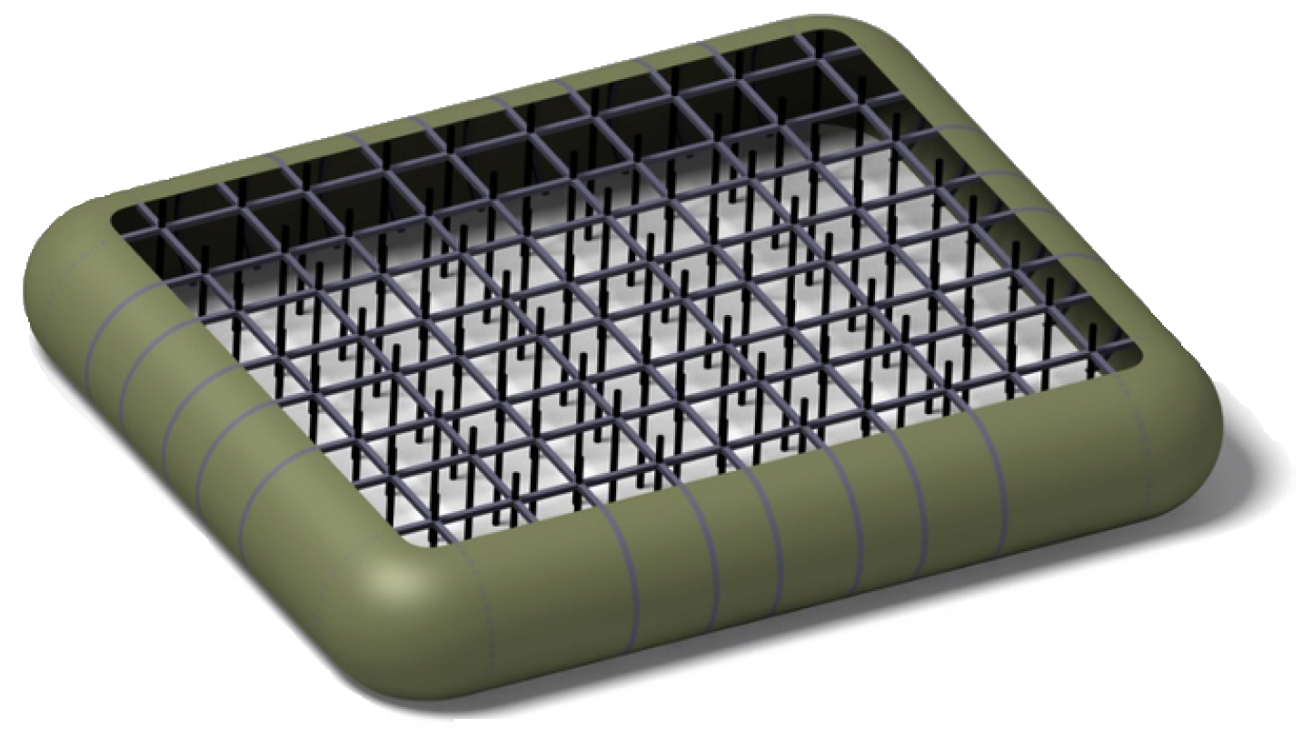
Skeleton for proof-of-concept cuboidal tank. TUM 3D printed hexagonal skeleton sections using unreinforced PLA filament (top), inserted pultruded CF/PA6 rods to serve as tension struts (middle) and then filament wound over the struts (bottom). Photo Credit: TU Munich LCC
“Our idea was that you could build a cuboidal tank skeleton as a modular structure,” says Gleis. “You then place these modules into an overmolding tool, place the tension struts into the skeleton modules and then use the MAI Skelett method to injection mold around the struts, integrating them with the skeleton sections.” This could be an efficient method for serial production, she adds, resulting in a structure that would then serve as a mandrel or core for filament winding the tank’s composite shell.
TUM designed the tank skeleton as a cuboidal “pillow” with solid sides, rounded corners and a hexagonal pattern on the top and bottom through which tension struts could be inserted and attached. The holes for these struts were also 3D printed. “For our initial proof-of-concept tank, we 3D printed the hexagonal skeleton sections using polylactic acid [PLA, a bio-derived thermoplastic] because it was easy and cheap,” says Gleis.
The team bought 68 pultruded carbon fiber-reinforced polyamide 6 (PA6) rods from SGL Carbon (Meitingen, Germany) to use as tension struts. “For this proof of concept, we did not perform any overmolding,” says Gleis, “but instead simply inserted the struts into the 3D-printed honeycomb skeleton core and bonded them using epoxy adhesive. This then provided the mandrel for filament winding the tank.” She notes that although it was relatively easy to wind around these rods, there were also significant issues, which will be described later.
“For this first step, our goal was to demonstrate the manufacturability of this design and disclose challenges in the manufacturing concept,” Gleis explains. “So, the tension struts protruded through the outer surface of the skeleton structure and we used wet filament winding to attach the carbon fibers onto that core. After this, in the third step, we bent the head of each tension strut. Because the struts were made from thermoplastic, we simply used heat to reshape the head so that it was flattened and anchored into the first layers of winding. And then we continued winding around the structure again, so that the flattened heads of the tension struts were geometrically encapsulated within the tank wall laminate.”
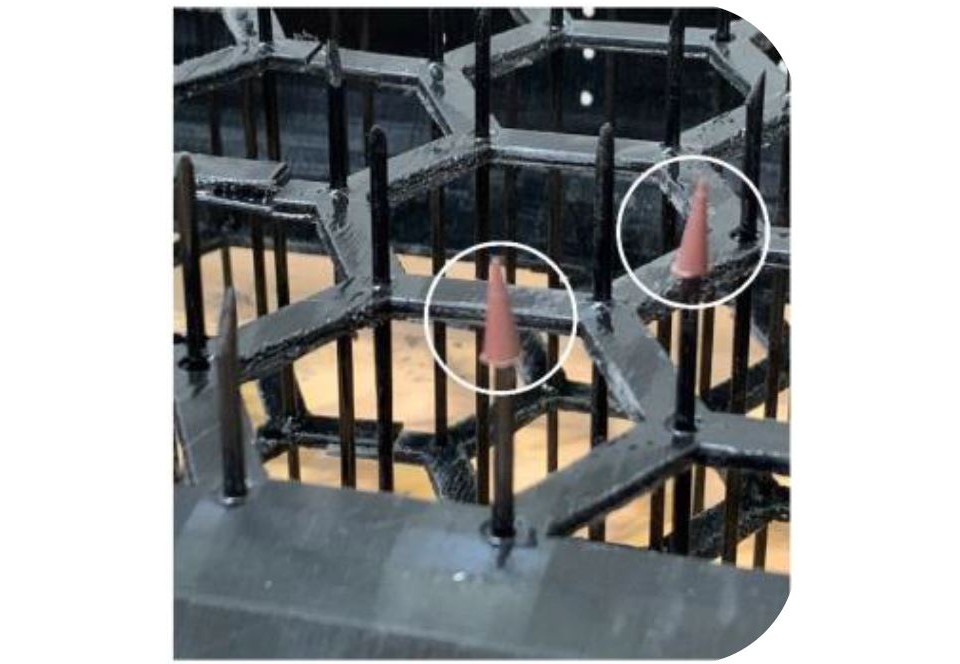
Tension strut caps for winding. TUM used plastic caps on the end of the tension rods to prevent fibers from being caught during filament winding. Photo Credit: TU Munich LCC
Cones, reshaping struts and winding
Gleis reiterates this first tank was a proof of concept. “The use of 3D printing and adhesives was just for initial validation and gave us insights on several challenges we face. For example, during filament winding, the fibers get caught on the ends of the tension struts, which leads to fiber breakage, fiber damage and decreased laminate quantity. To address this, we used some plastic caps as a manufacturing aid, placed onto the struts before the first winding steps. Then, when the inner laminate had been produced, we removed these protective caps and proceeded to reshape the strut ends before final winding.”
The team trialed different options for reshaping. “Those that appear circular worked best,” says Gleis. “Also, for the prototyping phase, we used a modified soldering tool to introduce heat and reshape the tension strut ends. In a serial production concept, you would have a larger tool that simultaneously shapes and overmolds all the strut ends into the inner wall laminate.”
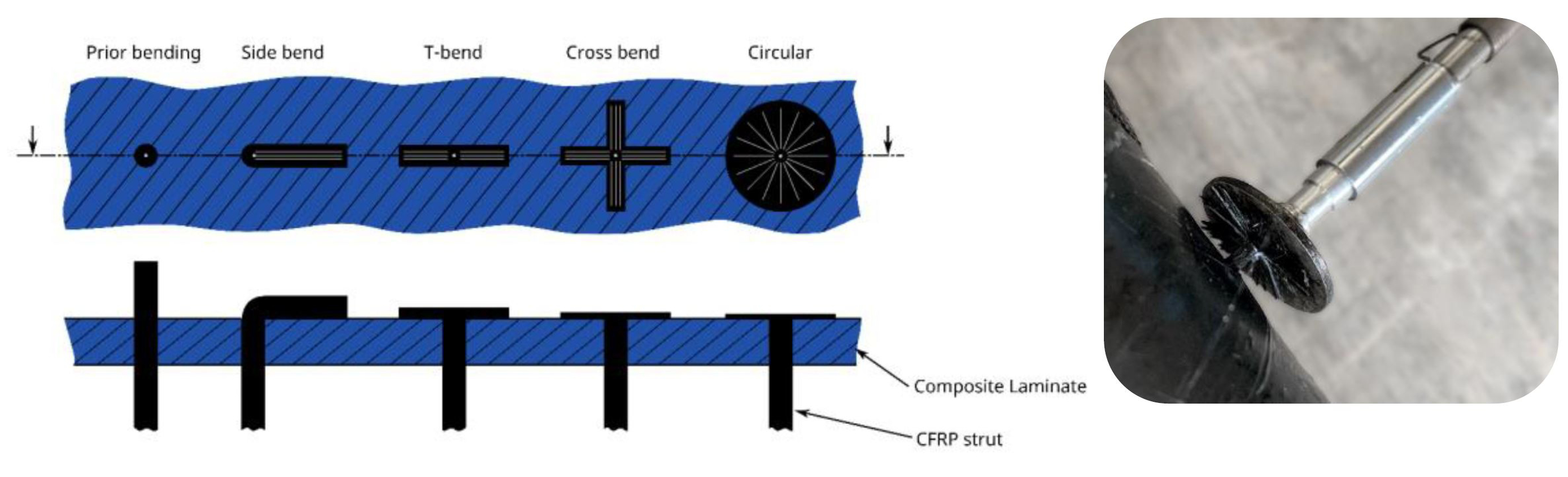
Reshaping tension strut heads. TUM trialed multiple concepts and a modified soldering head for flattening the ends of the composite tension struts to achieve anchoring in the tank wall laminate. Photo Credit: “Development of a manufacturing process for a cuboidal pressure vessel with tension struts”, TU Munich, Polymers4Hydrogen project, ECCM20, June 2022.
Thus, the laminate was cured after the first winding step, the struts were reshaped, TUM completed the second filament winding and then performed a second cure for this outer tank wall laminate. Note, this is a Type 5 tank design, meaning it has no plastic liner as a barrier for gas permeation. See discussion below in “Next Steps”.
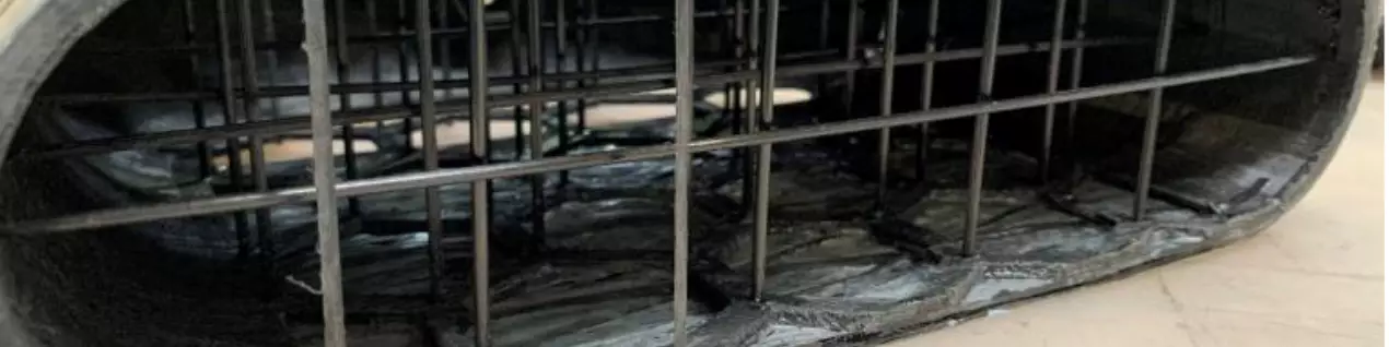
“We cut the first demonstrator into cross-sections and imaged the linkage areas,” says Gleis. “In the close-ups, you could see that we had some issues with laminate quality and the strut head did not lay flat on the inner laminate.”
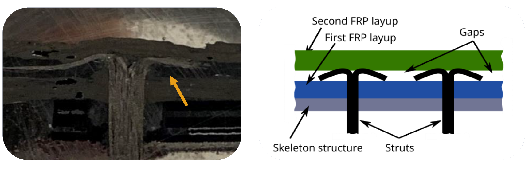
Addressing the issue of gaps between inner and outer tank wall laminate. The reshaped tension strut heads created gaps between the first and second windings in the proof-of-concept tank. Photo Credit: TU Munich LCC
This initial 450 × 290 × 80-millimeter tank was completed last summer. “Since then, we have made a lot of progress, but we still have gaps in between the inner and outer laminate,” says Gleis. “So, we tried using a high-viscosity neat resin to fill these gaps. This actually improved the connection between the struts and the laminate, and thus significantly increased the mechanical load capability.”
The team continues to develop the tank design and process, including solutions for the winding patterns required. “The proof-of-concept tank was not fully wound on the sides because it's difficult to generate winding paths for such a geometry,” explains Gleis. “Our initial windings were 75°, but we know a variety of patterns are required to meet the loads in this pressure vessel. We are still looking to solve this issue but it’s not so easy with the software that's on the market currently. This might be a follow-up project.”
How much CGH2 could such a tank store? “Our preliminary studies showed that a cuboidal tank fitting into a 1600 x 2300 x 130-millimeter space could hold 6.8 to 7.4 kilograms of hydrogen,” says Gleis. “But that depends on how many sub-divided cuboidal vessels you pack into the design space. We have not yet developed a detailed tank design, but we are aiming for 700 bar applications, as that is the standard in the automotive industry.”
Next steps
“We have proven the feasibility of this manufacturing concept,” says Gleis, “but we need to further work on improving the connection between the laminate and the reshaped tension struts. We are doing this work now and have developed a method for pull-out testing in a tensile test machine. You pull the strut out of the laminate and test the mechanical loads those connections can take.”
This part of the Polymers4Hydrogen project is set to wrap at the end of 2023, at which point Gleis hopes to have completed a second demonstrator tank. It is interesting to note the design to-date has used neat and reinforced thermoplastic in the skeleton and a thermoset composite for the tank wall. Will this hybrid approach be used in the final demonstrator tank? “Yes,” says Gleis. “Our partners in the Polymers4Hydrogen project are developing epoxies and other composite matrix materials with better hydrogen barrier properties.” She lists two partners doing that work — PCCL and the Tampere University (Tampere, Finland).
Gleis and her team are also exchanging information and brainstorming with Jäger in the second LCC conformable composite tank project within HyDDen.
HyDDen project
“We will produce a conformable composite pressure vessel for a research drone,” says Jäger. “This is a collaboration between two chairs in TUM’s Department of Aerospace and Geodesy — the LCC and the Chair of Helicopter Technology (HT). This project will finish at the end of 2024 and currently, we are close to finalizing the pressure vessel design, which is more about an aerospace versus automotive approach. After this initial concept phase, the next step is to perform a detailed structural simulation and prediction of the wall structures’ barrier properties.”
“The whole idea is to develop a research drone with a hybrid fuel cell and battery electric powertrain,” he continues. It would use batteries during the periods of high power load — namely, takeoff and landing — and then switch to the fuel cell for low-load cruise periods. “The HT team already has a research drone where they redesigned the powertrain to use both batteries and a fuel cell,” says Jäger. “And they have bought CGH2 storage tanks for testing this powertrain.”
“The task of my team is to build a prototype pressure vessel tank that is conformable, but not because a cylindrical tank creates packaging problems,” he explains. “Flatter tanks won’t have such a large wind resistance. In this way, you obtain a better flight performance.” The tank would measure roughly 830 x 350 x 173 millimeters.
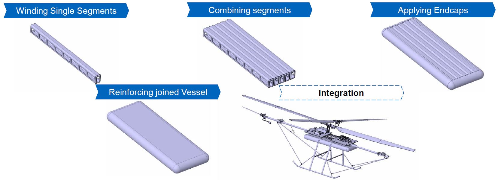
All-thermoplastic, AFP conformable tank. For the HyDDen project, the LCC team at TUM initially looked at an approach similar to that used by Gleis (top) but then transitioned to an approach using multiple structural modules combined and then overwound using AFP (bottom). Photo Credit: TU Munich LCC
“One idea was a similar approach as Elisabeth [Gleis],” says Jäger, “applying tension struts in the vessel walls to compensate for the high bending forces. However, we are not manufacturing the tank using the winding process but instead using AFP. Thus, we thought of creating single segments of the pressure vessel which will have the struts already integrated. This approach allows me to combine several of these integrated modules and then apply end caps before a final AFP winding to encapsulate everything.”
“We're trying to finalize such a concept,” he continues, “but also start testing for the materials selection, which is important for having the necessary resistance to H2 gas permeation. We’re working mainly with thermoplastic materials for this, and we’re looking at how different materials will influence this permeation behavior as well as the processing in the AFP machine. It’s important to understand if the processing will be an influence and if any post-processing is needed. We also want to know if different layups influence the permeation of hydrogen through the pressure vessel.”
This tank will be completely thermoplastic, with tape materials supplied by Teijin Carbon Europe GmbH (Wuppertal, Germany). “We will work with their PPS [polyphenylene sulfide], PEEK [polyetheretherketone] and LM PAEK [low-melt polyarylketone] materials,” says Jäger. “And then it's about comparing to see which of these is best for resistance to permeability and for producing parts with the best properties.” He hopes to complete testing, structural and process simulations and the first demonstrators completed within the next year.
Acknowledgement
This research work was performed within the COMET-module “Polymers4Hydrogen” (I.D. 21647053) in the framework of the COMET-program of the Federal Ministry for Climate Action, Environment, Energy, Mobility, Innovation and Technology and the Federal Ministry for Digital and Economic Affairs. The authors thank the involved partners Polymer Competence Center Leoben GmbH (PCCL, Austria), Montanuniversitaet Leoben (Department Polymer Engineering and Science, Chair of Chemistry of Polymeric Materials, Chair of Materials Science and Testing of Polymers), Tampere University (Department of Engineering Material Science), Peak Technology and Faurecia for their contributions to this research work. The COMET-Modul is funded by the Austrian Government and the State Governments of Styria.


.jpg;maxWidth=300;quality=90;format=webp)


Related Content

3D-printed CFRP tools for serial production of composite landing flaps
GKN Aerospace Munich and CEAD develop printed tooling with short and continuous fiber that reduces cost and increases sustainability for composites production.
Read More
The next evolution in AFP
Automated fiber placement develops into more compact, flexible, modular and digitized systems with multi-material and process capabilities.
Read More
Large-format 3D printing enables toolless, rapid production for AUVs
Dive Technologies started by 3D printing prototypes of its composite autonomous underwater vehicles, but AM became the solution for customizable, toolless production.
Read More
Sulapac introduces Sulapac Flow 1.7 to replace PLA, ABS and PP in FDM, FGF
Available as filament and granules for extrusion, new wood composite matches properties yet is compostable, eliminates microplastics and reduces carbon footprint.
Read MoreRead Next

From the CW Archives: The tale of the thermoplastic cryotank
In 2006, guest columnist Bob Hartunian related the story of his efforts two decades prior, while at McDonnell Douglas, to develop a thermoplastic composite crytank for hydrogen storage. He learned a lot of lessons.
Read More
Composites end markets: Energy (2024)
Composites are used widely in oil/gas, wind and other renewable energy applications. Despite market challenges, growth potential and innovation for composites continue.
Read More
CW’s 2024 Top Shops survey offers new approach to benchmarking
Respondents that complete the survey by April 30, 2024, have the chance to be recognized as an honoree.
Read More