


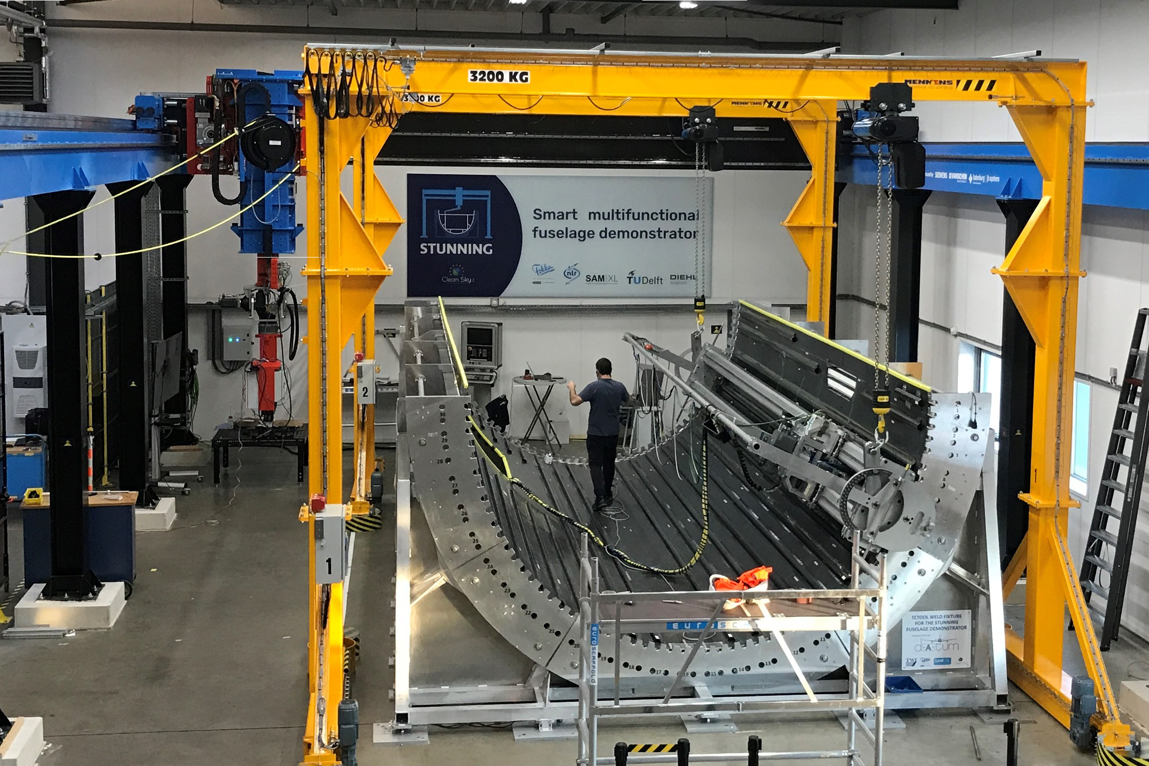
Welded stringers in lower half of MFFD
GKN Fokker conduction welds CF/LMPAEK stringers to the skin of the Multifunctional Fuselage Demonstrator (MFFD) lower half being assembled at SAM|XL as part of Clean Sky 2’s STUNNING project. Photo Credit: GKN Fokker, SAM|XL
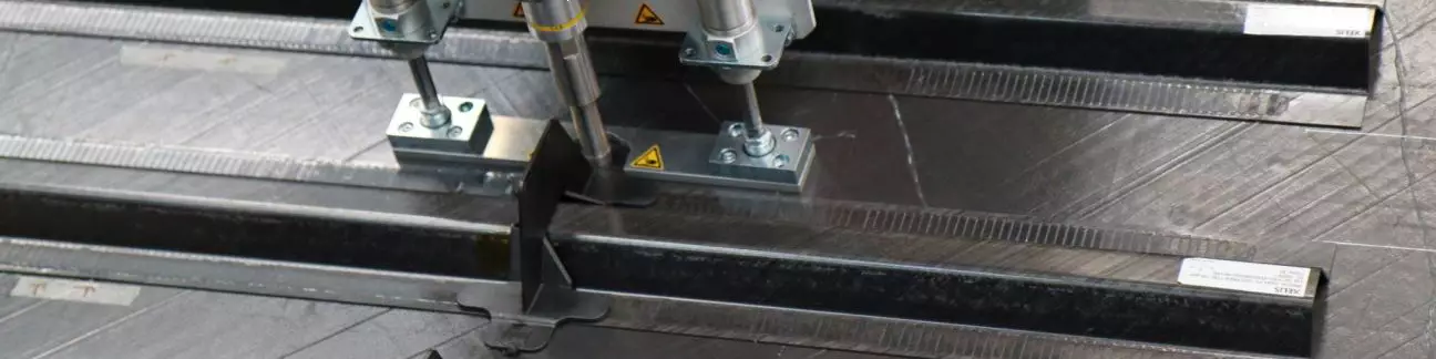
Landscape photo at top: Clips being ultrasonically welded to stringers and fuselage skin for the MFFD lower half being assembled at SAM|XL. Photo Credit: SAM|XL
Thermoplastic composites welding has the potential to significantly improve the sustainability of commercial aircraft production. Tier 1 airframer Collins Aerospace (Charlotte, N.C., U.S.) claims on its website that more automated, out-of-autoclave (OOA), weldable thermoplastic structures have the potential to reduce manufacturing cycle time by up to 80% and weight by up to 50% compared to previous metal and thermoset composite assemblies. These previous assemblies use drilling and mechanical fasteners, requiring up to nine manufacturing steps. “We believe that for a new, A320-type single-aisle aircraft in five to eight years, thermoplastic composites will be a game-changer, not only to enable higher production rates but also best cost and weight,” says Cedric Eloy, deputy chief CTO, Tier 1 airframer Daher Aerospace (Paris, France).
“If we want to take advantage of thermoplastic composites, we need to weld for fastener-less assembly, or at least with minimal fasteners,” adds Dominique Bailly, Daher VP of R&D.


Thermoplastic composite structures have been certified and flying for decades. These include resistance-welded main landing gear doors on the Fokker 50 in 1998, j-nose leading edge wing structures on the Airbus A340 and A380 in 2000 and 2006, respectively and induction-welded carbon fiber (CF)/polyphenylene sulfide (PPS) elevators and rudder on the Gulfstream G650 business jet in 2008. “There are more than 500 G650 aircraft flying,” notes Arnt Offringa, director of the GKN Aerospace (Solihull, U.K.) Global Technology Centre Netherlands (GTC-NL, Hoogeveen). “Gulfstream now has seven aircraft models using welded thermoplastic control surfaces, and we are continuing production, so it’s become an established manufacturing method.” Offringa was a key champion in the induction-welded structures listed above, which were developed and produced by Fokker Aerostructures (Hoogeveen), now part of Tier 1 airframer GKN Aerospace. For these structures, GKN Fokker uses KVE Composites’ (The Hague, Netherlands) patented induction welding process. Induction, conduction and resistance welding are all defined and discussed in CW’s 2018 feature article on thermoplastic composites welding.
There have been numerous welding developments since 2018 (see “Composites welding developments” sidebar below), including a move toward low-melt polyaryletherketone (LMPAEK)-based composites for potential lower temperature processing versus polyetherketoneketone (PEKK) and polyetheretherketone (PEEK), continued advancements in automation and simulation and an increase in the size and complexity of demonstrators. Welding has also become more common. Most Tier 1 airframers have significant welding R&D or established capabilities, many with technology readiness levels (TRL) approaching 5-6. And even though welded structures have been certified since 1998, there is debate in the U.S. that certification of future welded structures should follow what’s been established for bonded structures. This is likely because welding in the U.S. is not as mature as it is in Europe and details of previous certifications are not widely known. In any case, a good thermoplastic composite weld should show homogeneous material through the thickness with no identifiable interface. In this way, welded structures are not at all like bonded structures.
In Europe, emphasis is on advancing process control and nondestructive testing (NDT) already used during production of certified structures, on demonstrating multiple welding techniques via fabrication and testing of ever larger demonstrators and on having the first welded structures made with unidirectional (UD) tapes — versus the previous parts made with fabric — certified and flying by 2026.
Composites welding developments
|
2019 — Clean Sky 2 Multifunctional Fuselage Demonstrator (MFFD) program switched its baseline UD CF tape material from Toray Advanced Composites Cetex TC1320 with PEKK to TC1225 with Victrex (Lancashire, U.K.) LMPAEK which potentially offers a lower melt temperature plus faster processing and lower cost. |
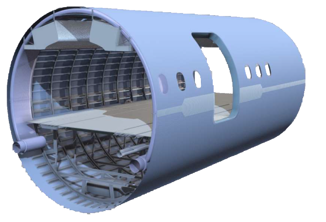 Photo Credit: |
||
|
2019 — Clean Sky 2 STUNNING project led by GKN Fokker to fabricate the MFFD lower fuselage half launched the MECATESTERS subprogram (30 months), in which KVE Composites and Rescoll (Pessac, France) will basically qualify CF/LMPAEK unitape. |
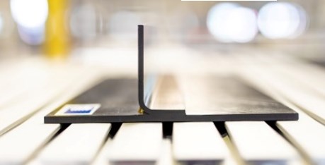 Photo Credit: |
||
|
2019 — Induction-welded ruddervators supplied by GKN Aerospace were tested as V-tail control surfaces on the Bell V-280 Valor tiltrotor. |
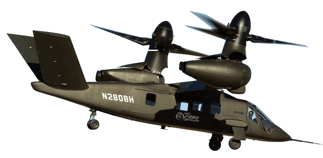 Photo Credit: Bell |
||
|
2019 — Clean Sky 2 KEELBEMAN project concluded with a 0.25- x 0.5- x 1-meter-long keel beam section demonstrator including stringers for an A320-type aircraft, made by CETMA from CF/PEKK tape using its patented induction welding process. |
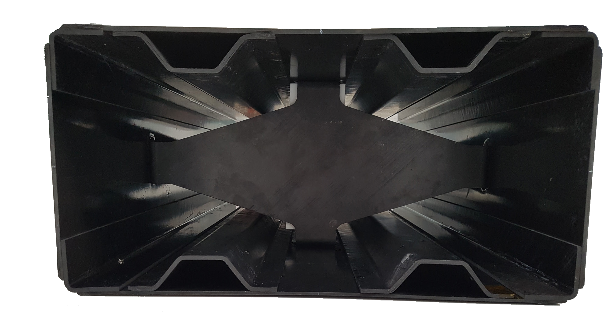 Photo Credit: |
||
|
2020 — Clean Sky 2 launched DEWTECOMP project with Tier 1 airframer Aernnova Aerospace and CETMA to develop an automated induction welding system for an integrated door surround structure (DSS) with gussets, wedges and fittings using CF/LMPAEK for the lower half of the MFFD. |
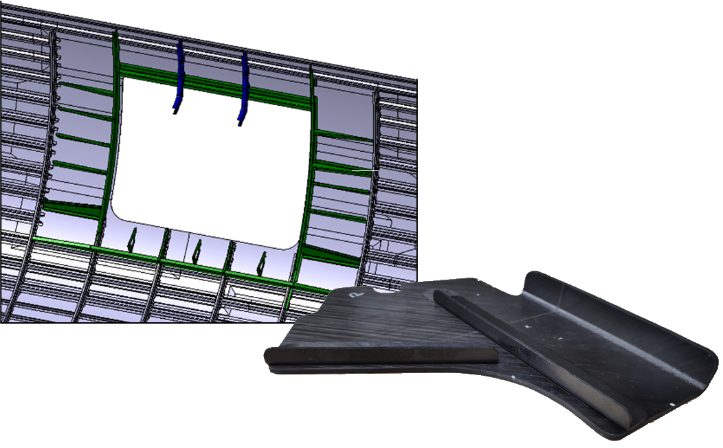 Photo Credit: DEWTECOMP |
||
|
2021 — As part of the “LuFoV-3 TB-Rumpf” project, the German Aerospace Center (DLR) Institute of Structures and Design (Stuttgart) and Airbus demonstrated an integrated fuselage intersection comprising an OOA vacuum-consolidated skin/stringer curved panel with resistance-welded frames and cleats, all made using CF/PAEK UD tape (see video). |
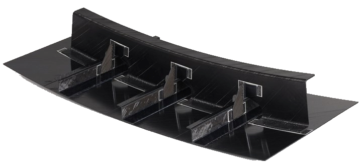 Photo Credit: DLR CC BY-NC-ND 3.0 |
||
|
2021 — Airbus Atlantic (includes Nantes, Montoir de Bretagne and previous STELIA sites) demonstrated 6-square-meter thermoplastic composite fuselage section with induction-welded stringers using IS Groupe’s and Arkema’s patented ISW process in the CORAC-funded ECHOS project. |
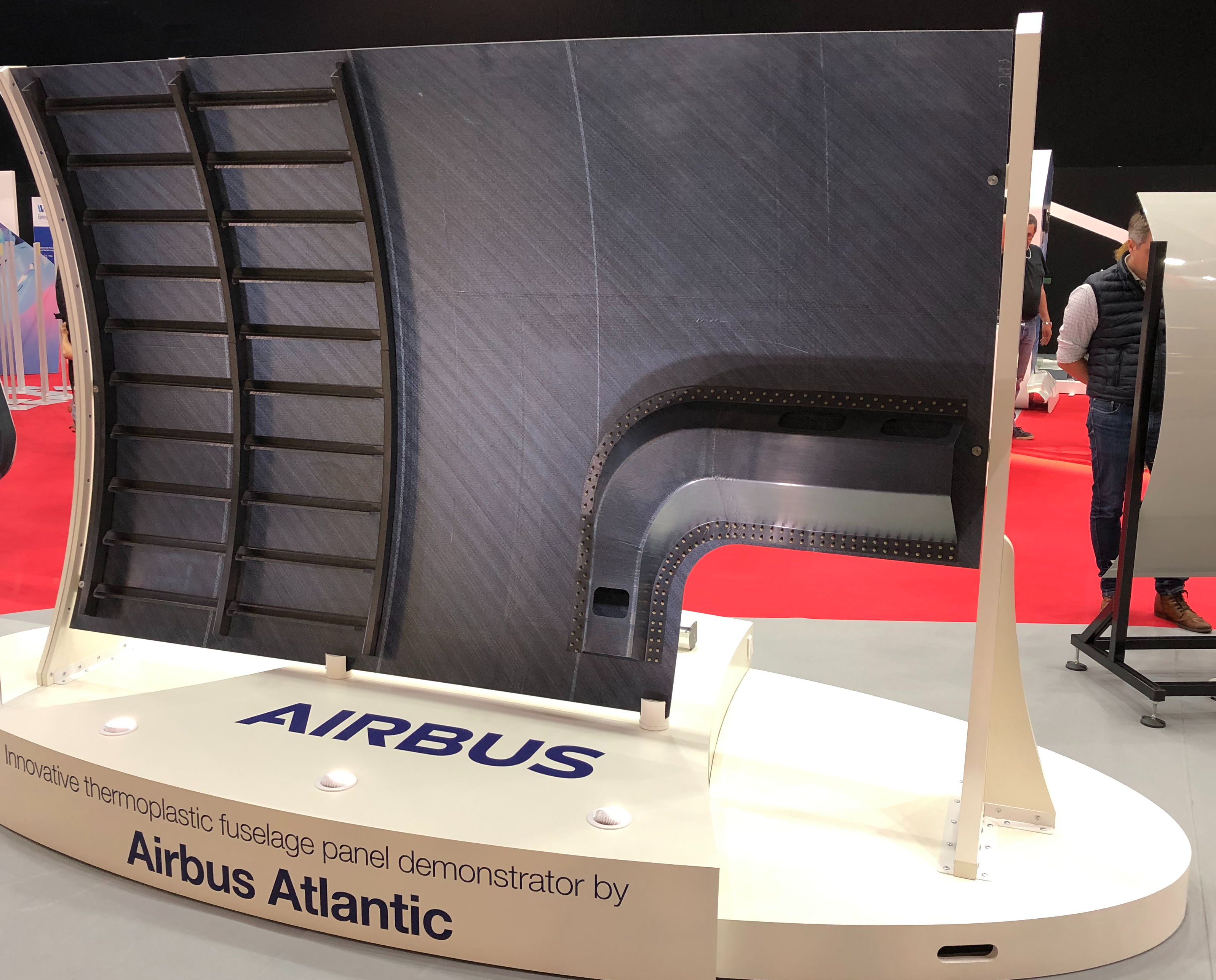 Photo Credit: IS Groupe
|
||
|
2021 — Qarbon Aerospace (Red Oak, Texas, U.S.) used a patented, susceptor-less induction welding process for its wing box demonstrator at CAMX 2021, with SLS strengths of 45-47 MPa — reportedly 30-40% higher than industry standard co-cured joints with mechanical fasteners — and weld speed of ≈0.75 meter/minute. |
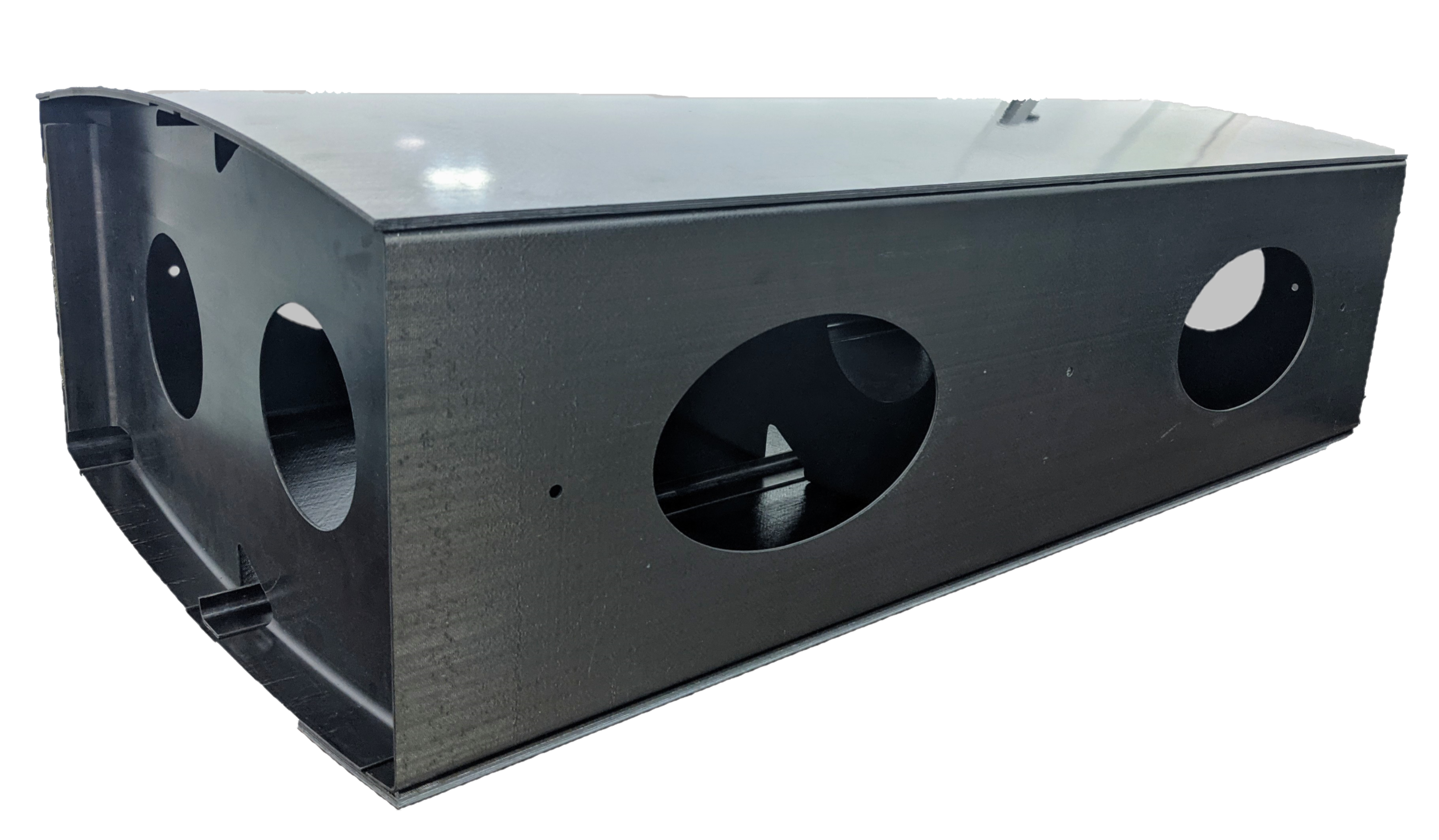 Photo Credit: Qarbon Aerospace |
||
|
2022 — KVE Composites and Daher demonstrated a 600- x 600-millimeter, curved torsion box with tapered-ply skins featuring seven welds (red) using KVE’s patented induction welding process. KVE has demonstrated 4-meter-long welds of up to 15-millimeter-thick laminates, SLS strength of 30-48 MPa and speed of one meter/minute for fabric CF/PPS and 0.20 meter/minute for UD CF/PAEK. |
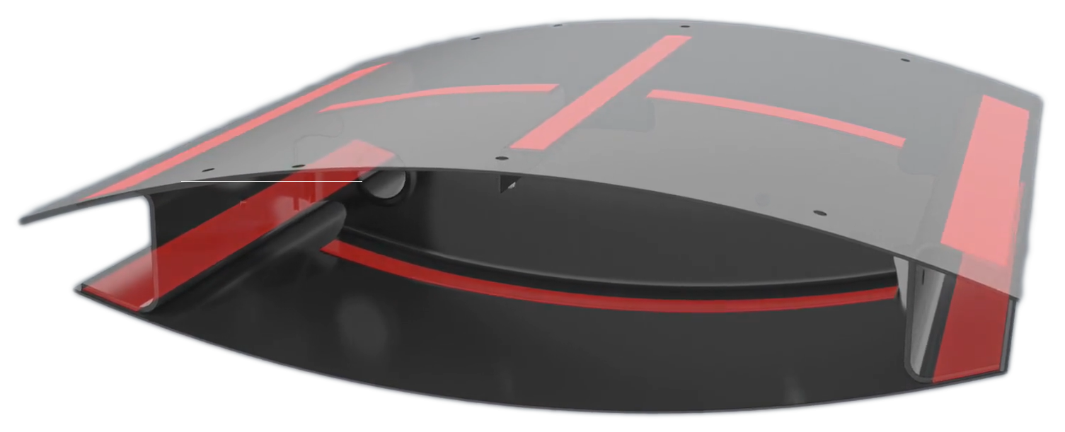 Photo Credit: |
||
|
|
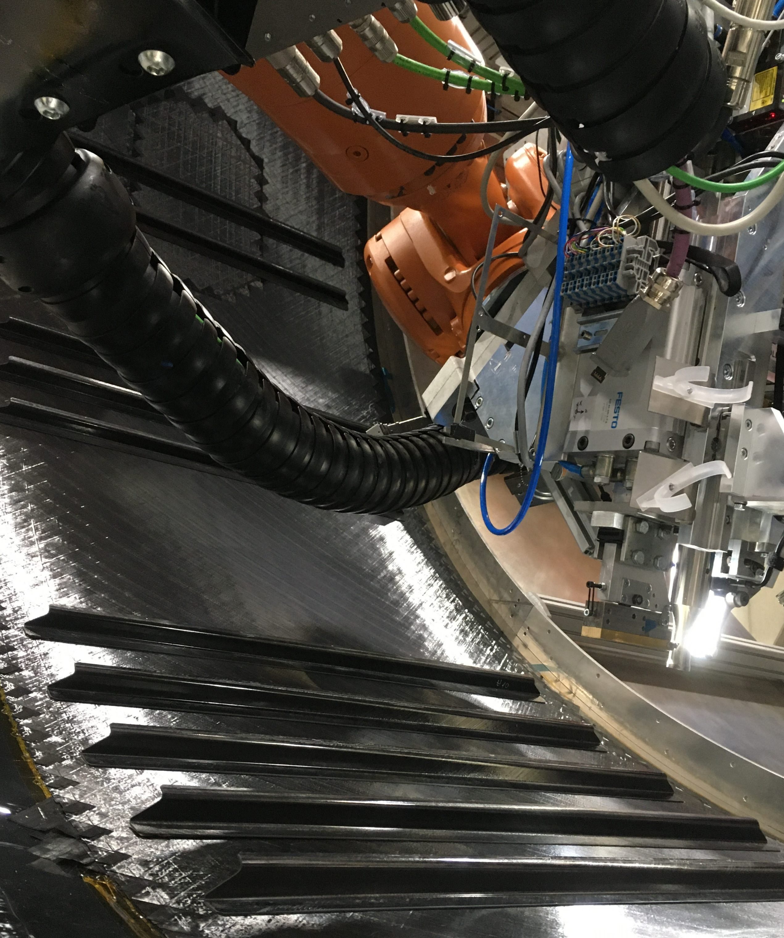 Photo Credit: DLR CC BY-NC-ND 3.0 |
||
MFFD lower half
The most significant thermoplastic composites welding project in progress is the Airbus-led Multifunctional Fuselage Demonstrator (MFFD), funded by Clean Sky 2 (now Clean Aviation). At 4 meters in diameter and 8 meters long, this A320-type fuselage section will be the world’s largest thermoplastic composites structure, once the upper and lower halves are welded together. This assembly will be completed by Fraunhofer IFAM (Stade, Germany) before the assembled barrel is delivered to Airbus (Hamburg, Germany) in 2023.
Production of the lower half is led by GKN Fokker in the STUNNING project, while the upper half is managed by the DLR Center for Lightweight Production Technology (ZLP), which is part of the DLR Institute of Structure and Design in Augsburg, Germany. Components for both halves have been made using Toray Advanced Composites (Nijverdal, Netherlands) TC1225 CF/LMPAEK unitape. As explained in a CW 2020 update, the MFFD project began in 2014 and aims to enable production of 70-100 fuselage shipsets per month, reduce fuselage weight by 10% (1,000 kilograms) and reduce fuselage costs by 20% (€1 million).
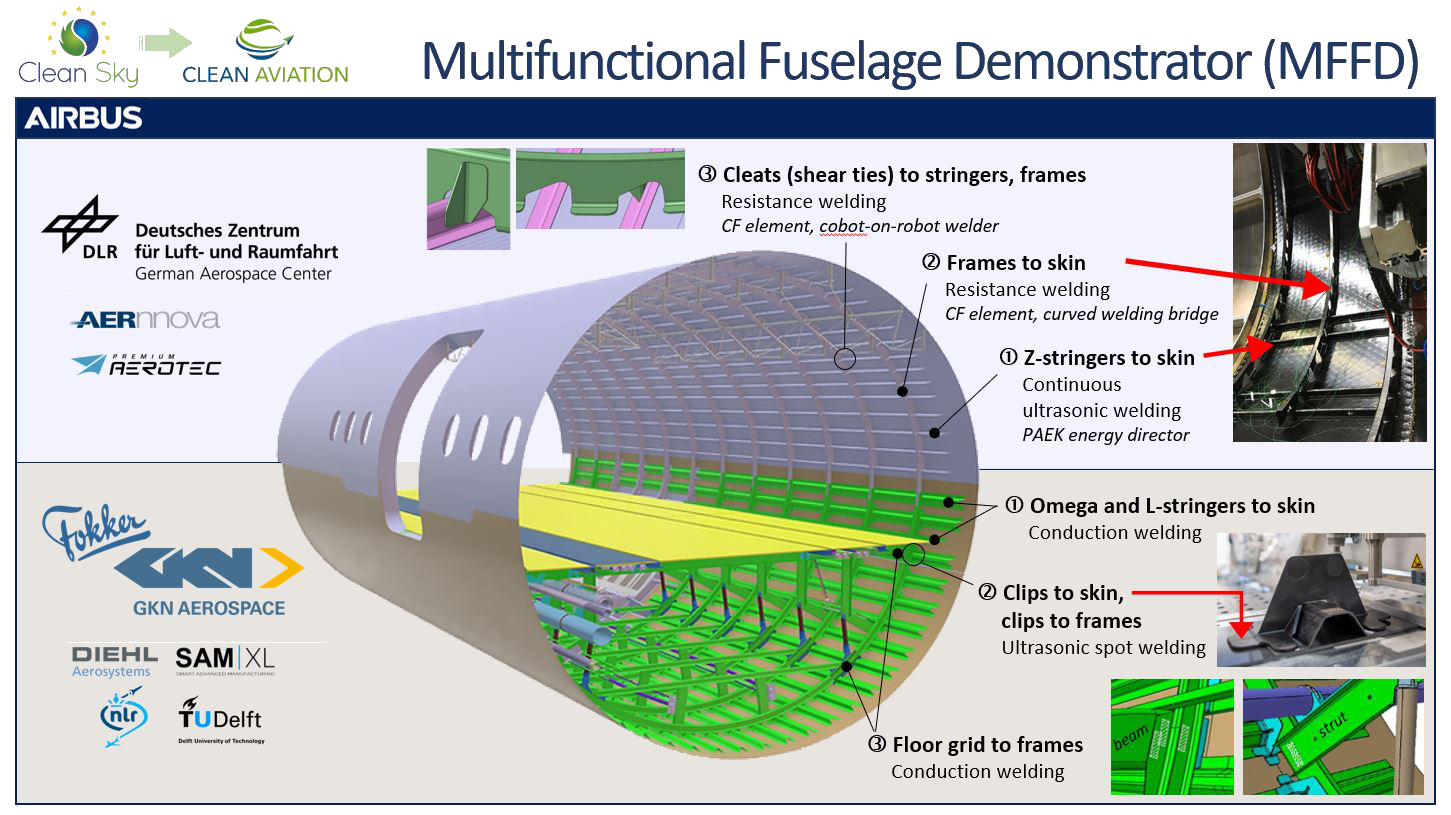
Fig. 1. Multiple welding technologies demonstrated
The welding steps for fabricating the upper and lower halves of the 4- x 8-meter-long MFFD fuselage are shown here, along with project leaders and partners. Lower half welds of floor grid to frames are shown as white hatched rectangles at lower right. Completed halves will be shipped to Airbus Hamburg by Q4 2022 to be welded together in 2023. Photo Credit: Clean Aviation, DLR, GKN Aerospace, SAM|XL
The lower half is being assembled at SAM|XL (Delft, Netherlands) with planned delivery to Airbus by the end of October 2022. The SAM|XL facility has multiple robotic arms and one large gantry-based robot for welding. As described in Fig. 1, the first step was to position and conduction weld omega stringers onto the curved fuselage skin (see CW’s 2021 blog and the SAM|XL website for more information). “The gantry robot end effector is equipped with suction cups to precisely place the stringers onto the skin,” says Kjelt van Rijswijk, CEO of SAM|XL. “It is also equipped with an ultrasonic spot welder to tack the stringers in place.”
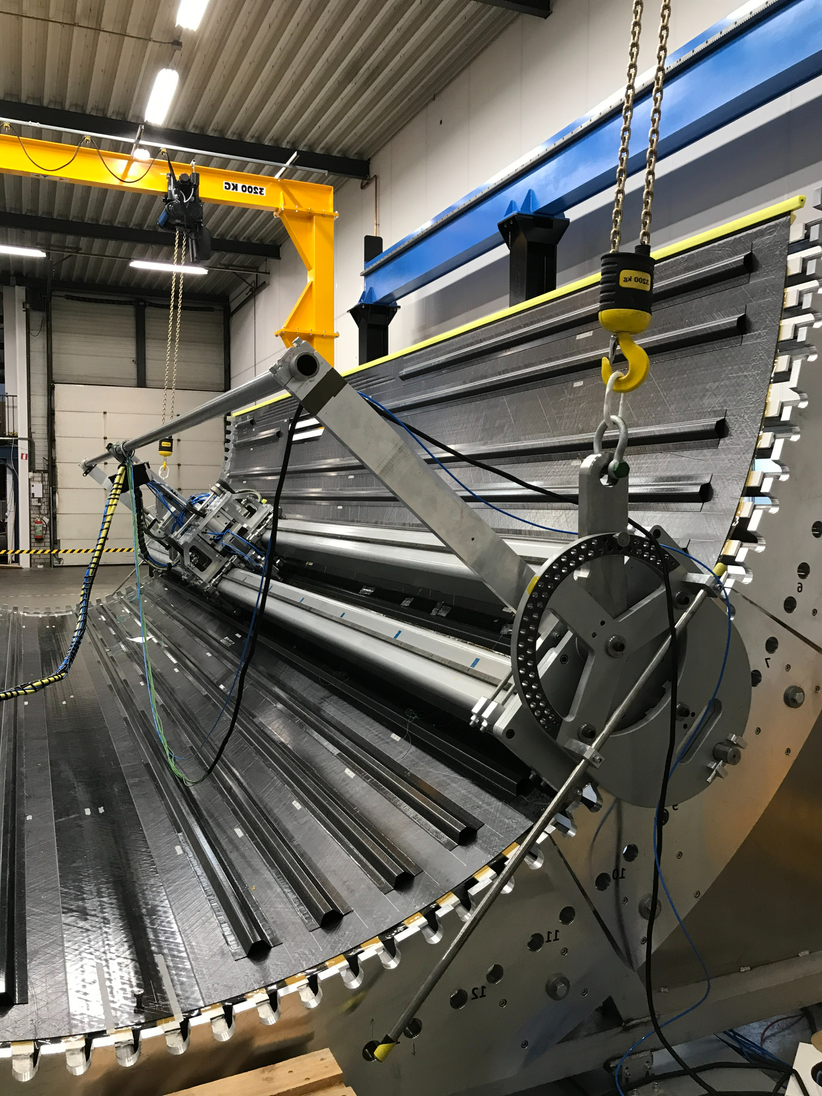
The 2.5-ton, induction heated, 1-meter-long conduction welding tool is housed within a rack and pinion-equipped hoisting fixture that positions the welder over each stringer using the notches in the circumference of the fuselage shell tool. Photo Credit: GKN Fokker, SAM|XL
GKN Fokker then welded the stringers with a 1-meter-long conduction welding tool. The metal tool is induction heated and this immediate, even heating is conducted through the stringer’s foot laminate to melt the matrix at the stringer-skin weld interface. “The tool includes a heat sink that controls temperature on the stringer surface,” explains Leo Muijs, chief technologist at GKN Fokker. “It applies pressure and then completes the welding cycle.” He notes that these omega stringers have a foot to be welded on both sides. The weld tool moves down one side, one meter at a time, with a slight overlap of 1-2 centimeters, and then completes the second side. Two L-stringers were also welded to receive the cabin floor (Fig. 1).
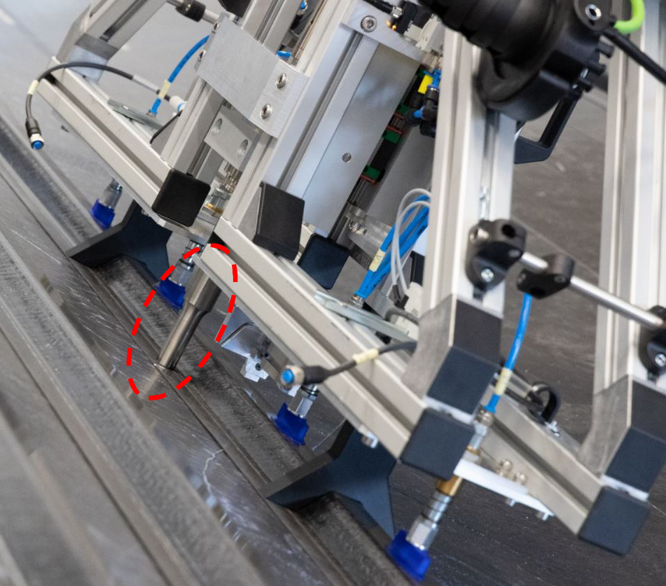
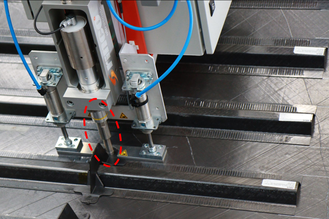
Fig. 2. Welded stringers and clips in STUNNING
The gantry robot at SAM|XL uses an end effector with suction cups and a sonotrode (dashed red circle, left) to precisely place omega stringers and tack weld them to the skin. After the stringers are conduction welded onto the fuselage skin, a second ultrasonic welding tool is used to join the clips to it. Photo Credit: SAM|XL
“Next, clips will be placed over these stringers and joined to the stringers and skin using spot ultrasonic welding,” says Van Rijswijk. Although the dedicated ultrasonic welder used for this operation has the same type of sonotrode as the tack welder (Fig. 2), it is configured differently for this high-strength weld versus tack welding. Later on, frames will be connected into the fuselage through these clips using the same ultrasonic spot-welding technique, says Bram Jongbloed, materials and process engineer at SAM|XL. “To make joints perpendicular to the skin, we have a second welder turned at 90 degrees,” he adds. This welder will press and weld the flat web of the frames to the omega-shaped flat plate of the clips (Fig. 2). Jongbloed notes that all of the ultrasonic welders were first tested on KUKA (Augsburg, Germany) robot arms to ensure they met requirements and to define the process, then moved onto the gantry robot.
“We have about 250 clips to join with ultrasonic welding, and then the frames,” says Muijs. “After that, we will install the floor grid, equipped with composite floor beams, metal seat rails and other systems. We will conduction weld where the floor beams meet the frames and also below, where the support struts meet the frames [see Fig. 1 diagram above and photos in Part 2].”
He notes lessons already learned with conduction welding in STUNNING: “Welding the stringers took much longer than we expected and also resulted in some shape changes in the skin. This is not something we have seen in previous conduction-welded demonstrators. So, we are studying that now. There are also some joggles [changes in thickness] in the stringers that we cannot go over well. The flat welding tool can deal with a certain slope, for example a 1:100 ply dropoff [e.g., one 0.14-millimeter-thick ply dropped every 14 millimeters] causes no problems, but we cannot weld a dropoff of 1:20.” There is also an issue of length. “Our smallest welding tool is roughly half a meter long, which is too long to weld a 40-centimeter stiffener, for example,” he says. But aren’t there other welding methods that could be used for these short stringers? “Yes, but they were not specified for this demonstrator, which is our current task,” says Muijs. “So, now we document these issues and include it in our final report to Airbus. When we make future designs, we can create guidelines for conduction welding that help, and we are already working on different end effectors to solve these issues. The whole goal of this demonstrator is to find these challenges and advance the technology to address them.”
MFFD upper half
DLR expects to deliver the upper half of the MFFD in early 2023. It too has amassed lessons learned, starting in July 2021 with production of a 1-meter-long, full-scale test shell to verify its technology bricks. As described in a 2021 CW blog, Fig. 2 and a DLR webpage, these include continuous and spot ultrasonic welding and resistance welding. “We used continuous ultrasonic welding for the Z-stringers and resistance welding for the frames,” explains Frederic Fischer, technical lead for thermoplastic composites production at the ZLP. “We had six frames for this test shell. We welded the first three and then went into a lessons-learned session and did a bit of rebuilding and redesign of the welding bridge. And then we finished the last three. This test shell allowed us to test the process parameters and setup of the welding elements, study the results and finalize what we are using for the final 8-meter MFFD upper shell.”
What had to be changed? “With the continuous ultrasonic welding, one of the major lessons we learned is to avoid ply endings or runouts beneath the stringer feet,” says Fischer. “These ply drops within the skin affect the weld quality.”
Michael Kupke, vice director, Institute of Structures and Design and head of department at ZLP, explains: “In continuous ultrasonic welding, heat is generated when there is damping of the ultrasonic waves. Stiffer materials transmit the waves, while softer materials increase damping. A soft layer of unreinforced polymer — the same matrix as in the composite surfaces being welded — is placed at the weld interface to control the energy during welding. This is called an energy director.” So, just as the amount of fiber changes stiffness and damping, which affects the weld, so do changes in laminate thickness. “We have to understand the effect of such changes in the surfaces being welded and address this in the process,” says Kupke.
“We will have different sets of parameters for thicker skins and thinner skins,” adds Fischer. “And this is the case also for joggles in stringers to match buildups and dropoffs in the fuselage skin. We’re adapting the welding process parameters to the layup and geometry of the parts being welded. We verified that we can weld stringers to shallow ramps with a 1:200 ratio.”
Another lesson was learned during resistance welding of the frames. “We saw that the in-situ consolidated tape skin had a comparatively high electrical conductivity. To rule out leakage currents through the fuselage skin during welding — which becomes more likely if the weld faces have similar fiber orientation — we added an insulating layer to the carbon fiber-based welding elements.”
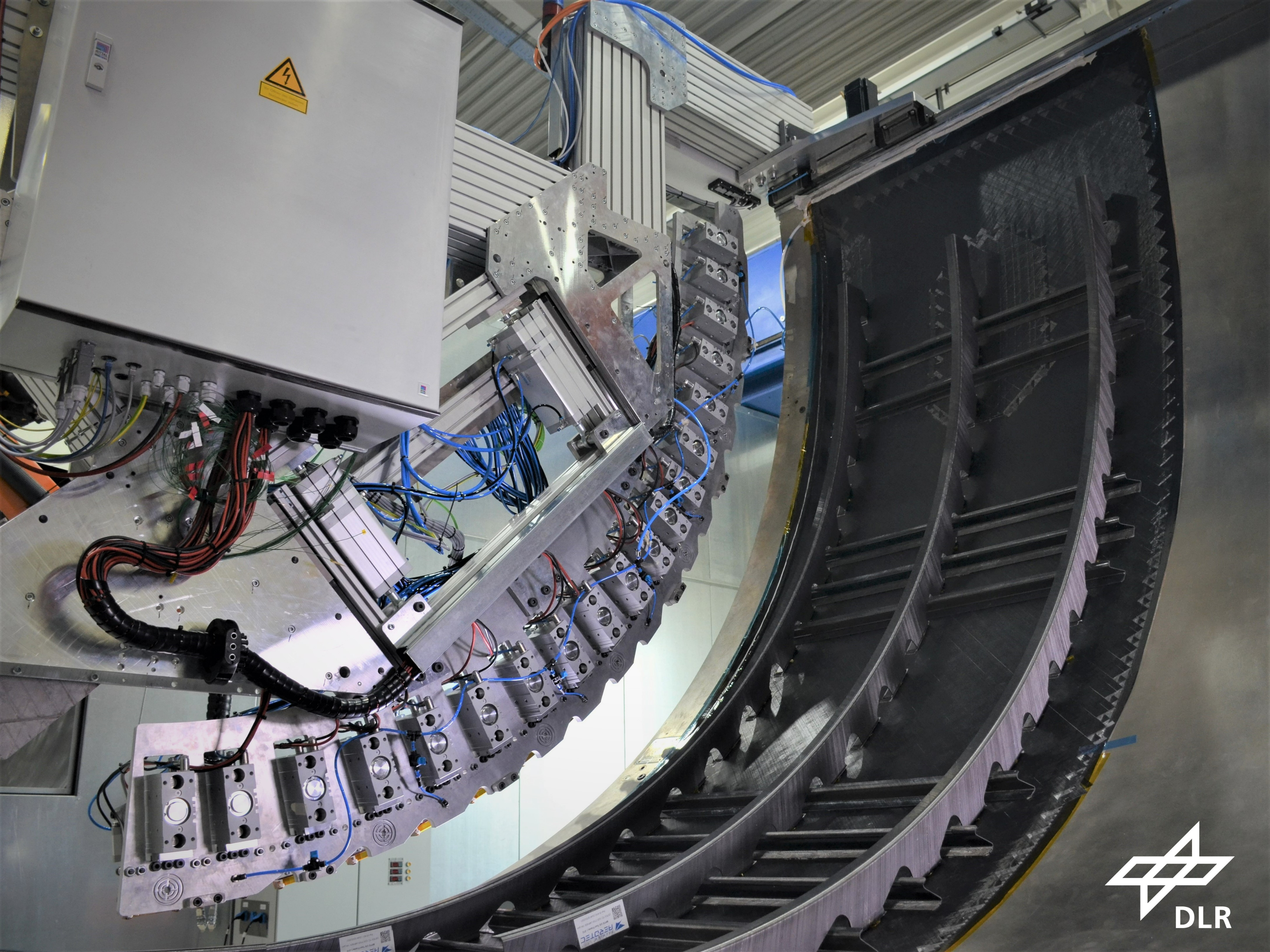
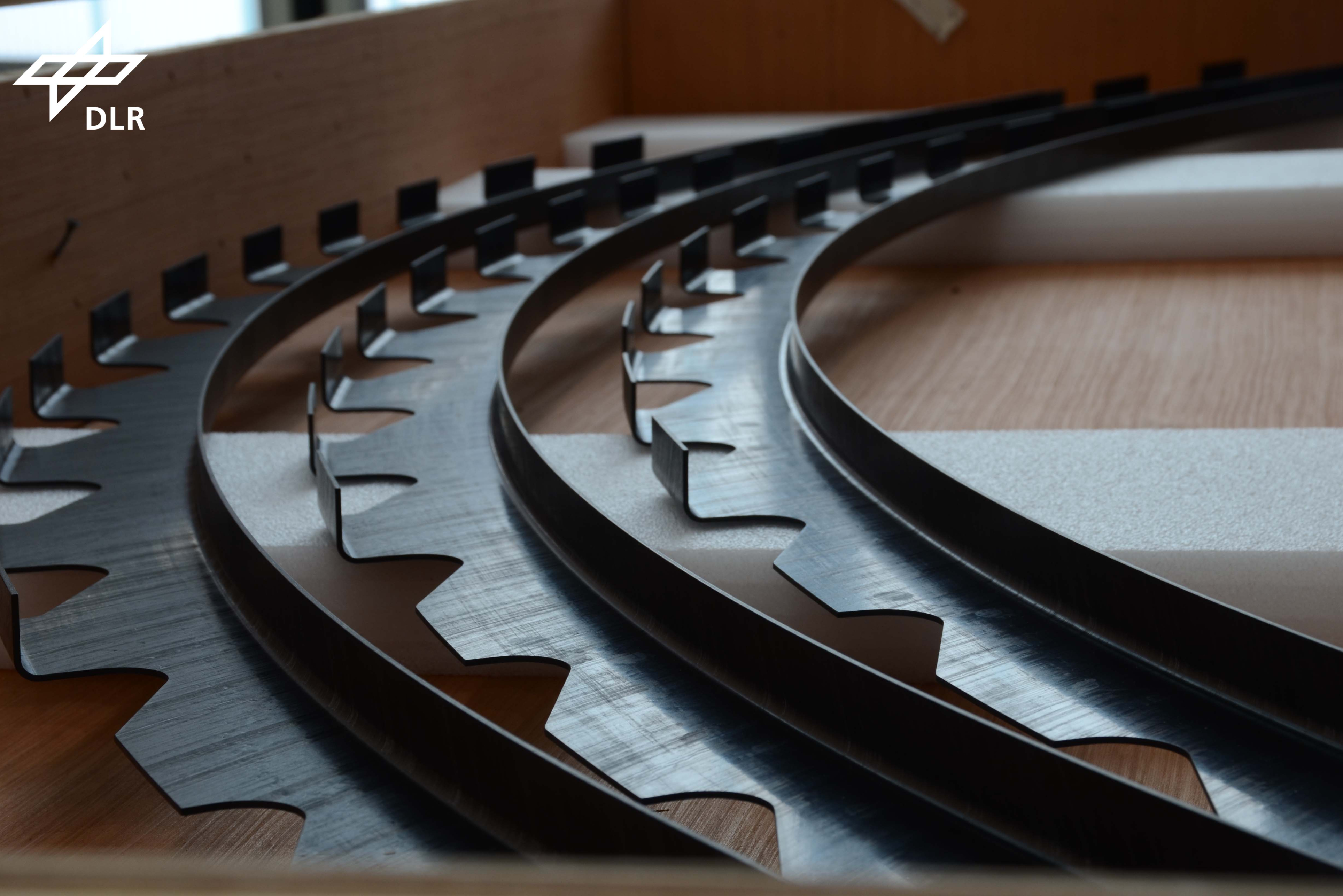
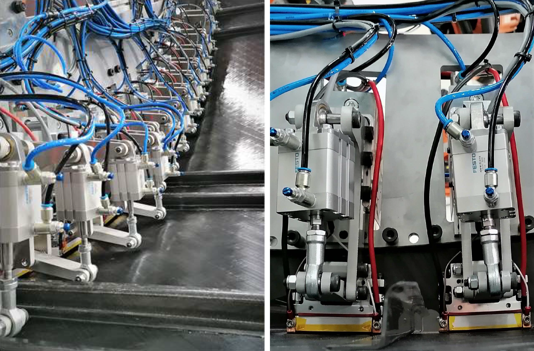
Fig. 3. Resistance-welded frames in upper MFFD
DLR’s curved welding bridge (top) is used to resistance weld fuselage frames (center), produced by Premium Aerotec (Augsburg, Germany), to the test fuselage skin. The bridge has a welding module for each frame foot, applying 6 bar of pressure with a pneumatic cylinder and electrical current from the red to black wire (bottom) which heats the matrix to its melt temperature. Photo Credit: DLR CC BY-NC-ND 3.0.
DLR’s resistance welding bridge can be seen in Fig. 3, anchored to the test fuselage shell tool. The bridge grips a curved fuselage frame and presses it down onto the skin. “Every foot along the frame has its own welding module with a pneumatic cylinder to apply a pressure of about 8 bar,” says Fischer. “Electric current is then run through the welding module [from the red to black wire in Fig. 3, bottom] into the welding element positioned between the frame foot and the fuselage skin.” This welding element generates heat in the weldline, analogous to the energy director used in ultrasonic welding.
In the past, it was a stainless steel mesh, “but we now use the same carbon fiber composite as in the skin and frames,” says Kupke. “Though metal has better electrical conductivity, we have eliminated any foreign material in the weldline — it is a single homogeneous material throughout.”
“During resistance welding, we run current until the matrix reaches the required process temperature, which is above the crystalline melting temperature,” continues Fischer. “We then reduce the voltage in two steps, while pressure is applied, until the weldline cools down. Welding takes about two minutes.” After the frames, DLR again uses resistance welding to integrate cleats as shear ties between the Z-stringers and curved fuselage frames. “DLR developed a cobot-on-robot-based welding system for this process because it requires perfect positioning of each cleat between stringer and frame and must also allow for tolerance compensation.”
MFFD door structure
Another part of the MFFD project is the door surround structure (DSS) for the lower fuselage half, to be fabricated by Tier 1 airframer Aernnova Aerospace (Miñano, Spain) using induction welding. (Note, the DSS for the upper MFFD half was produced by Premium Aerotec in Augsburg, Germany.) To support this, Clean Sky 2 awarded the DEWTECOMP project to the R&D lab CETMA (Brindisi, Italy), aiming to weld structural frames with reinforcement parts such as gussets, wedges and fittings to produce a DSS with at least 15% weight savings and up to 75% energy savings versus a standard autoclave-cured thermoset structure.
“Another goal of this project was to develop an effective but flexible induction welding process,” says Giuseppe Buccoliero, advanced materials and process development engineer at CETMA. “Our strategy was to divide the entire structure into different subassemblies that can be welded with a very simple tool and linear weld path. These welded subassemblies are then welded and fastened to manufacture the door frame structure. We first developed the induction welding process for the CF/LMPAEK unitape, and then we followed a building block approach by testing from the coupon level to the component level and finally to the demonstrator level. We also developed a fully automated induction welding cell where the robotic arm movement and the induction welding equipment are fully integrated and controlled by a single PLC [programmable logic controller].”
CETMA also developed simulation that can predict not only thermal behavior in the weld, but also mechanical behavior, such as microcracking. “This helped us to optimize the welding process for each DSS component, taking into account the laminate design and part geometry,” says Buccoliero. CETMA scaled from coupons to panels with stiffeners, verifying weld performance through lap shear, compression and double cantilever beam testing, the latter for fracture toughness and comparing test data with simulation results. It then scaled up to weld the frame subassemblies. It completed the project in June 2022.
CETMA is now working with its equipment partner SINERGO (Valdobbiadene, Italy) and Advantech Advisory (Lloret de Mar, Spain) to commercialize its patented induction welding technology, including both gantry and robotic systems. “SINERGO will supply the equipment and integrate it at the customer facilities, and CETMA will work with the customer to fully understand the application and complete the necessary process development,” explains Angel Lagraña, co-founder of Advantech Advisory.
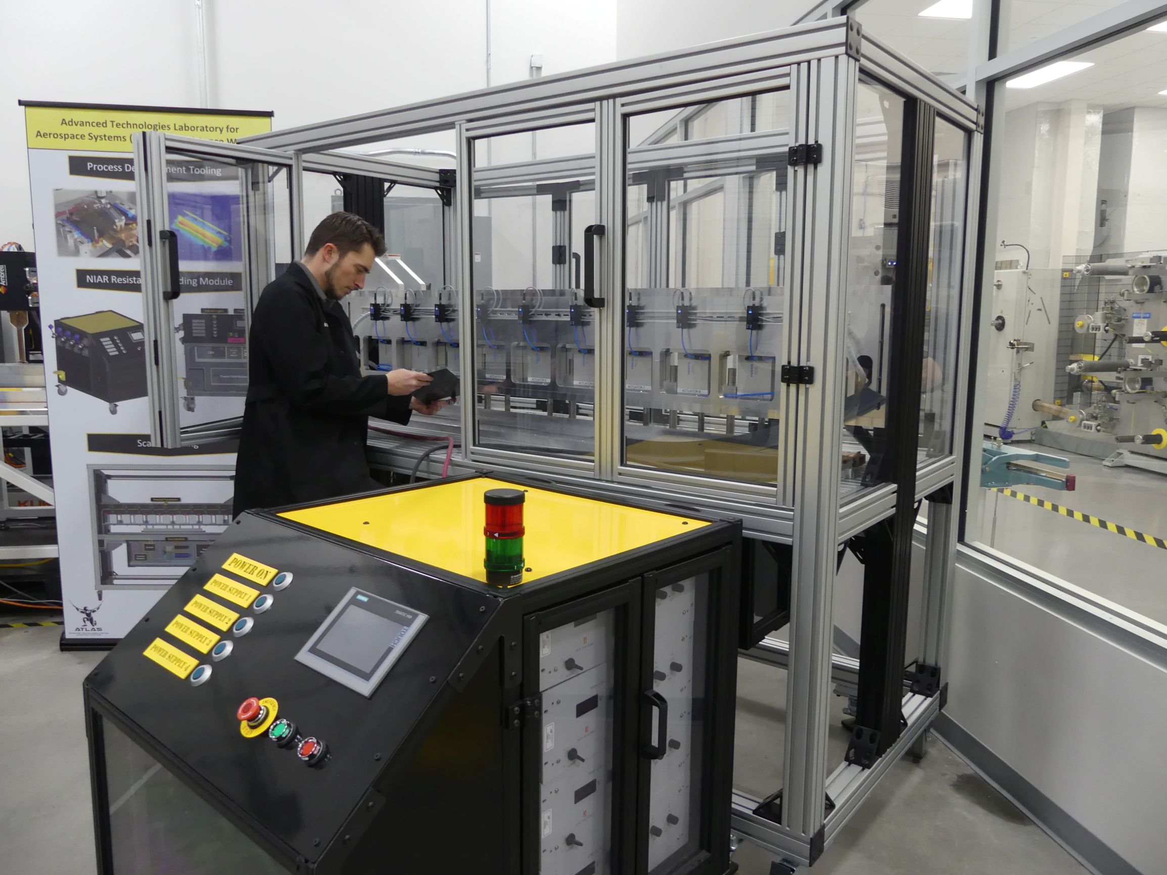
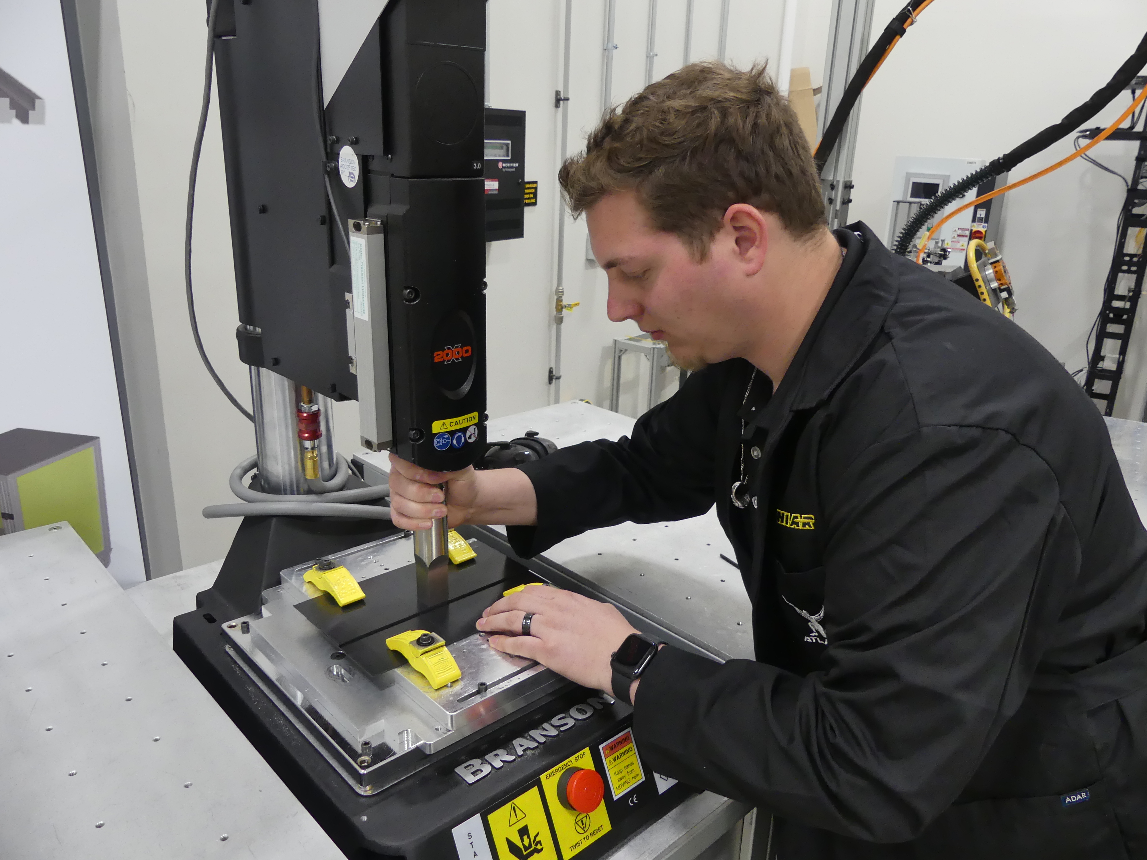
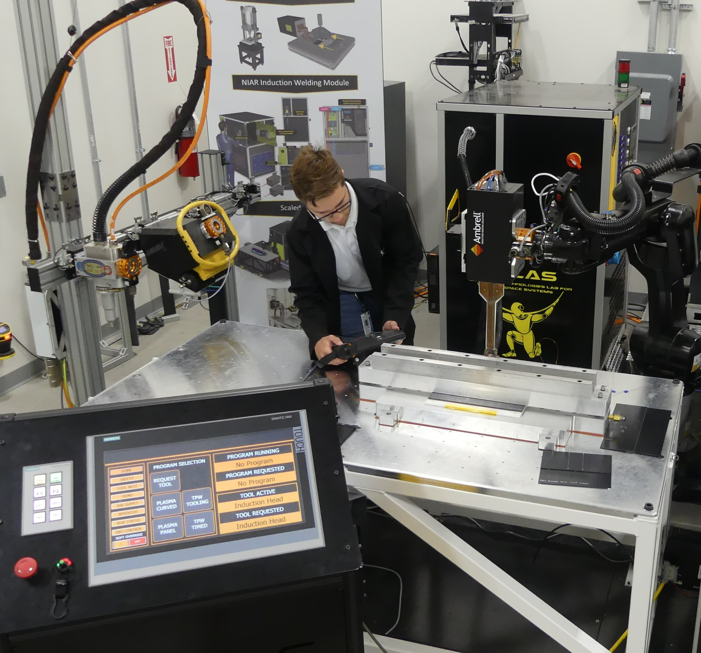
Fig. 4. Welding development at NIAR
ATLAS has added automated cells for resistance welding (top), spot ultrasonic welding (center) and induction welding (bottom) which will be used to produce a 30-foot-long demonstrator. Photo Credit: NIAR
NIAR
Wichita State University’s National Institute for Aviation Research (NIAR, Wichita, Kan., U.S.) is also developing resistance, ultrasonic and induction welding process specifications. In March 2021, it announced the addition of robotic induction welding equipment as part of its Modeling for Affordable Sustainable Composites (MASC) research program, sponsored by the U.S. Air Force Research Laboratory (AFRL, Dayton, Ohio). Its resistance welding and ultrasonic welding cells were added shortly after (Fig. 4), and are quasi-static, meaning they aren’t robot-based or continuous, but instead produce piece-wise welds. NIAR’s resistance welding uses carbon fiber resistance elements in the weld interface.
“Under this AFRL research, we’ll pursue process development and then building block certification protocols for all three welding technologies through a 30-foot-long manufacturing demonstrator called Frankenstein (FS-19),” says Waruna Senevirate, director of the Advanced Technologies Lab for Aerospace Systems (ATLAS) at NIAR. “This demonstrator will allow us to validate the in-house developed welding processes and certification protocols in scale and to work with different manufacturers to produce welded thermoplastic composite parts and make sure the processes are robust.”
The building block testing in this program will move quickly from coupons to the stiffened-skin panel element level, says Seneviratne. “We’ll do a comparison of bonded, bolted and welded joints in both in-plane and out-of-plane loading for static strength, durability and damage tolerance. We’re doing this because we need to address the issues with scaling these technologies. Fatigue testing is also key to understand long-term behavior. We have coupon-level fatigue data showing our resistance welds can perform 10 times better than bonded joints. But then we changed the quasi-isotropic ply at the interface from 45 degrees to 0 degrees, and just that small change quadrupled the fatigue performance. Yet in the static test data it showed no difference. Further, as we scale up in size, can we still hold this performance? This is important as you start to evaluate welding process parameters and different materials.”
NIAR’s welding development testing is using Toray TC1225 PAEK and Solvay Composite Materials (Alpharetta, Ga., U.S.) APC PEKK unitapes. Materials and welding techniques to be used for each part of the manufacturing demonstrator was to be finalized by September 2022. Lower level process development for all three welding technologies is to be completed this year. “We will then start moving on to our element-level testing and scaling from there,” says Seneviratne. “By summer 2023, we should be assembling parts in the demonstrator, with the goal to have it completed by 2025.”
KVE, Daher advance induction and IR welding
KVE Composites not only has more experience with welding (15 years) than almost any other company, but also boasts the only induction welding technology on flying aircraft, including the A220, Gulfstream G650 and Dassault F6X, which all use fabric-based laminates. KVE was acquired by Daher in 2019, which is helping to mature its patented KVE Induct technology for UD-based composites to TRL 4. The companies expect to reach TRL 5-6 with completion of the TRAMPOLINE full-scale horizontal tailplane (HTP) demonstrator in 2024 and aim to qualify that process with Boeing and Airbus, targeting a flying application by 2026.
The Daher-led TRAMPOLINE project, funded by CORAC (French Civil Aviation Research Council), targets a 15% weight reduction and significantly reduced subassembly cycle time versus thermoset composites. Its 2.5-meter-long HTP demonstrator derives from Daher’s TBM single-engine turboprop business/light utility aircraft and features curved surfaces and LMPAEK unitape laminates ranging in thickness from 1.6 to 8 millimeters. Daher’s knowledge of the part and loads will reportedly enable the project to mimic a full certification process.
In May 2022, Daher announced a three-year agreement with Luxembourg Institute of Science and Technology (LIST, Esch-Sur-Alzette) to develop infrared (IR) welding technology suitable for thick parts with large dimensions in high-volume manufacturing. “Daher invested in KVE because we could see the importance of its technology,” says Michael Hugon, intellectual property manager at Daher, “but from the beginning, we knew this is not the only way to weld. We are working with KVE to investigate the limits of induction welding, and KVE agrees that we need to also invest in alternative technologies that could be complementary.”
In IR welding, he explains, IR heaters preheat the weld faces directly, which are then pressed together. During induction welding, heat is induced in the carbon fiber laminate using an electromagnetic field. “Thus, energy must go through the thickness of one part to heat the interface and melt the thermoplastic matrix,” adds Hugon, “whereas IR welding is a simpler process. In our stamping process, we use IR heating to soften plies in a composite blank before shaping it into a 3D part. We have done this with fuselage clips for ten years now, but also in R&D of larger parts.” Daher has developed CF/LMPAEK ribs, up to 2 meters long and up to 12 millimeters thick, for Airbus’ Wing of Tomorrow program. “IR welding uses the same heat mechanism as our stamping process, but only heats the outer surfaces, after which we press two parts together,” continues Hugon. “Induction welding works well for closed box structures, such as the torsion box we have demonstrated in the TRAMPOLINE project. But we are studying what the advantage is for each technology. We are using synergy between KVE and LIST, involving welding experts and materials experts, to define specific component demonstrators for this comparison.”
“A first target for IR welding is to imagine new concepts for large and thick wing ribs,” says Bailly. “We have used induction welding for joining 8.5-millimeter-thick UD laminates, but we don’t yet know its limits, and its performance depends on whether fabric or UD laminates are used. We want to optimize both induction and IR welding in parallel and provide scientific data for certification.”
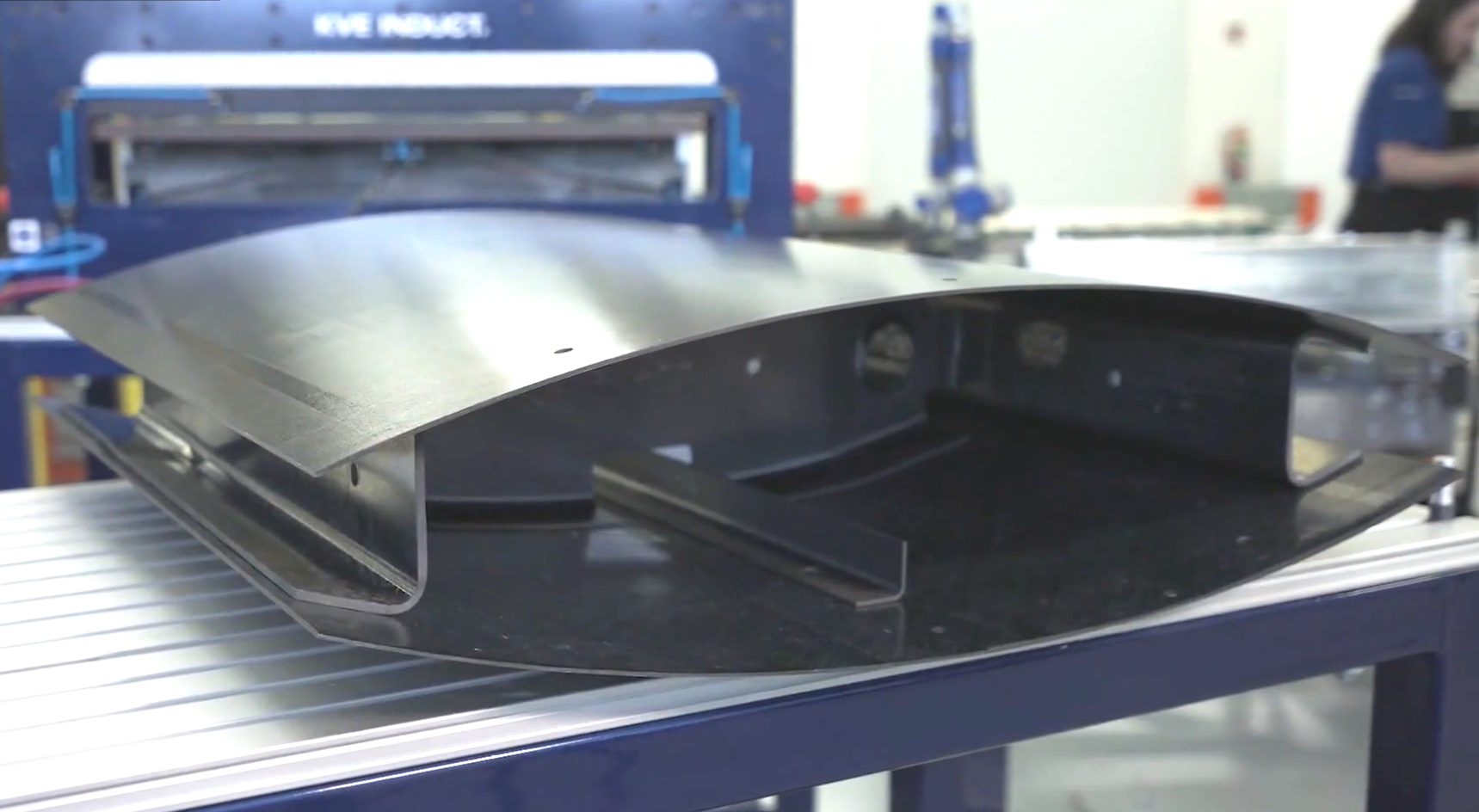
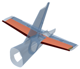
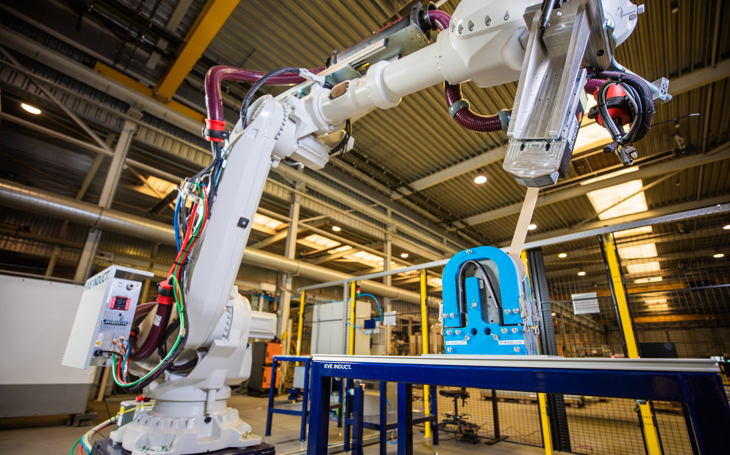
Fig. 5. Induction welding torsion box
KVE Composites and Daher have demonstrated a sub-scale torsion box demonstrator (top, see KVE digital demo), which will be followed by a full-scale business jet horizontal tail plane (HTP) torsion box (center) in 2023. KVE has commercialized both static and robotic welding cell (latter shown here, bottom). Photo Credit: KVE Composites, Daher
“We’ll also work to extrapolate design guidelines for business jet-scale structures in 2023-24, by scaling from the TBM-based HTP [Fig. 5] to a vertical tail plane,” adds Eloy. When asked if such structures might be possible after Airbus’ first planned ZEROe aircraft in 2035, he counters that hydrogen may work for regional turboprops, but faces too many challenges to cover the single-aisle jetliner mission. “We see the next challenge will be to reduce the weight of the next-gen single-aisle aircraft using thermoplastic composites and then use sustainable aviation fuel to meet zero emissions goals.”
Bailly agrees: “The small torsion box demonstrator we showed this year is a good step, but next year we’ll be assembling a 1:1 scale HTP, which will be tested to show TRL 6 in 2024.” To facilitate such developments in the market, KVE has commercialized a compact welding cell, used for welding of standardized SLS and L-profile pull-off coupons, and a larger, more versatile robotic cell for demonstrators and serial production.
Mobile susceptor induction welding
Induction welding is also being advanced by the Institut de Soudure (IS Groupe, Villepinte, France) and Arkema (Colombes, France) via its patented ISW process. As explained in a 2020 blog, IS Groupe induction welded stringers in the Arches TP fuselage demonstrator with Tier 1 supplier STELIA Aerospace (reorganized as Airbus Atlantic in January 2022). It subsequently reworked its dynamic, robot-based process to use a mobile susceptor that is linked to the welding head. Heated by an induction coil in the weld head, the metal susceptor focuses that heat precisely at the weld interface (Fig. 6). The mobile susceptor is used in combination with a pure thermoplastic or low-fiber-volume interface ply to augment resin flow.
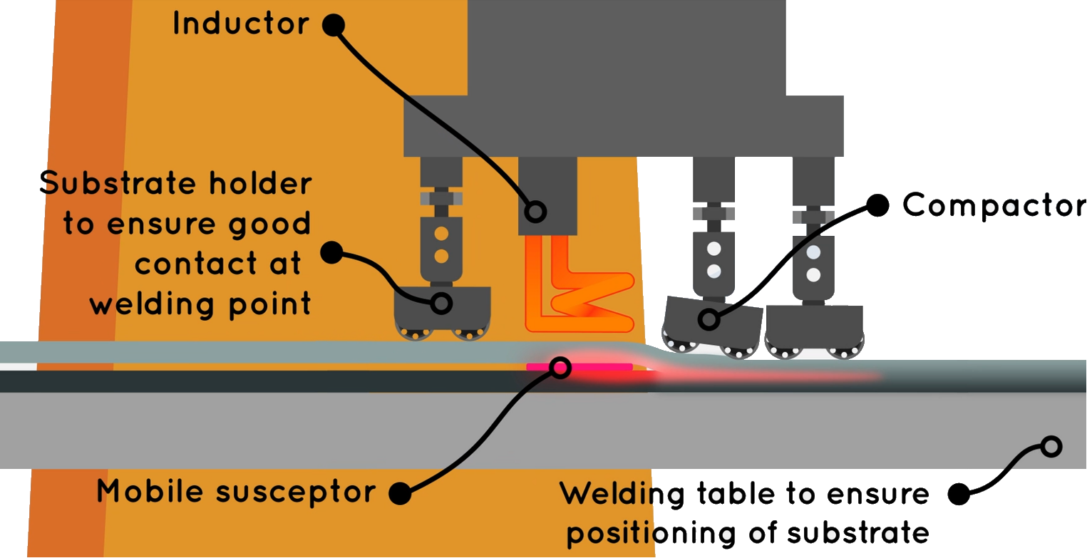
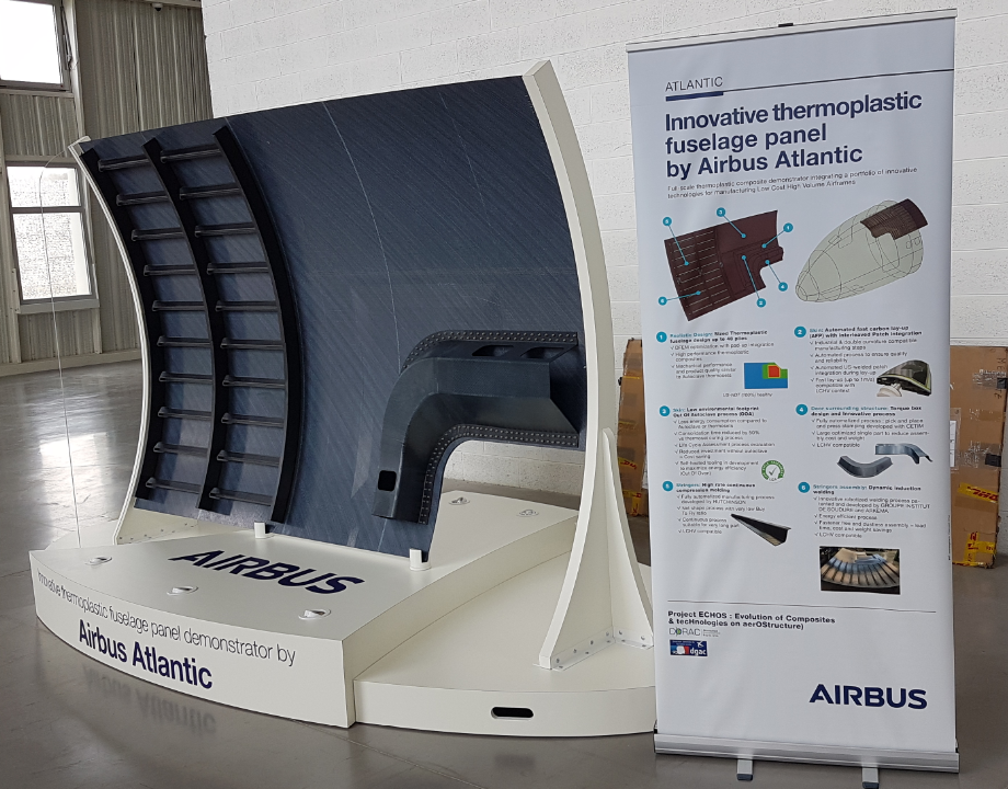
Fig. 6. Mobile susceptor induction welding
Using a metal susceptor that moves with the induction welding head (top) allows the ISW process to focus heat only at the weld interface. Used to produce the ECHOS fuselage demonstrator (center), the second-generation system shown here will soon have integrated inline NDT. Photo Credit: IS Groupe
ISW process development has mostly used unitape materials made with Arkema’s PEKK polymer. Interface plies have been tested using unreinforced PEKK and PEI film as well as UD tape with 35-40% carbon fiber by volume. Welds without an interface ply have also been conducted on skin/stringer plates made using UD CF/PEKK tape in quasi-isotropic layups of 7-39 plies ranging in thickness from 1.5 to 8 millimeters. Tests on welded flat and curved panels show SLS strengths that are 100% and 80%, respectively, of autoclave-consolidated reference panels, and welds on panels with copper mesh lightning strike protection have been successful with no issues. In 2021, IS Groupe worked with Airbus Atlantic in the CORAC-funded ECHOS (Evolution of Composites and tecHnologies on aerOStructure) program to demonstrate a 6-square-meter curved fuselage panel with ten 1-meter-long stringers welded using the ISW process. IS Groupe has commercialized first- and second-generation ISW welding heads and developed inline NDT using ultrasonic testing. It aims to reach TRL 6 in 2023 when it completes integration of this inline NDT into its welding platforms.
Welding development at Raytheon Technologies
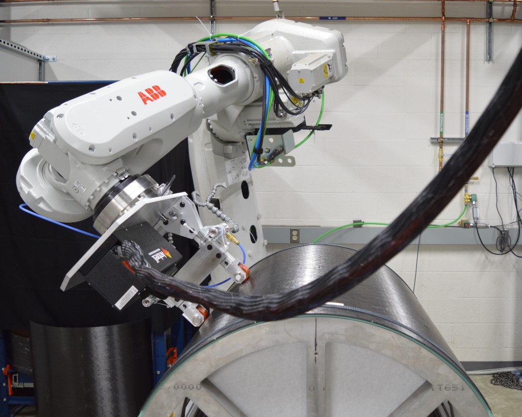
Fig. 7. Induction welding at Raytheon Technologies
Trials on curved panels conducted using a robotic induction welding cell with in-situ process control. Photo Credit: RTRC
Raytheon Technologies Research Center (RTRC, East Hartford, Conn., U.S.) has conducted induction welding trials on large, curved panels (0.825-meter nominal inner diameter, 0.876-meter-long outer arc, 1-meter long) comprising 16-24 ply laminates of CF/PAEK unitape representing a sub-scale, typical stiffened-skin aircraft structure. Dr. Wenping Zhao presented this work at SAMPE 2022 (May 23-25, Charlotte, N.C., U.S.), which included development of in-situ process control using a nonlinear model predictive control approach and offline simulation that optimized the induction coil speed along the curved weldline to meet the temperature requirements for a high-quality weld. The optimization relied on a numerical model describing the spatial-temporal heat evolution in the weldline, verified by physical experiments.
Peak temperature variation and average weld speed across the 0.876-meter weld path was ±20°C and 1.68 millimeters/second for uniform skin thickness and ±25°C and 1.6 millimeters/second for non-uniform thickness panels. Process parameter development began with flat panel testing on the KVE welding test setup at the University of South Carolina (Columbia, S.C., U.S.), which also helped to develop thermoplastic-coated optical fibers embedded into the composite laminate and interrogated using Luna’s (Roanoke, Va., U.S.) ODiSi6100 eight-channel interrogator system.
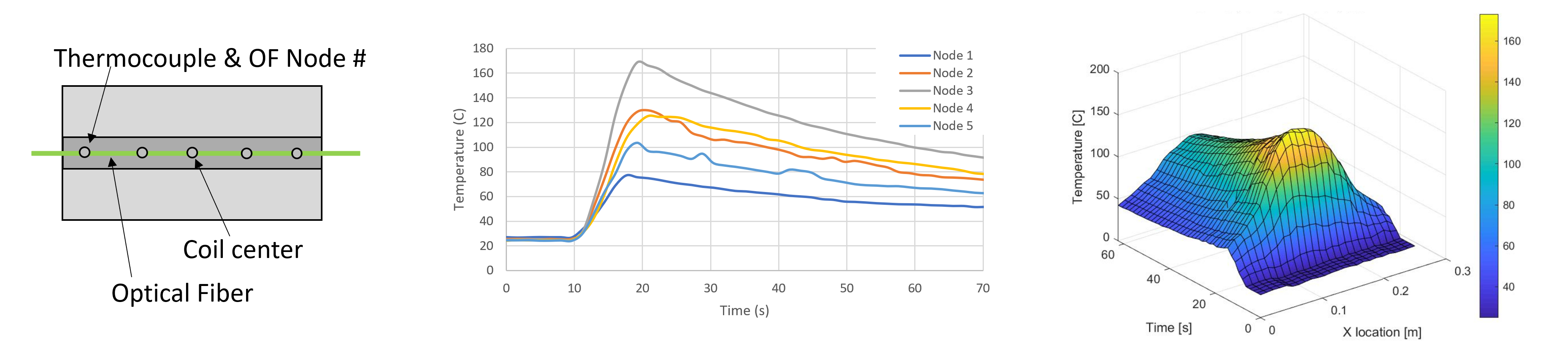
RTRC and University of South Carolina used optical fibers (OF) in the weldline of the curved panel induction welding trials. Shown here: Placement of these OF sensors and thermocouples (left), as well as 2D and 3D temperature distributions (center and right) measured in the weldline. Photo Credit: Dr. Wout De Backer, University of South Carolina, from Fig. 8, “Automated induction welding of large thermoplastic composite structure,” SAMPE Conference Proceedings. Charlotte, NC, May 23-26, 2022.
RTRC also used force/torque sensors in its robotic induction welding head, an IR camera and thermocouples to monitor pressure and temperature during welding. Zhao acknowledged support provided by the Advanced Robotics for Manufacturing (ARM) Institute (Pittsburgh, Pa., U.S.), GrayMatter Robotics team led by Dr. Ariyan Kakir and the University of South Carolina team, led by Dr. Wout De Backer and by Dr. Michael van Tooren (technical fellow structures at Collins Aerospace, previously at U of S.C.) regarding induction welding. “We have a follow-on program to further improve welding quality by applying machine learning,” says Zhao. “As the technology matures, our aim is to transition to a large part demonstration.”
Process control, NDT, certification, crack arresters
What parameters must be monitored and/or controlled to ensure a good weld? “With composites, we must always know that the part saw the right temperature, pressure and time,” says Kupke at DLR. “We monitor and log these for every weld.” How this is done varies per welding technique, from tracking power to the weld head, along with its speed and integrated force sensors, to infrared (IR) cameras monitoring the part surface temperature (and correlated to the weldline temperature) to optical fibers actually embedded in the weldline. Most technologies rely on optimizing process parameters during months of testing and then monitoring and logging that welding conforms to this specification on actual parts. Ultrasound NDT is also being used, both post-weld and integrated into the welding system for inline inspection, and noncontact methods are being researched for larger areas and higher part volumes.
Research is also pursuing artificial intelligence (AI) to certify and link process parameters to weld quality but also to fully automate robotic welding. “I don’t want to manually teach the robot each time I weld,” says Van Rijswijk at SAM|XL. There are sensors that enable the robot to see what needs to be done and to program itself, he says, as well as monitor the material conversion, including consolidation, which is key for OEM certification.
“You basically have three approaches for certification of bonded or welded joints: full proof testing to limit load, full NDT inspection or some sort of crack arrest features,” says Seneviratne at NIAR. Crack arrest features (e.g., chicken rivets) are used today in bonded primary structures, metal and composites, as well as the welded thermoplastic composite rudders and elevators that are flying, due to the failsafe requirements of current certification protocols. “Eventually, I think we’ll have enough confidence for welded composite primary structures without crack arrest features,” he says, but conditions this on first building years of history and data, “like we have done for bonded joints.”
This is a brief summary of the full “Part 2” of this article, available online: “Thermoplastic composites welding: Process control, certification, crack arresters and surface prep.” That discussion ends with Bach at KVE noting increased requests for welding systems, as well as increased investment into welding technology overall and demand for the next step in sustainability that it brings. His assessment: “We will see more welded thermoplastic composites flying within a decade.”


.jpg;maxWidth=300;quality=90;format=webp)


Related Content

Materials & Processes: Fabrication methods
There are numerous methods for fabricating composite components. Selection of a method for a particular part, therefore, will depend on the materials, the part design and end-use or application. Here's a guide to selection.
Read More
PEEK vs. PEKK vs. PAEK and continuous compression molding
Suppliers of thermoplastics and carbon fiber chime in regarding PEEK vs. PEKK, and now PAEK, as well as in-situ consolidation — the supply chain for thermoplastic tape composites continues to evolve.
Read More
Novel dry tape for liquid molded composites
MTorres seeks to enable next-gen aircraft and open new markets for composites with low-cost, high-permeability tapes and versatile, high-speed production lines.
Read More
Materials & Processes: Fibers for composites
The structural properties of composite materials are derived primarily from the fiber reinforcement. Fiber types, their manufacture, their uses and the end-market applications in which they find most use are described.
Read MoreRead Next

Composites end markets: Energy (2024)
Composites are used widely in oil/gas, wind and other renewable energy applications. Despite market challenges, growth potential and innovation for composites continue.
Read More
CW’s 2024 Top Shops survey offers new approach to benchmarking
Respondents that complete the survey by April 30, 2024, have the chance to be recognized as an honoree.
Read More
From the CW Archives: The tale of the thermoplastic cryotank
In 2006, guest columnist Bob Hartunian related the story of his efforts two decades prior, while at McDonnell Douglas, to develop a thermoplastic composite crytank for hydrogen storage. He learned a lot of lessons.
Read More