


More sustainable CFRP fuselage shells for next-gen rotorcraft
Fraunhofer IGCV worked with Airbus Helicopters to develop an AFP-based process and deliver one shipset of right and left side shells for the fuselage of the RACER demonstrator helicopter. Photo Credit, all images: Clean Aviation, Airbus Helicopters, Fraunhofer IGCV
The RACER (Rapid and Cost-Efficient Rotorcraft) is a demonstrator within the Fast Rotorcraft Innovative Aircraft Demonstrator Platform (FRC-IADP), part of the EU-funded Clean Aviation program. RACER aims to demonstrate a new compound rotorcraft architecture that is not only significantly faster and lighter than a conventional helicopter — vital for emergency medical and search and rescue operations — but can also be produced using more ecologically sustainable and cost-effective processes.
CW explored development of RACER’s forward fuselage structure in the 2021 article, “Leveraging motorsports technology for next-gen rotorcraft.” As assembly of the RACER demonstrator is completed and the rotorcraft proceeds toward first flight, this report focuses on the novel automated process used to produce the fuselage side shells, featuring honeycomb-cored carbon fiber-reinforced polymer (CFRP) sandwich construction.


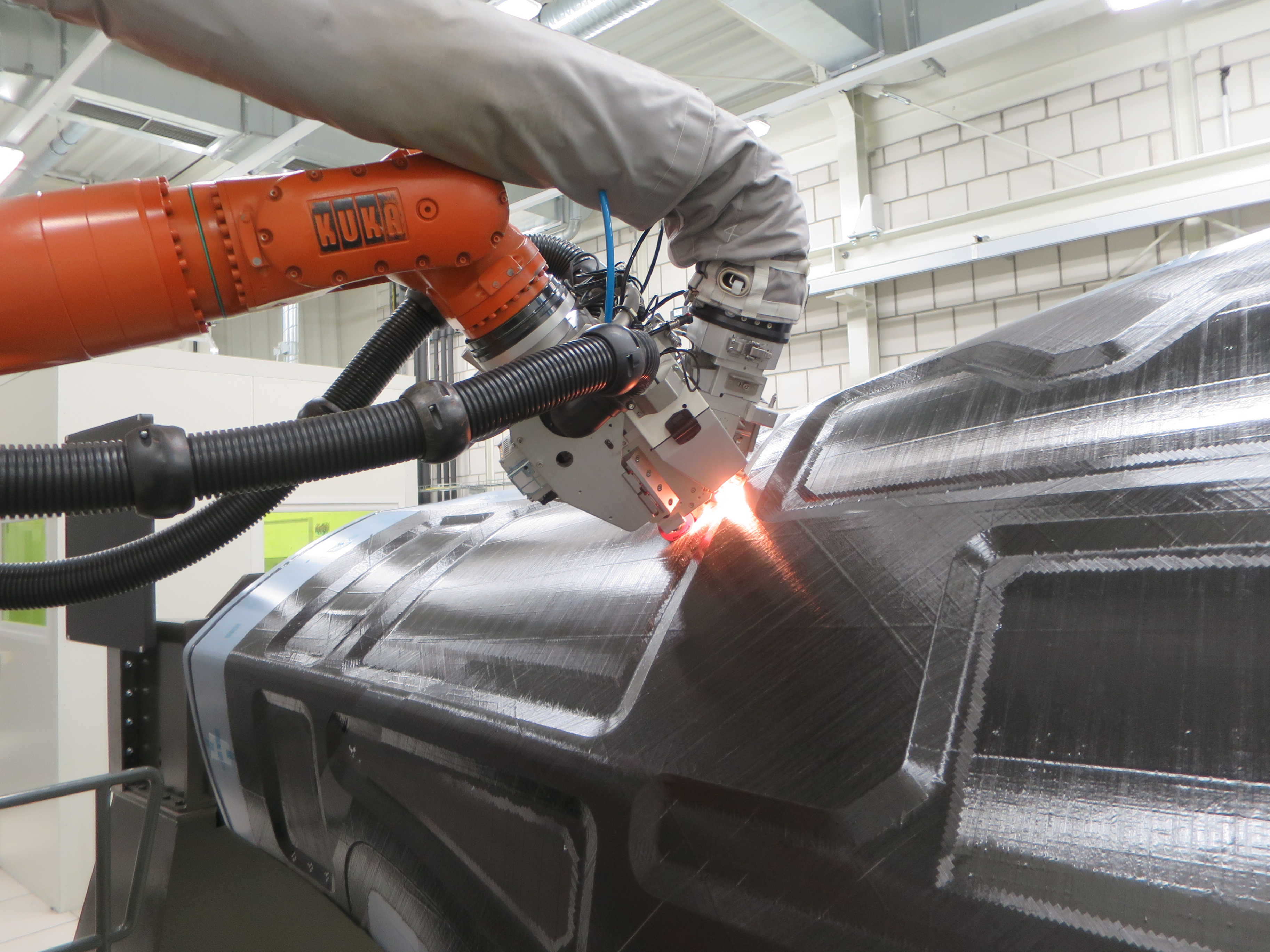
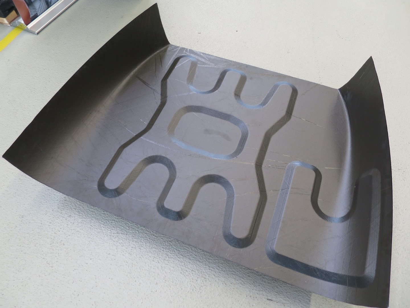
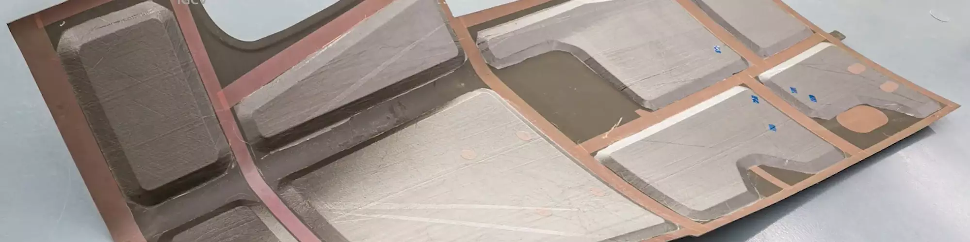
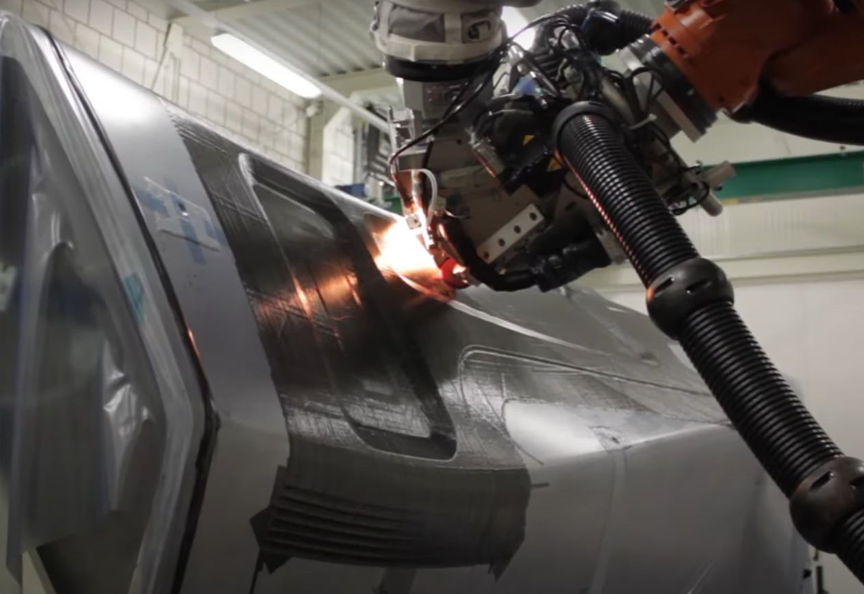
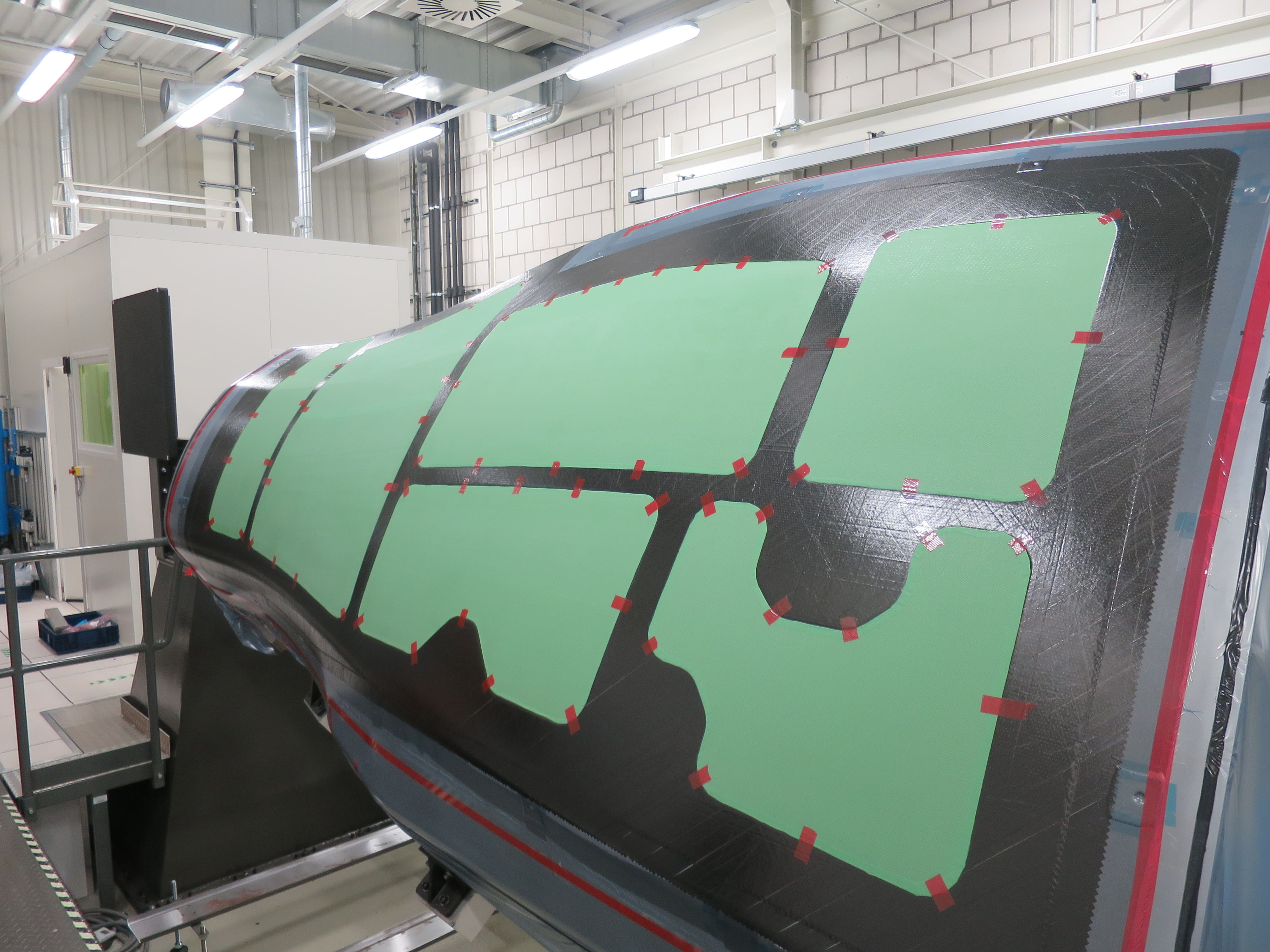
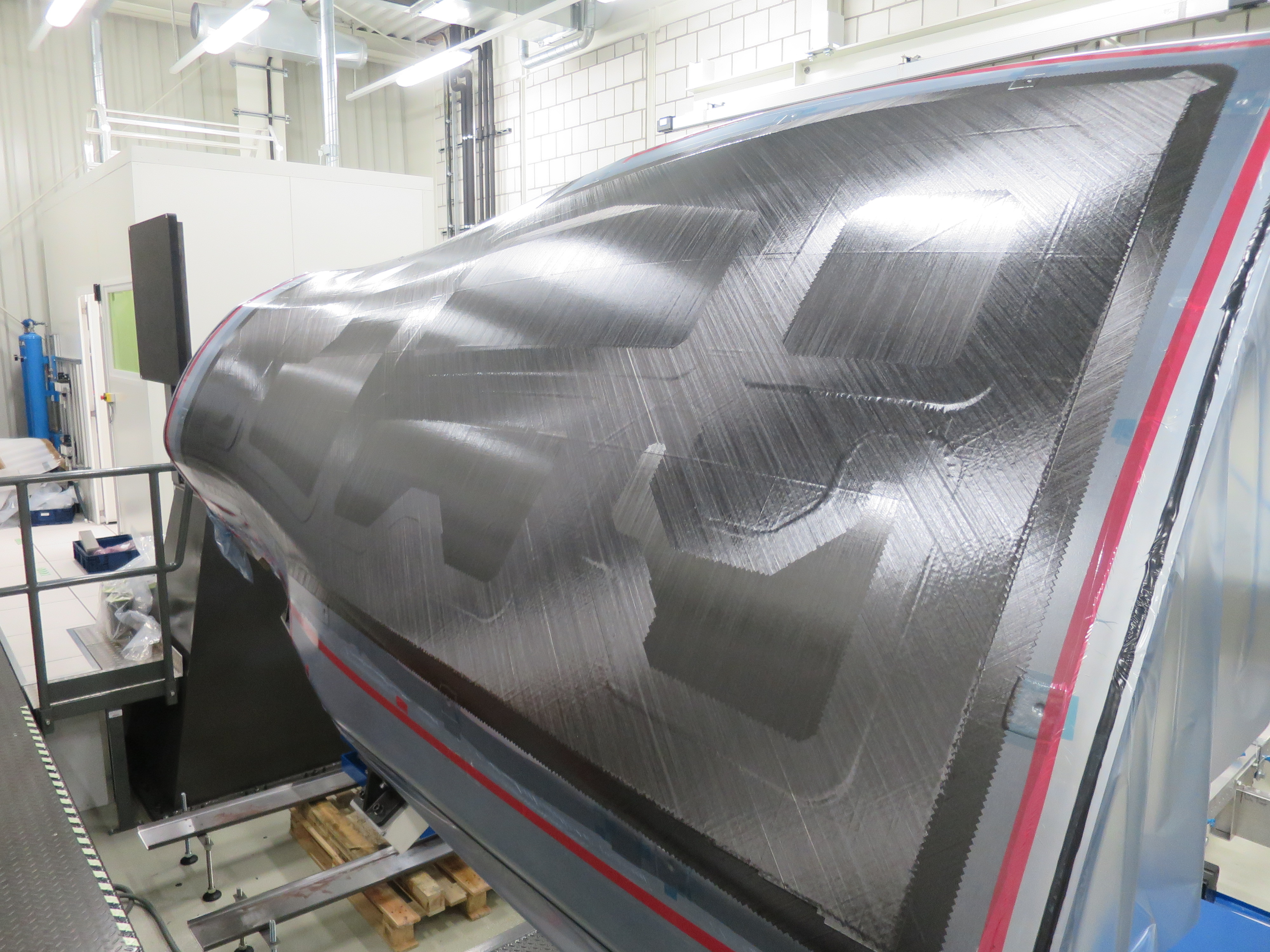
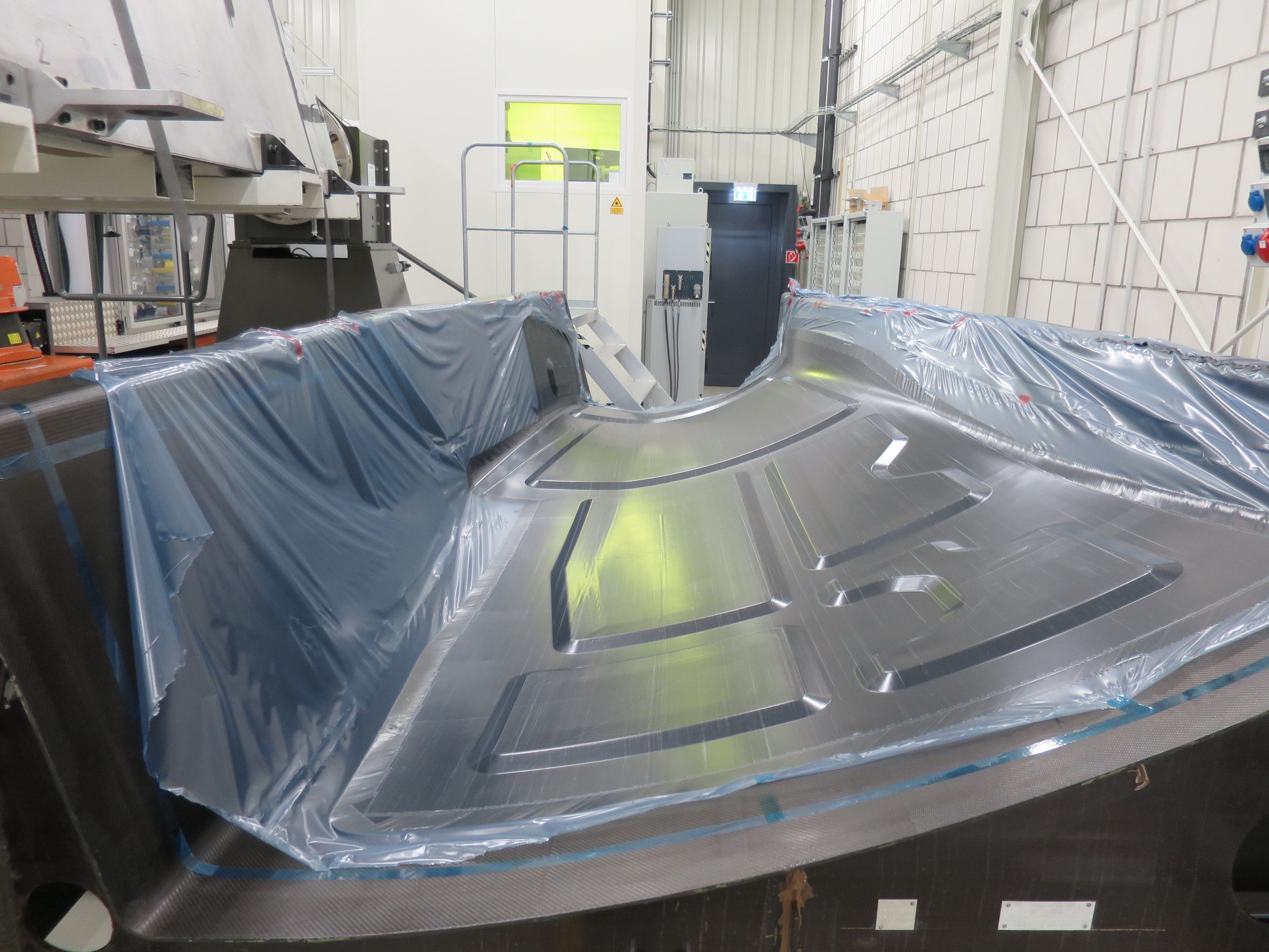
Fig. 1. AFP process, cored parts
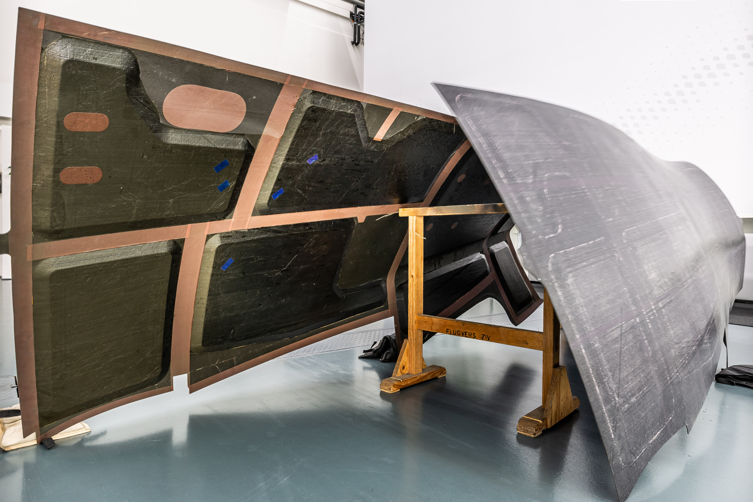
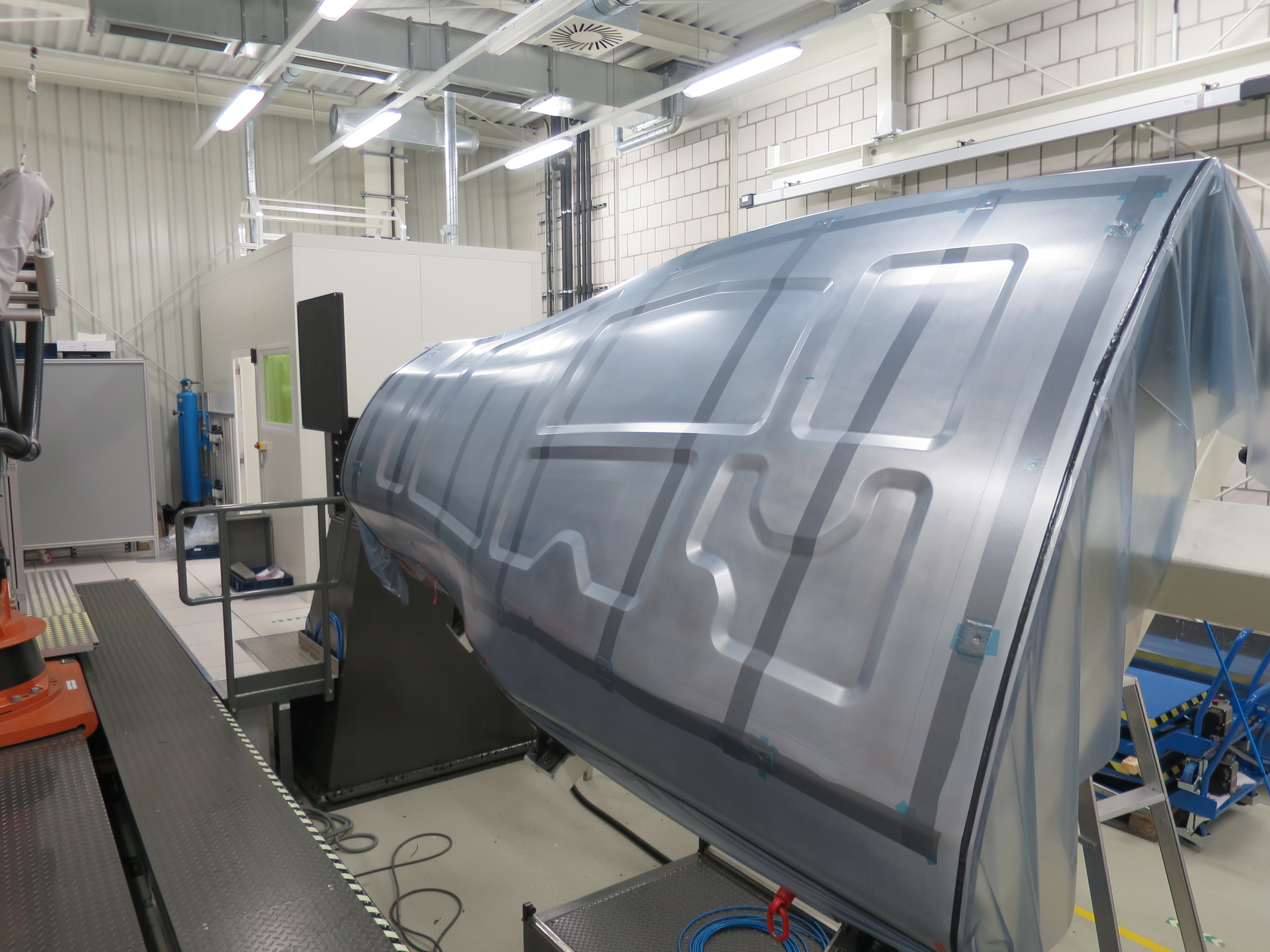
Fraunhofer IGCV proved its AFP-based process chain first on 1.2 ×1.0-meter feasibility parts (bottom) and then on side shells for the RACER demonstrator (top) which featured eight tapered pockets for honeycomb core.
Project leaders, Airbus Helicopters’ site in Donauwörth, Germany, and the Fraunhofer Institute for Casting, Composite and Processing Technology IGCV (Augsburg, Germany), overcame significant challenges to develop a process chain that optimized automated fiber placement (AFP) for cored structures. They also used male layup tooling, female cure tooling and a film-based transfer of the layup in between to meet part and manufacturing requirements.
“The side shells are in the rear of the helicopter’s airframe, attached directly to the tailboom,” explains Thomas Zenker, one of the lead researchers for the RACER side shells project at Fraunhofer IGCV, who now works as a composites materials and process engineer at MT Aerospace (Augsburg, Germany). “Our project ran for almost four years,” he continues, “from November 2016 to September 2020, with the goal to develop an automated manufacturing process that would deliver two airworthy side shells for the demonstrator helicopter. The process also had to show reduced ecological impact and increased economic performance.”
The project successfully produced a 1.2 × 1.0-meter feasibility part (Fig. 1), followed by one shipset of 3.4 × 1.5-meter left and right rear section side shells. It also demonstrated 8-15% improvement in potential greenhouse gas emissions, 20-45% reduction in CFRP production waste and 20% cost savings compared to current hand layup processing. Further, the project showed that AFP can be profitable for small-series production — cost parity with hand layup was calculated at 12 shipsets per year.
Project partners, process challenges
Airbus Helicopters has a long history innovating composites (see “Composite ring frame improves safety, cost for workhorse helicopter”). Its partner in this project, Fraunhofer IGCV, was formed in 2016 and focuses on lightweight design and intelligent manufacturing processes. Examples of its focus on casting, composites and process technology research include low-cost sophisticated casting processes for metal parts, CFRP manufacturing engineering for novel processes and networked modeling and simulation solutions. These technologies played key roles in the RACER side shell project and are discussed below.
The shells’ CFRP sandwich design was specified by Airbus Helicopters. “Helicopters require very lightweight structures, and sandwich construction helps to achieve that,” explains Jürgen Filsinger, head of manufacturing processes at Fraunhofer IGCV.
“Cored sandwich construction also provides buckling stiffness in this type of helicopter fuselage shell structure,” adds Zenker, “but most parts currently in production are based on hand layup.” Although AFP has been matured for automating layup of monolithic CFRP structures, it is still relatively new for use with honeycomb-cored parts. “There has been concern about damaging core during AFP,” he explains. “For the RACER side shells, we used an approach which avoided AFP on top of positive core geometries. However, it is also possible to use AFP on such geometries without damaging the core.”
The side shells’ sandwich design would be achieved by AFP on a complex-shaped tool to create an inner mold line (IML) skin with eight “pockets” of various shapes and sizes, featuring a 20° ramp angle and 15-millimeter depth. Machined honeycomb core would then be inserted into the pockets, resulting in a flat surface onto which AFP was used again to lay up the outer mold line (OML) skin. This design, combined with the part’s double curvature and tight radius at the tailboom interface, caused several technical challenges.
“The first was how to get the high-quality fiber architecture required during AFP of unidirectional [UD] tapes despite ramps and curvature,” notes Zenker. “The second challenge was the AFP layering process itself. How would the ramps for integrating the sandwich cores affect our layer quality and how do we optimize the parameters and placement paths to minimize wrinkles, gaps and other defects? The third challenge was the process chain. We needed to find a manufacturing concept that allowed us to cure the part in a female tool to control the OML, but layup in a female tool would have resulted in collisions between the AFP head and the tool. To ensure accessibility of the AFP head to the complex ramps within the double-curved geometry required layup on a male tool.”
Issues in AFP layup design
The first challenge required devising an AFP layup strategy that met the boundary conditions set by Airbus Helicopters. These included the requirement that angular deviation of placed fibers compared to the CAD layup architecture be no less than 5°. Also, the coverage ratio — the fraction of the surface covered by fiber as compared to gaps — had to be maximized while defects caused by fiber steering had to be minimized. Although these requirements were fairly standard, the challenge was to meet them while achieving the side shells geometry, which required fiber steering.
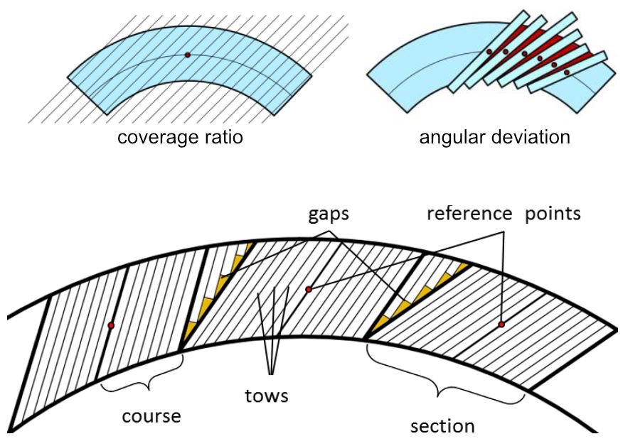
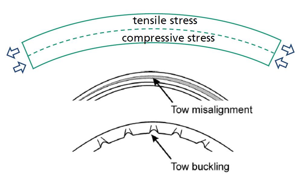
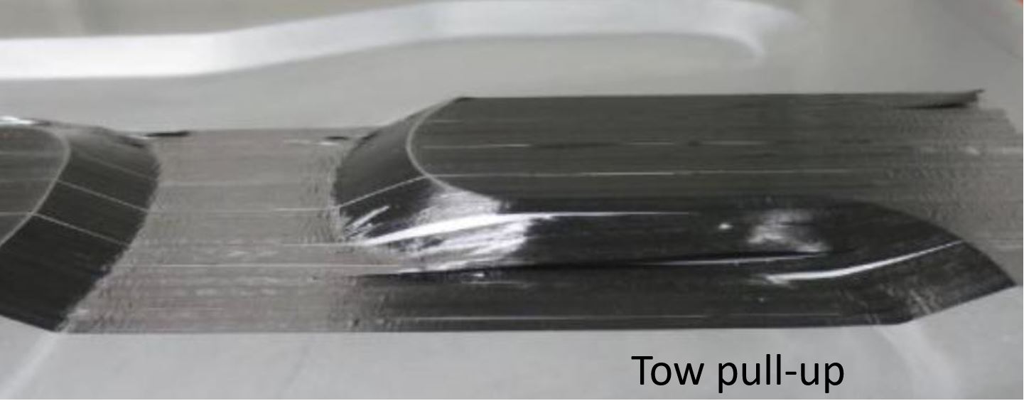
Fig. 2. AFP boundary conditions and defects
The RACER side shell geometry posed challenges for developing an AFP layup strategy that met boundary conditions of maximized coverage ratio, <5° fiber angle deviation and minimized steering to avoid defects such as tow misalignment, tow buckling and tow pull-up. The top two diagrams show triangle-shaped gaps created by perpendicular cut tapes. Photo Credit tensile/compressive stress, tow misalignment and buckling: Dirk H.-J.A. Lucaszewicz, et al., “The engineering aspects of automated prepreg layup ...”, Composites Part B: Engineering, 2012.
Fiber steering is used to apply tapes to complex 3D geometries or to form curved shapes on a flat surface. The Coriolis Composites (Quéven, France) C1 AFP machine used by Fraunhofer IGCV for the side shells features a 6-axis robot with an AFP head that places up to 8 tows simultaneously — typically 0.25-inch/6.35-millimeter-wide UD prepreg tape — which results in a 2-inch/50.8-millimeter-wide course per AFP toolpath when all 8 tows are placed.
Designing a maximized coverage rate requires parallel adjacent AFP courses to be laid without overlaps or gaps, but achieving this in practice isn’t always straightforward on a double-curved surface. As explained in a 2020 paper by Zenker, et al., accommodating the side shells geometry required the C1 AFP head to make a rotation in the Z-axis, which is a form of fiber steering that creates in-plane bending of the tow. This produces tensile and compressive stress that can result in tow misalignment, tow buckling or tow pull-up (Fig. 2).
“The process and material defined our fiber steering limits to avoid these unwanted effects caused by steering stress,” says Zenker. The material used was Hexcel’s (Stamford, Conn., U.S.) AS7 carbon fiber/8552 epoxy resin prepreg UD tape slit to 6.35-millimeter-wide tows with 34% resin content by weight and 145 grams/square meter fiber areal weight. This prepreg was applied to the laminate for the feasibility part used to validate the team’s eventual AFP layup design; it was also used to fabricate the side shells. Neither this standard material nor the C1 AFP machine was an issue. The difficulty was how to achieve the part geometry while meeting all of the boundary conditions.
“With AFP, I can optimize every fiber directly and cover the area by parallel curves,” says Zenker, “but that wasn’t actually possible due to the large surface of the side shells combined with the geometrical complexity. For example, if we used a standard approach with our C1 machine, the part would be covered by 50.8-millimeter-wide courses, and we couldn’t comply with all of the boundary conditions. One reason for this is that the tape can only be cut perpendicular to the feed direction, which means that adjustments in the fiber angle result in triangular gaps [Fig. 2]. To avoid multiple zones of these gaps, fiber steering is used to generate an adjusted fiber architecture.”
AFP paths using standard approaches
Developing an optimized AFP layup strategy thus required managing a complex set of interrelated boundary conditions to minimize defects. Fraunhofer IGCV began by analyzing various AFP paths using the C1’s CATFiber 1.8.5.2 plug-in for CATIA V5 (Dassault Systèmes, Vélizy-Villacoublay, France) provided by Coriolis Composites. The CATFiber software tool imports the fiber architecture in the laminate stacking sequence from CAD, after which users can choose various strategies to generate the AFP toolpaths and then perform analysis and optimization. The team trialed three standard curve types used in AFP layup design:
- Parallel lines (parallels in Fig. 3) to an initial guide or reference curve based on the global axis of the part.
- Geodesic lines (shortest path between two points on a surface) shifted along the neutral fiber (reference line on IML surface that defines translation relative to 0°) to desired fiber angle using a standard 8-tow course.
- CATFiber line pattern (netcurves in Fig. 3) using the same basis as geodesic lines but controlled by fiber angle deviation limit.
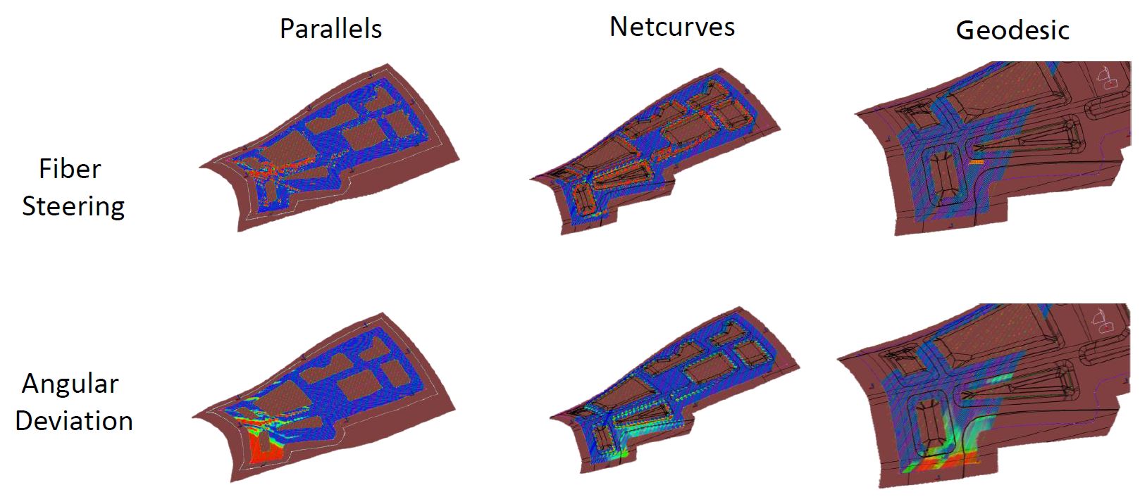
Fig. 3. Standard AFP path strategies violate boundary conditions
Fiber steering and angular deviation analyses for the three standard AFP layup strategies show values outside required tolerances in red and values within boundary conditions in blue.
None of the standard approaches provided a suitable solution. Results are shown in Fig. 3 where fiber steering and fiber angle deviations outside the tolerances are red; areas within limits are blue. “The simple parallels approach resulted in high angular deviations in double-curved areas and a high amount of fiber steering in those areas that were significantly distanced from the initial curve,” notes Zenker. “The geodesic approach avoided fiber steering, but the angular deviations were high and the coverage ratio was low, as triangular defects occurred between all courses. The curve pattern created with CATFiber showed good global results, but the AFP paths tended to deflect when going over ramps, resulting in high steering and local angular deviation in those areas.”
Knowledge-based template plus spline curve
What was needed, explains Zenker, “was a flexible AFP path generation strategy that allowed local adjustments to overcome the geometrical challenges. We developed a technique that uses what we call a knowledge-based template and a spline curve.”
A spline curve is a mathematical representation that provides an easy user interface to control the shape of complex curves. “We started with a base curve incorporating a number of spaced control points that can be adjusted to change the shape of the curve using the spline. Movement of these control points is done by the knowledge-based template which incorporates design parameters,” he continues. “This enables direct parametric control of the AFP path shape and, therefore, gives us the opportunity to optimize the fiber architecture in respect to the boundary conditions. For example, we can minimize fiber steering effects by local curve smoothing or redistribute geometrical gaps so that their size and shape comply with the requirements. The adjacent spline can be based on the first curve or on a new base curve. Either way, the shape of each curve can be controlled individually.”
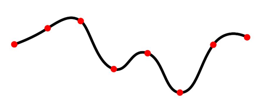
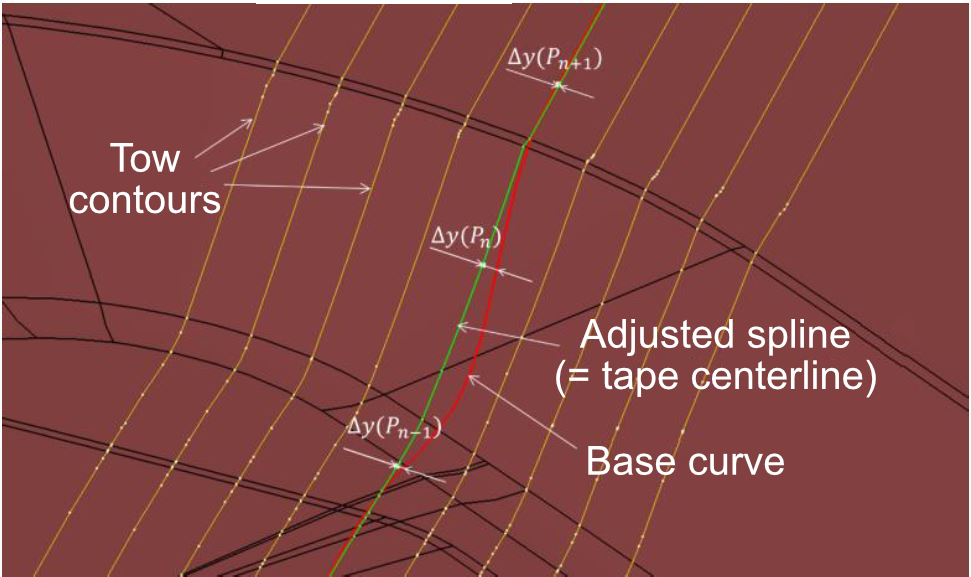
Fig. 4. Knowledge-based template + spline
Fraunhofer IGCV developed an AFP layup strategy that used a knowledge-based template (bottom) to adjust the points of a spline curve (top) to achieve parametric control of the AFP path shape.
Results of this method are shown in Fig. 4. “You have the base curve which runs quite well in the flat region of one of the pockets, until it hits the lower section of the ramp, where it deviates a lot from a curve that could meet the boundary conditions,” explains Zenker. “To solve that, you correct the points that are close to this section. For example, you can move the three points shown using parametric control and through small adjustments of 1 to 1.5 millimeters you get a fiber architecture that covers the part much better.”
The team was thus able to identify problematic layup regions and use the knowledge-based template to adjust the spline and complete the tow-by-tow modifications necessary to bring the overall layup within acceptable limits. “It wasn’t possible to reduce the angular deviation to zero due to required compliance with the other boundary conditions,” says Zenker, “but it was possible to stay well below the 5° threshold. It was also not possible to comply 100% with the fiber steering limit over the more tightly curved section, but we were able to achieve a coverage ratio close to 99%.” This was because the template and spline method enabled designing small longitudinal gaps instead of large triangular gaps in tow drop areas and ramps.
Optimizing process parameters
With an initial layup strategy finalized, the next step was to analyze the AFP process parameters to avoid common defects such as wrinkles, bridging and tow pull-up. “For this, we developed a feasibility part and selected a 4-tow course across the more complex curves and ramps,” says Zenker. “This section included a curved ramp-up and ramp-down as well as ramp-ups and -downs longitudinal to the layup direction and transverse to the layup direction. We then ran the AFP paths while varying parameters such as feed rate, heating rate and compaction force and studied the effects on the layer quality. We were thus able to address the most characteristic defects, like smaller wrinkles or fiber bridging in the lower ramp radius.”
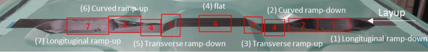
Experimental studies on AFP process parameters vs. layup quality
Fraunhofer IGCV chose a 4-tow course across the feasibility part to study and refine AFP process parameters to minimize defects, including wrinkling and bridging.
Film-based layup transfer
The final piece in developing the process chain was how to optimize layup and cure tooling. “It wasn’t possible to create the AFP layup in a female tool,” explains Filsinger. “We needed a male layup tool for accessibility. But we required a female cure tool to maintain the OML tolerance during the autoclave cycle. The solution we developed was to use a layup film that covers the male layup tool and is then used to transfer the AFP layup onto the female curing tool.”
Step 1. A stretchable transfer film was applied to the male layup tool.
Step 2. AFP was used to layup the side shell’s inner mold line (IML) skin.
However, the team had to find a film that would work in this layup and transfer process. “It had to be stretchy and cover the layup tool without creating any wrinkles,” says Filsinger. “It would be applied to the layup tooling first, and then after the layup was finished, the cores were placed and the AFP top skin was placed over the cores. After this, the layup and cure tools were aligned using locator pins in the tooling. The layup on the film was then transferred from the male tool to the female curing tool.” The film selected was Strechlon 350HT, a thermoplastic elastomer high elongation vacuum film from Airtech International (Huntington Beach, Calif., U.S.).
“In order to try out this film-based process chain as well as the parameters, we designed and fabricated a feasibility part,” says Filsinger. “It was somewhat smaller than the full-scale side shell, measuring 1 meter by 1.20 meters and used 4 plies of UD CF/epoxy prepreg tape for both the inner and outer skins.” The stacking sequence was [0°/+45°/90°/-45°]s where the “s” denotes a symmetric layup, meaning that with the honeycomb at the midplane, ply orientations above the core were mirrored below it.
Step 3. Machined honeycomb core sections pre-wrapped with core film adhesive were inserted into the core pockets in the side shell’s IML layup.
“We made two of these feasibility parts, using two types of core material,” adds Filsinger. The first part used standard Nomex honeycomb core with a density of 48 kilograms/cubic meter and a 3.2-millimeter cell diameter. This was also used for the final demonstrator parts. The second feasibility part used Rohacell polymethacrylimide (PMI) foam core from Evonik (Essen, Germany). “The film worked very well, conforming into the tool recesses for the core pockets without wrinkles,” he observes. “The resulting parts also came out very well [Fig. 1]. So, we proved this process chain was possible using the special transfer film, and that we could achieve good layup quality.”
Tooling and side shell fabrication
With the process chain validated, fabrication of the side shells could begin. “Metitalia srl [Angri, Italy] developed the layup tool with us, while the curing tool was from our Romanian partner Romaero [Bucharest],” says Zenker. “These two tools had to be harmonized to enable the layup transfer concept where the two tools are brought together. One of the alignment devices is a standard cone-bushing combination.”
The layup tool was manufactured using a new technique implemented by Metitalia called aluminum lost-form casting. “It’s an aluminum casting process using foam core that dissolves during the casting process,” explains Filsinger. “To my knowledge, this wasn’t used for layup tools before our project. It was also a little bit critical because a cast aluminum part will always contain some remaining porosities, especially close to the casting surfaces. For our specification, we quite clearly needed a vacuum-integral tool to enable the layup transfer film concept to work, but also to achieve a good surface quality. The aluminum tool surface was finish milled from the raw casted tool.”
Step 4. After a vacuum debulk, the outer mold line (OML) skin was applied flat via AFP over the cores to complete the side shell layup.
Step 5. The curing tool was lifted and lowered onto the layup tool in the positioner rig. The layup film was detached from the layup tool and attached to the curing tool. The mated assembly was then rotated.
Step 6. The male layup tool was lifted away, leaving the film-covered layup in the female cure tool. The film was removed before the layup was autoclave cured.
The skins for the side shells were thicker than for the feasibility parts, totaling 8 plies for the inner skin and 10-12 plies for the outer skin. First, the layup tool was prepared by applying the transfer film. Next came AFP layup of the IML skin followed by manual insertion of the machined core segments — which had been pre-wrapped with standard aerospace-grade honeycomb film adhesive — into the eight core pockets. This was followed by a vacuum debulk and then AFP layup of the OML skin.
The curing tool was then raised by a hydraulic lifting device and lowered onto the layup tool. The layup film was detached from the layup tool and attached to the curing tool. The mated assembly was then rotated and the male layup tool removed, leaving the layup on the female curing tool with the film on top. The film was removed and the parts were vacuum bagged and autoclave cured.
Success and sustainability
The finished parts showed good quality and tolerances for IML and OML surfaces and were found to be airworthy. Nondestructive testing completed by Airbus Helicopters showed only minor void content of the left side shell where the double curvature interacted with the core pocket ramps. Fraunhofer IGCV also succeeded in demonstrating the process emissions, waste and cost reduction benefits detailed above as well as that AFP was profitable at only 12 shipsets/year.
“Helicopter manufacturers and parts suppliers always say they have such small quantities that using AFP versus hand layup doesn’t pay off,” says Filsinger. “But these numbers tell a different story, and that includes investment in the machine, tooling and materials, as well as operations. This is also a process that can easily be scaled to 100 shipsets/year.”
What were the most significant challenges? “Developing the AFP for the core pockets in combination with the UD tape materials and to cover such a large area as in these side shells,” says Zenker. “You can’t just use a manual fiber design technique to get the right manufacturing engineering approach and also have it work well in practice.”
“In the development of the project, there were also issues to avoid such as core collapse,” says Filsinger. “But these were solved by Airbus Helicopters, and we had no such problems with the final parts.”
The RACER demonstrator is scheduled to begin flight testing in 2023, designed to prove the rotorcraft’s capabilities where speed is crucial such as in emergency medical and search and rescue missions. “The purpose of the demonstrator is also to demonstrate the reduction in emissions (CO2, NOx and noise) and the cost-benefit ratio,” says Julien Guitton, head of the RACER project at Airbus Helicopters. “The flight test campaign will help us define the details and optimize the results that will help us shape the hybrid helicopter of the future.”
“I think our success goes beyond developing the process and building the RACER parts to exploring how we can continue to improve sustainability,” says Filsinger. “We have our own department at the IGCV that focuses on economic and ecological efficiency for composites processes. We already had a big database before this project, and we were able to improve it further. We are working on many more technologies to improve sustainability — online monitoring, adaptive process control, life cycle assessment databases for CFRP and recyclability. We are just at the beginning of what is possible with AFP, and we see a lot of potential for the next generation of more sustainable aerostructures.”


.jpg;maxWidth=300;quality=90;format=webp)


Related Content

The state of recycled carbon fiber
As the need for carbon fiber rises, can recycling fill the gap?
Read More
Plant tour: Albany Engineered Composites, Rochester, N.H., U.S.
Efficient, high-quality, well-controlled composites manufacturing at volume is the mantra for this 3D weaving specialist.
Read More
One-piece, one-shot, 17-meter wing spar for high-rate aircraft manufacture
GKN Aerospace has spent the last five years developing materials strategies and resin transfer molding (RTM) for an aircraft trailing edge wing spar for the Airbus Wing of Tomorrow program.
Read More
PEEK vs. PEKK vs. PAEK and continuous compression molding
Suppliers of thermoplastics and carbon fiber chime in regarding PEEK vs. PEKK, and now PAEK, as well as in-situ consolidation — the supply chain for thermoplastic tape composites continues to evolve.
Read MoreRead Next

Model-driven design and analysis for sustainable lightweight design
Fraunhofer IGCV uses graph-based design language for fast creation of design variants and simultaneous evaluation of ecological and economic performance along the entire life cycle.
Read More
Smarter, integrated data for ATL/AFP
More than helping to eliminate dry runs and costly errors, AFP/ATL software is beginning to benefit the whole product lifecycle through the interconnectedness of the digital thread.
Read More
From the CW Archives: The tale of the thermoplastic cryotank
In 2006, guest columnist Bob Hartunian related the story of his efforts two decades prior, while at McDonnell Douglas, to develop a thermoplastic composite crytank for hydrogen storage. He learned a lot of lessons.
Read More