


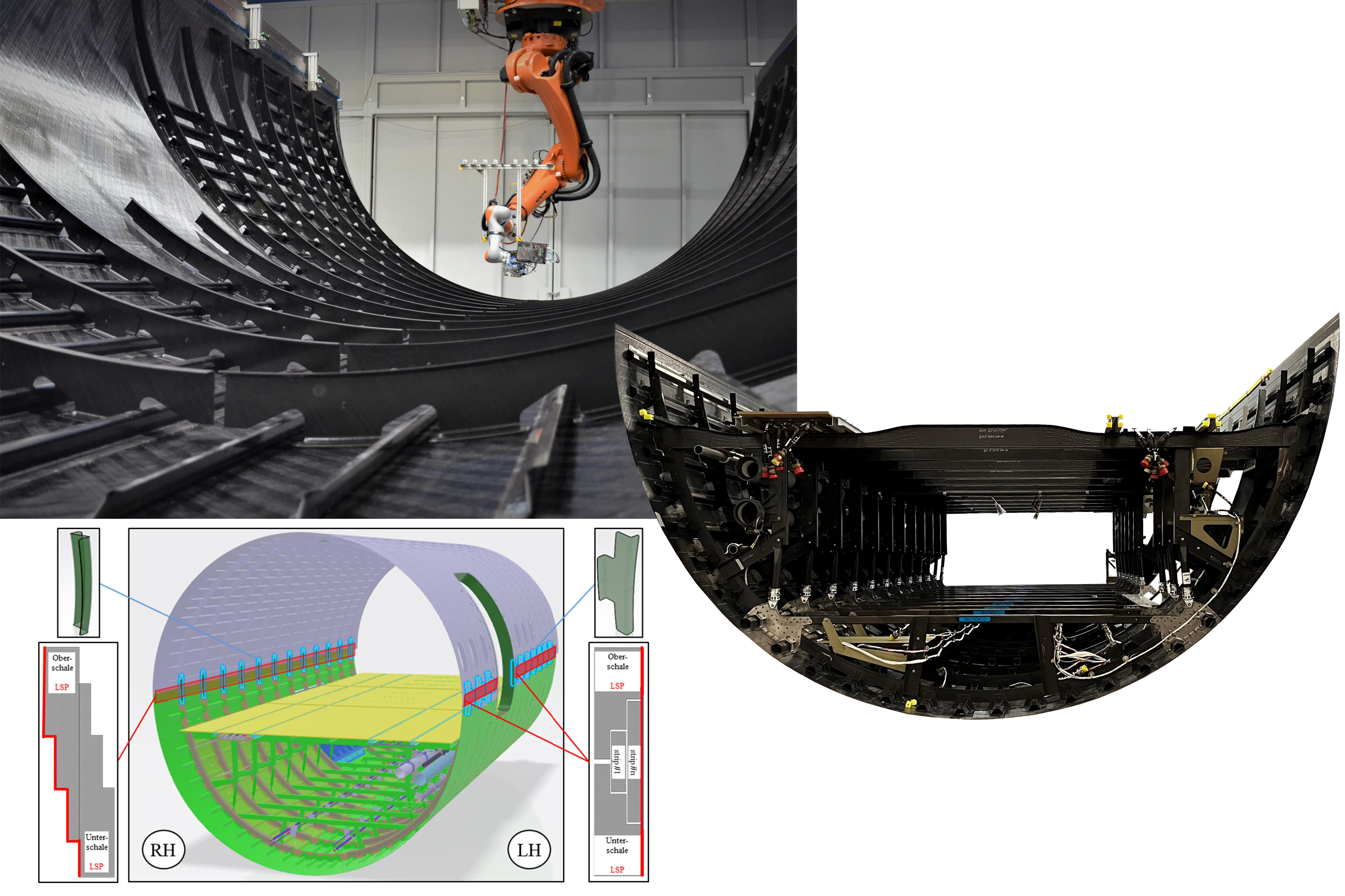
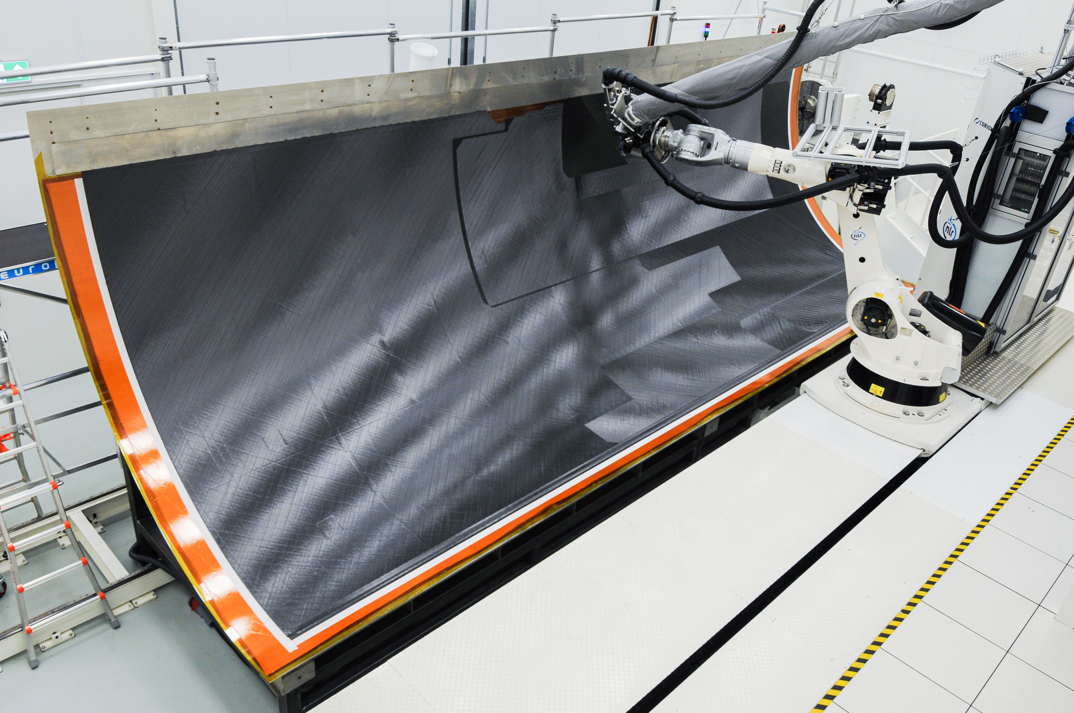
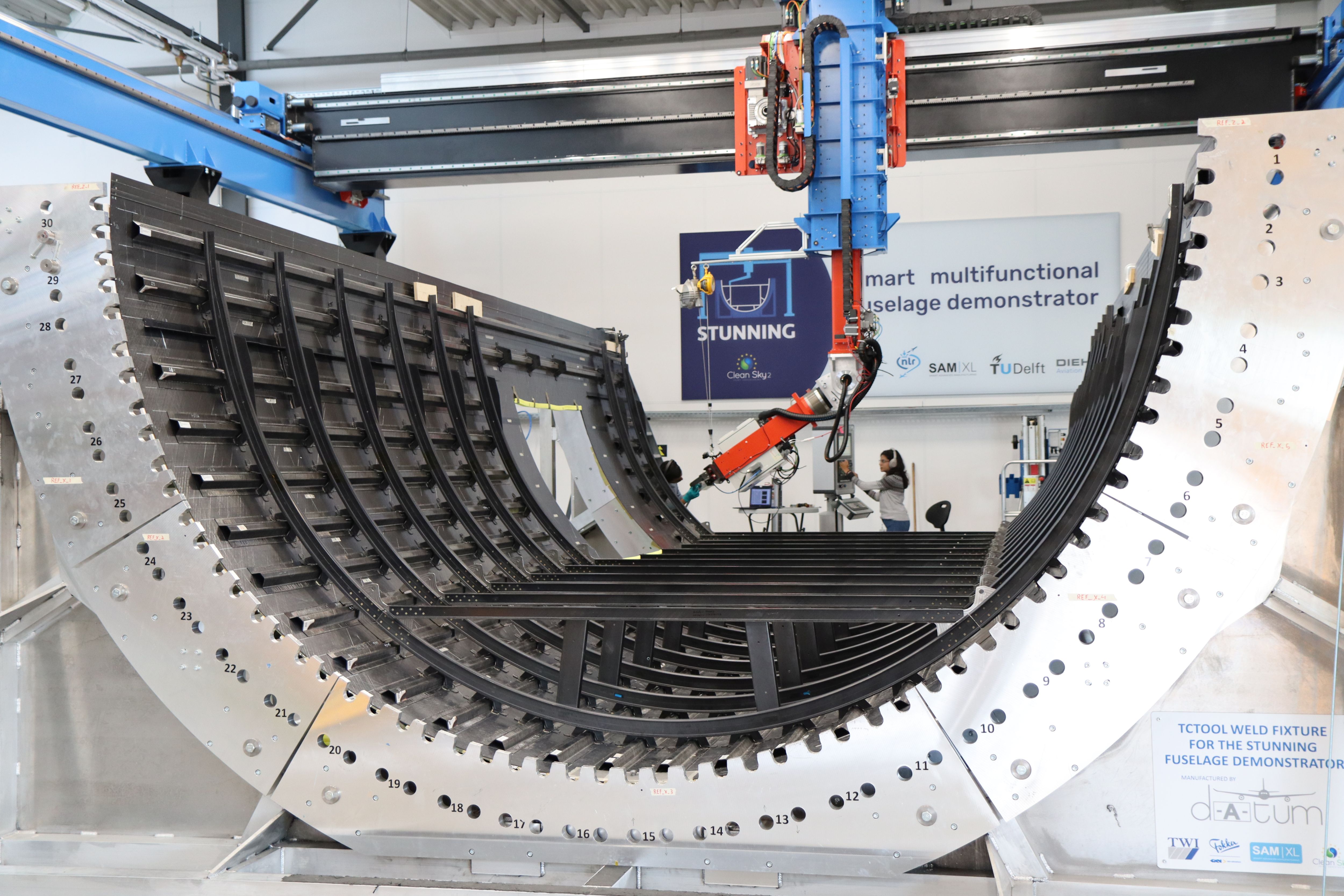
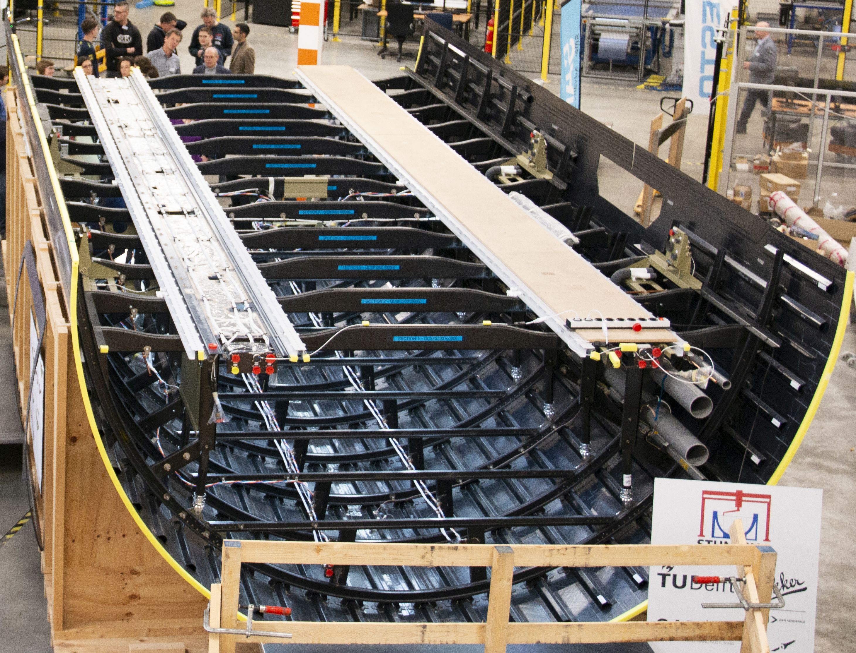
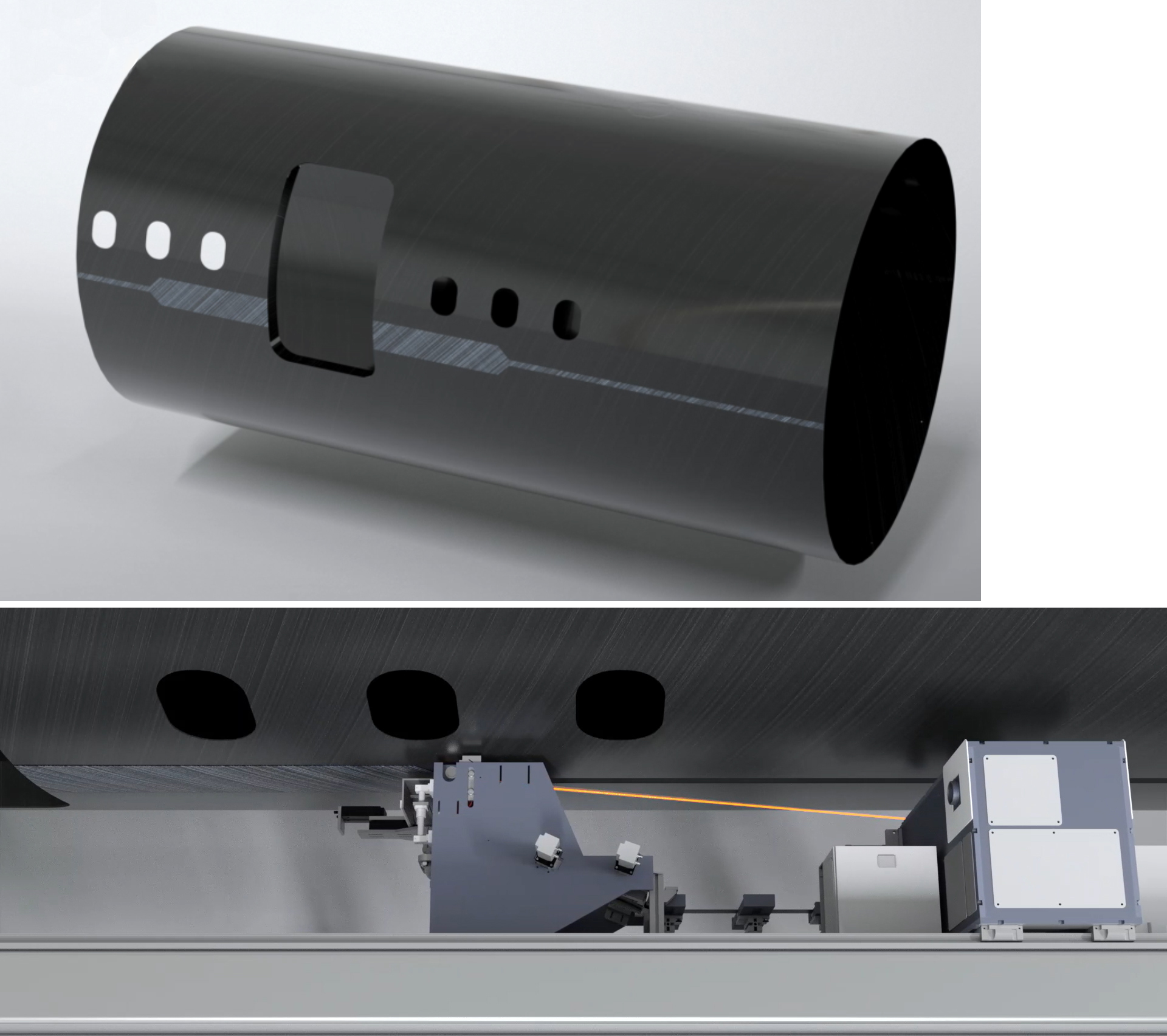
AFP in-situ consolidation, welded assembly. Stringers, frames and clips are welded to the AFP in-situ consolidated skin of the MFFD upper shell (top left) which will be welded to the completed lower shell (right) using two different longitudinal fuselage joints (bottom left). Photo Credit: DLR CC-BY license, Fraunhofer IWS, GKN Fokker. Photo Credit all images: Clean Sky 2/Clean Aviation
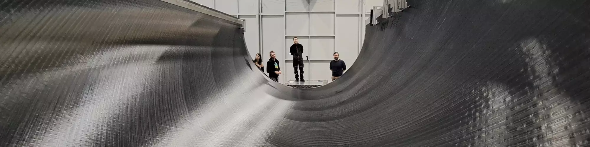
Landscape photo: In-situ consolidated skin of the MFFD upper shell. Photo Credit: DLR CC-BY license
The Multifunctional Fuselage Demonstrator (MFFD) program was conceived in 2014 as one of three large aircraft demonstrators within the EU-funded Clean Sky 2 (CS2) initiative (now Clean Aviation) aimed at advancing innovative technologies, aircraft sustainability and a competitive supply chain in Europe. When disseminated in 2017, the MFFD program goals were ambitious: Build an 8-meter-long, 4-meter-diameter fuselage section fully from carbon fiber-reinforced thermoplastic polymer (CFRTP) composites to enable production of 60-100 aircraft/month with a 10% reduction in fuselage weight and 20% cut in recurring cost. By the project’s end in 2024, overall technology readiness level (TRL) for such a fuselage will be advanced to TRL 5.
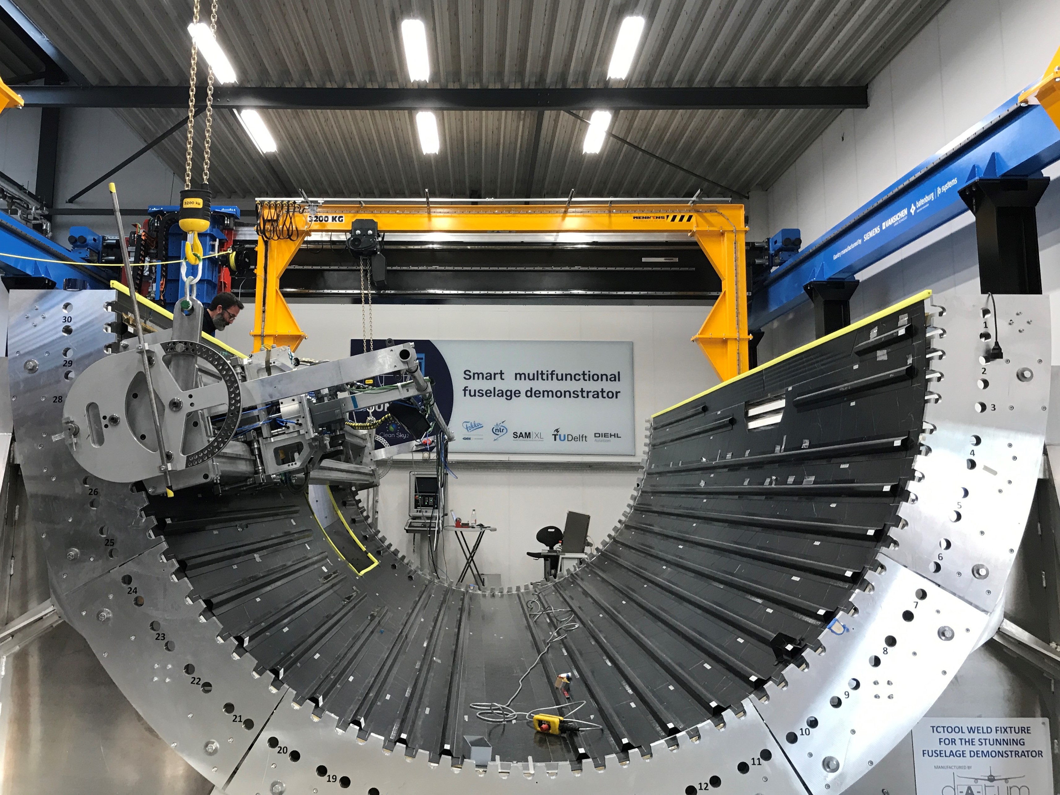
From 2017-2019, Airbus Research & Technology (Bremen, Germany), as the MFFD project leader, issued 13 CS2 calls for proposal CfP07–CfP11 for work topics such as automated assembly plant for a thermoplastic fuselage, micromechanics of welded joints, novel tooling, multifunctional pick-and-place/welding end effectors, new test methods and testing, longitudinal fuselage joints, digital twins, CFRTP fuselage repair and more. The consortia that responded were awarded hundreds of work packages, completed by more than 40 companies and organizations (Fig. 1). “This multidisciplinary and international collaboration is the only way we will reach climate-neutral aviation by 2050,” says Salvador Romero Esteban, principal R&D engineer at GKN Fokker (Hoogeveen, Netherlands).


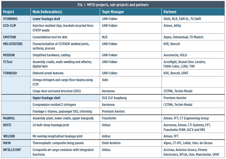
Photo Credit: Clean Sky 2/Clean Aviation
MFFD’s completed lower shell has been shipped to Fraunhofer Institute for Manufacturing Technology and Advanced Materials (IFAM, Stade, Germany) for final assembly, and the upper shell should arrive by late July. “Setup of the lower and upper shells in the assembly fixture should take 1-2 months,” says Eric Pohl, research associate at Fraunhofer Institute for Material and Beam Technology (IWS, Dresden, Germany) in the BUSTI project. “We should be able to start welding the left-hand [LH] side butt-strap joint via laser in-situ joining by the end of August/start of September.” The right-hand (RH) overlap joint will then be completed by Aimen Centro Tecnológico (Porriño, Spain) and FFT (Fulda, Germany) via ultrasonic welding, followed by final evaluation of the MFFD digital twin (see last section of “Proving out LMPAEK welding for MFFD”).
The goal of this article is to give an overview of the MFFD manufacturing steps completed so far and a discussion of the laser-based co-consolidation process that will be used for the LH side butt-strap joint.
Within STUNNING, material testing and computer models were used to predict distortion during AFP, transport and consolidation, especially through the many ramp zones near the passenger door cutout. Photo Credit: Fig. 4, “Development of a MultiFunctional Fuselage Demonstrator” by Veldman, et. al, Feb. 2020.
Note, the short length of the lower shell summary below belies its complexity — each sentence represents numerous reports regarding key developments in novel tooling, multifunctional end effectors, physics-based models, process simulation, welding lessons learned and more. The methodology and systems for automated assembly of the lower shell alone could be its own article (see 2021 technical paper by S.L. Omairey, et. al). Although there isn’t room for such detail here, stay tuned for future CW articles on the MFFD and the technologies it has developed.
Lower shell skin
Step 1. AFP layup of lower shell skin was completed in two halves. Photo Credit: STUNNING project, NLR
Netherlands Aerospace Centre (NLR, Marknesse, Netherlands) used a Coriolis Composites (Quéven, France) C1 robotic automated fiber placement (AFP) system for fast layup (versus AFP in-situ consolidation) of two subsequent 90° fuselage segments on a single layup tool at room temperature (Step 1). The single quadrant size was dictated by the reach of the AFP machine. Including lightning strike protection (LSP) material in the outer plies, the layups were designed to form a scarf/taper joint at the keel and used Toray Advanced Composites (Nijverdal, Netherlands) TC1225 unidirectional (UD) tape comprising T700 carbon fiber (CF) and Victrex (Lancashire, U.K.) low-melt polyaryletherketone (LMPAEK). Note: Unless otherwise stated, all CFRTP components in the MFFD were made from TC1225 UD tape.
Step 2. Two halves were integrated via scarf joint at keel and co-consolidated in autoclave. Photo Credit: STUNNING project, EMOTION project, NLR
The skins and keel joint were co-consolidated by the NLR team in an innovative, high-temperature consolidation mold (produced by the EMOTION subproject) in a research autoclave at the German Aerospace Center (DLR) in Stade, Germany (Step 2). NLR used thermography as a fast nondestructive inspection (NDI) method to scan the resulting 180° entire lower fuselage skin in just over 2 hours. The NDI showed an aerospace-quality laminate, confirmed by local C-scans and cross-sectioning. The skin was then shipped to partner SAM XL (Delft, Netherlands) for integration of structures and interior systems.
Welded stringers, frames, subassemblies
Step 3. Continuous compression molding (CCM) omega stringers were conduction welded to the lower shell skin, supported in the cradle tool. Photo Credit: STUNNING project, GKN Fokker

Step 4. Injection molded clips were ultrasonic welded to omega stringers and to skin. Photo Credit: STUNNING project, SAM XL
The skin was positioned in a cradle tool — equipped with 34 backing anvils to support a variety of welding processes — developed by the TCTool subproject. Omega stringers produced by Xelis (Herford, Germany) using continuous compression molding (CCM) were conduction welded by GKN Fokker to the skin (Step 3) using a 1-meter-long welding end effector. Subsequent ultrasonic welding of clips to the stringers and skin was carried out by SAM XL in collaboration with TU Delft using a 16-millimeter end effector (Step 4, further described in “Thermoplastic composites welding advances for more sustainable airframes”).
Step 5. Frames were co-consolidated from flat preforms using an Invar tool in the autoclave. Web width tapered at outer ends of RH and LH frames. Photo Credit: GKN Fokker
GKN Fokker produced 12 sets of three (RH, central and LH) curved fuselage frames using its “butt joint” technology (see “Orthogrid” section in “Thermoplastic primary aerostructures …”), which co-consolidated one flat web preform and two flat flange preforms with noodle fillers in a grooved Invar tool in the autoclave (Step 5). “Because our frames don’t have feet,” explains Romero Esteban, “we extend the web preform beyond the flanges to create space for the noodles and also for welding the floor beams during shell assembly.” After consolidation — which in the future will be in a heated press — the curved webs were trimmed.
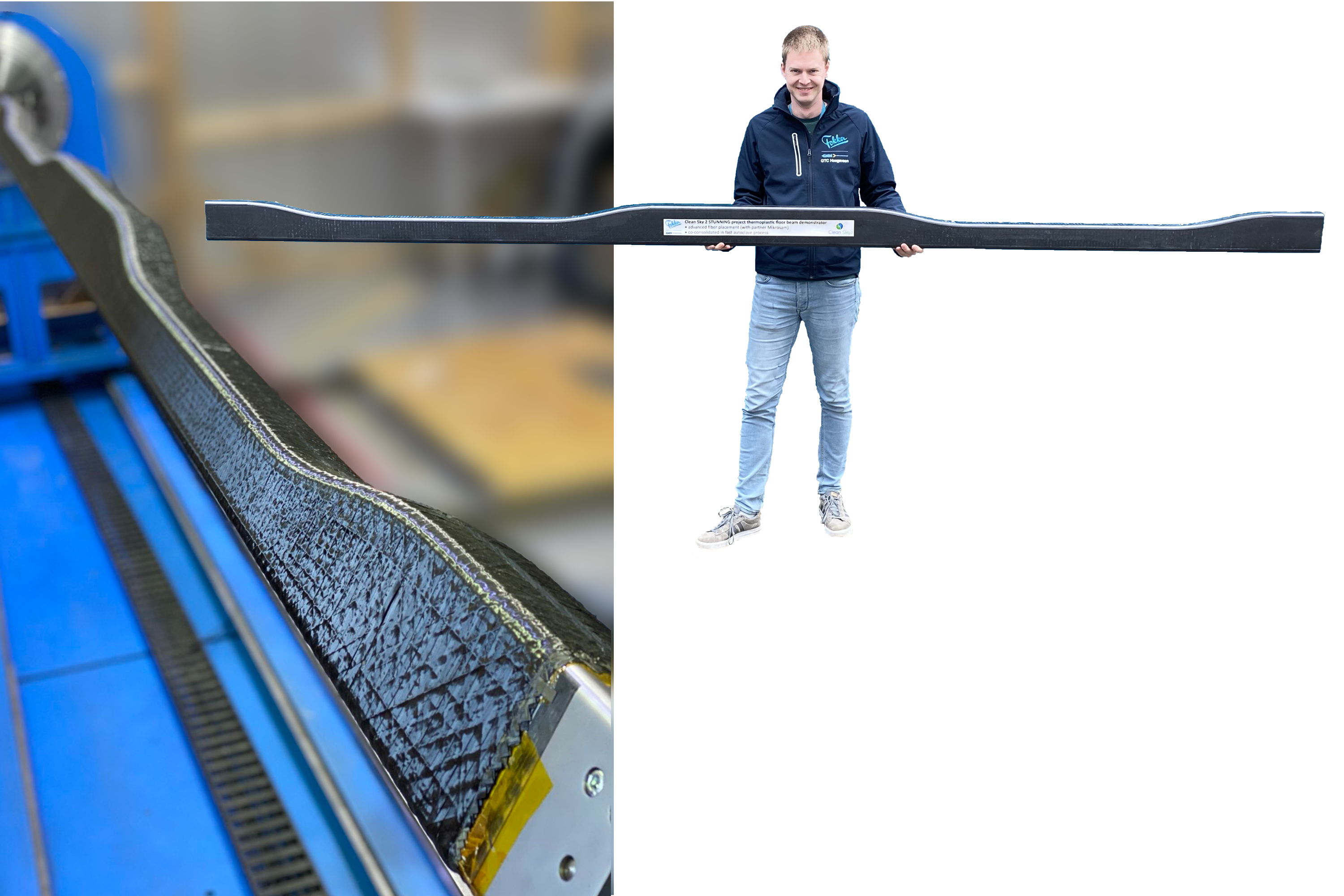
Step 6. Passenger floor beams were made using AFP and autoclave consolidation. Photo Credit: STUNNING project, GKN Fokker
GKN Fokker also fabricated the passenger floor beams, using a Mikrosam (Prilep, Macedonia) robotic AFP system and tow steering onto a shaped steel mandrel (Step 6). As described in “MFFD thermoplastic floor beams,” each layup was split to produce two floor beam preforms which were then consolidated in an autoclave. The finished floor beams were then welded into assemblies, described next.
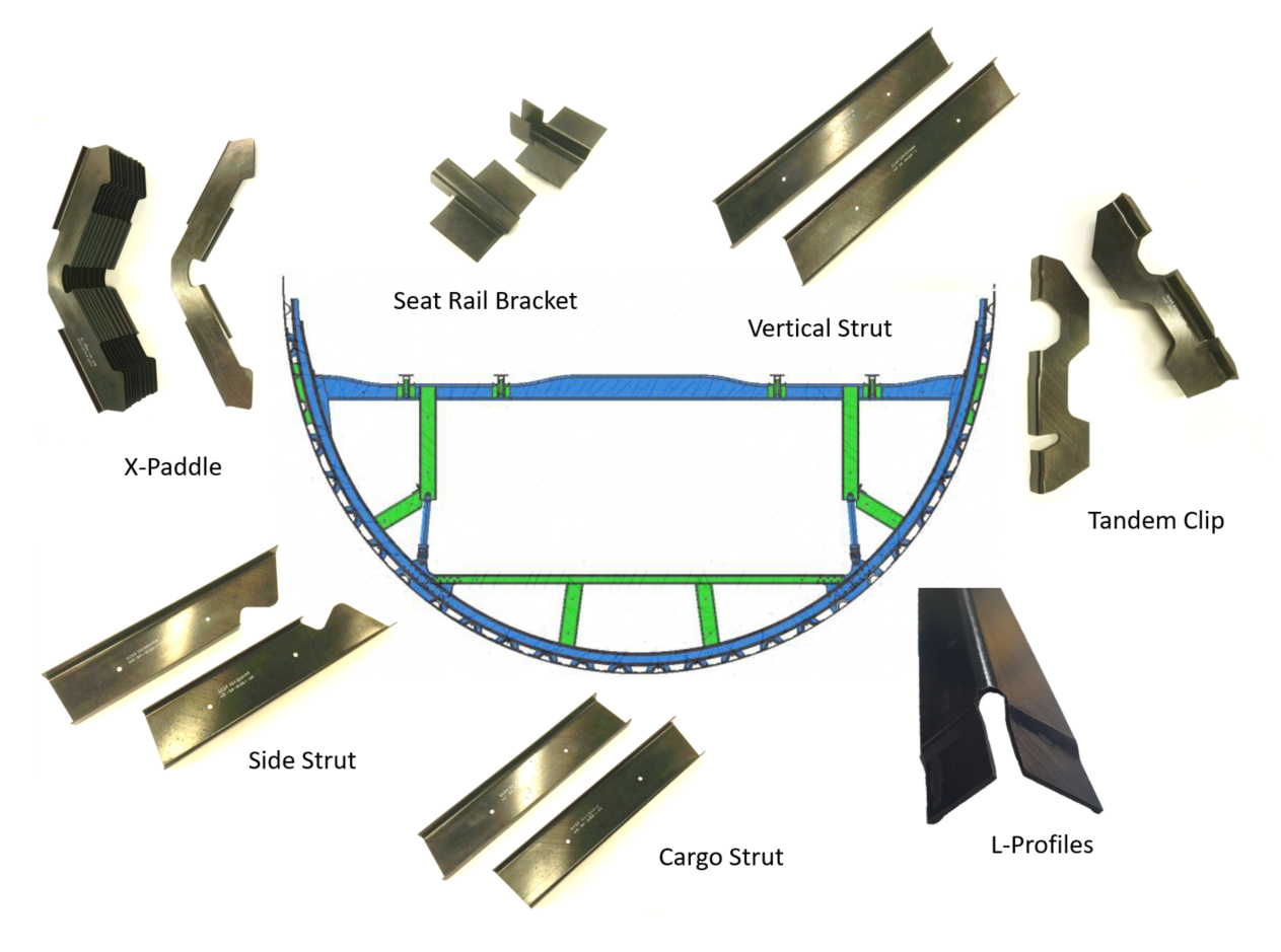
Step 7. Additional parts for frame and floor subassemblies were stamped and then conduction welded to frames and floor beams. Photo Credit: STUNNING project, GKN Fokker
To provide support for cargo and passenger floors, GKN Fokker manufactured more than 100 struts, profiles and other attachment structures — in seven different geometries — using stamp forming. It then conduction welded these to each other and the curved fuselage frames to create the frame subassemblies and to the floor beams to create the floor beam subassemblies (Step 7). At SAM XL, the frame subassemblies were then ultrasonic welded to the eco-clips (Step 8).
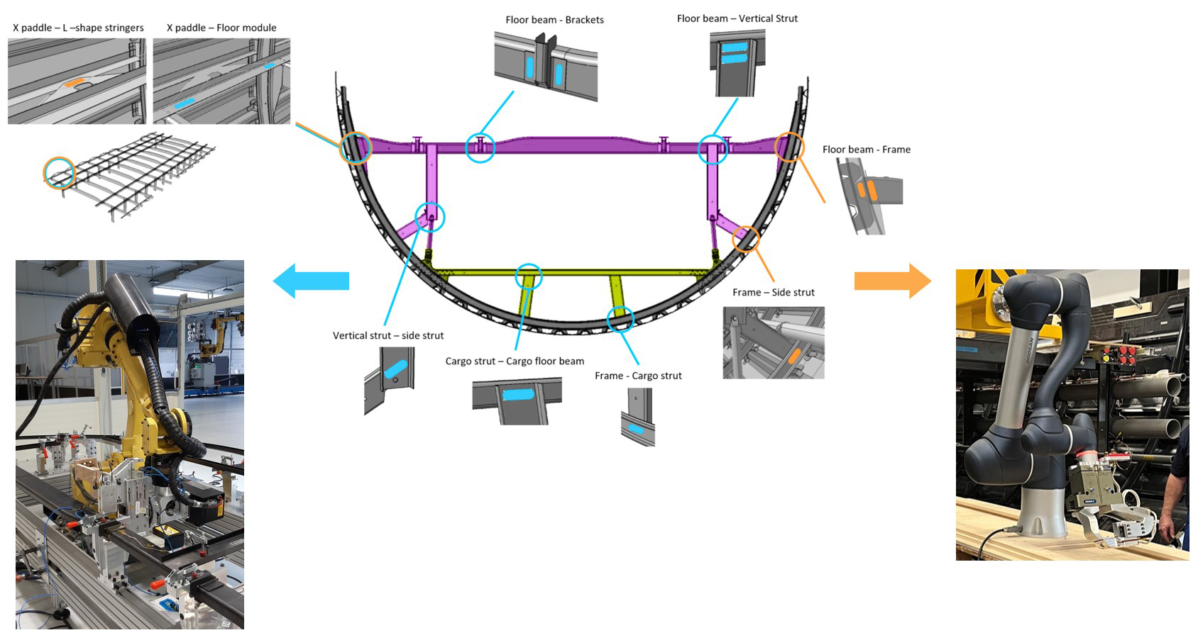
Figure 2. Conduction welding lower shell subassemblies. Frame sub-assemblies (yellow) and floor beam subassemblies (purple) were welded by GKN Fokker using its robotic conduction welding system at the GKN Aerospace Global Technology Centre Netherlands in Hoogeveen (blue). SAM XL robotically ultrasonic welded frame subassemblies to the lower shell (blue). GKN Fokker conduction welded floor beam subassemblies to the shell using GKN’s new welding head with heated rod element and anvil for counterpressure (orange). Photo Credit: STUNNING project, GKN Fokker.
Step 8. Frame subassemblies were ultrasonic welded to eco-clips. Photo Credit: STUNNING project, SAM XL
Step 9. Finished MFFD lower fuselage with conduction welded floor beam subassemblies and integrated seat track, electrical and HVAC system components. Photo Credit: STUNNING project, SAM XL
In parallel, the 12 floor beam assemblies were then joined with the floor grid substructure — including two aluminum seat tracks, electrical systems developed in the MISSION project and air system conduits — as part of MFFD’s mandate to demonstrate welded assembly of pre-equipped fuselage shell modules. The final step was to weld the floor grid structure to the frames and lower shell using GKN Fokker’s patented new conduction welding process that comprises a heated rod element with an anvil for counterpressure (Fig. 2) — completing more than 800 joints and 500 meters of welding (Step 9).
In-situ consolidated upper shell skin
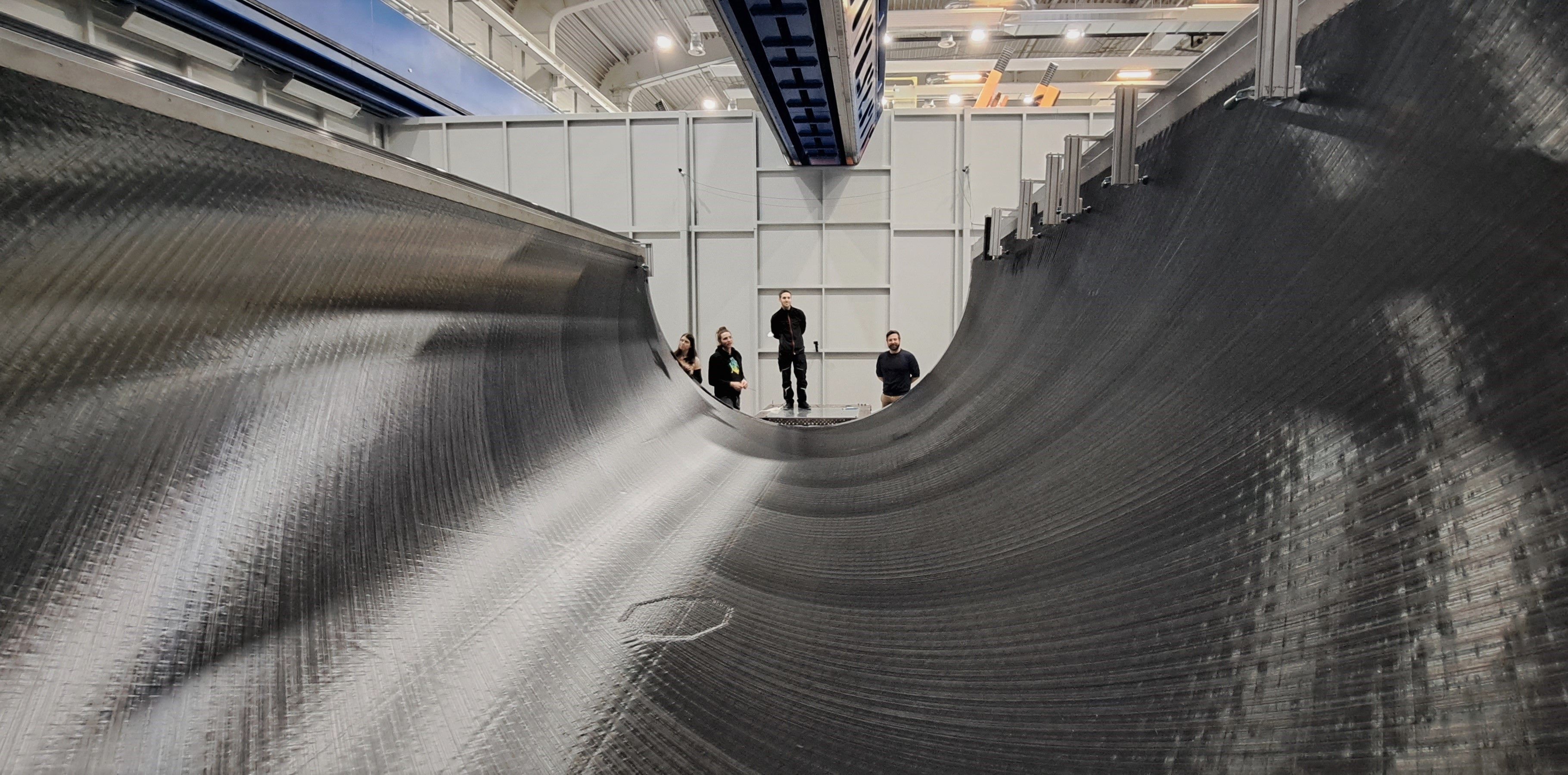
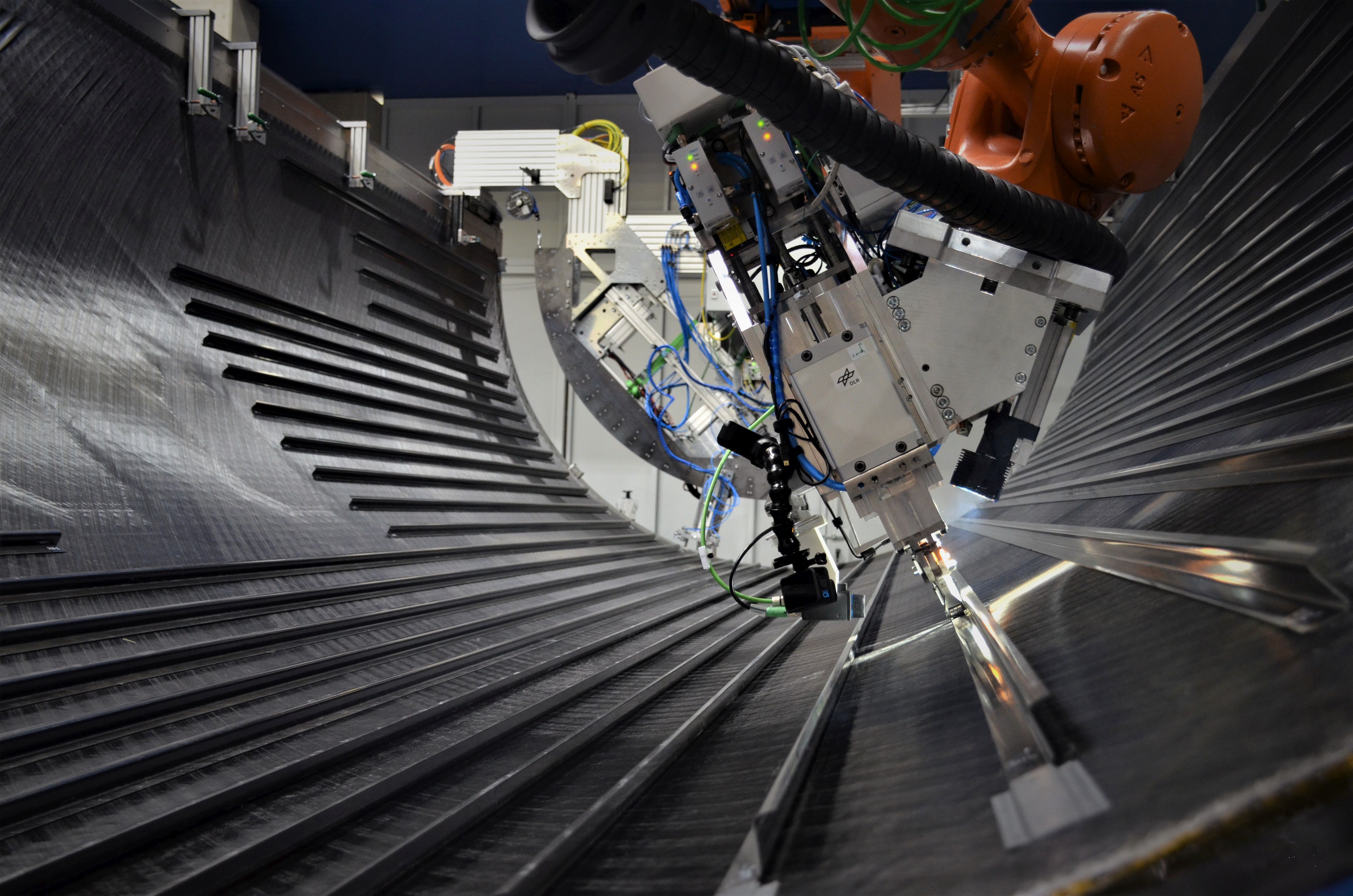
Step 10. AFP in-situ consolidation of upper shell skin. Photo Credit: DLR CC-BY license
The skin for the MFFD upper shell was produced by the DLR Institute of Structures and Design Center for Lightweight Production Technology (ZLP, Augsburg), using AFP in-situ consolidation (see “Consolidating thermoplastic aerostructures in place, Part 1 and Part 2). In this process, the TC1225 UD tape is fully consolidated as it is applied, in one step, without further vacuum bagging, oven or autoclave (Step 10). “This reduces panel lead time by up to 40% compared to a typical A350 fuselage panel using thermoset epoxy,” says Frederic Fischer, DLR project manager for the upper shell. “However, the process is more demanding because you don’t have a second consolidation step.”
“For example,” explains Dominik Deden, DLR research engineer responsible for the upper shell AFP skin production, “you can’t have gaps and overlaps in the applied tapes because those will become voids in the structure. They will also lead to a rough surface in each ply and negatively affect the thermal control. For this reason, the path planning must be adapted to the respective AFP parameters to ensure adequate laminate quality.”
ZLP developed an inline inspection system especially for the in-situ process. “We have a system of sensors on the AFP end effector that logs gaps and overlaps during production,” says Lars Brandt, DLR’s expert on AFP and advancement of in-situ process control. He notes there is a huge interdependency between the process parameters: “They directly affect the thickness and width of the tape, which then affects how the tapes lie properly next to each other, and in turn, the thermal imaging for the closed-loop control of the laser power. So, we must make sure we have the best temperature, pressure and speed of the robot end effector at all times.”
DLR conducted extensive simulation and parametric trials to establish the required process window for best part quality and high deposition rates. It in-situ consolidated a full-scale test shell skin with more than 70 plies of tape and analyzed the collected sensor and process data. “From this, we have developed optimal time-temperature curves and compared with mechanical properties of the laminate, such as interlaminar shear strength [ILSS],” says Brandt. “Due to the complex interplay of the process parameters, the work still continues, but we aim to have a definitive assessment of the in-situ quality before the end of the year.”
For the final MFFD upper shell, DLR completed the in-situ consolidated skin in February 2023, using a multi-tow AFP head from AFPT (Dörth, Germany) with a Laserline (Mülheim-Kärlich, Germany) LDM diode laser for heating and a layup tool supplied by Grunewald GmbH & Co. KG (Bocholt, Germany). The AFP end effector can place three 0.5-inch-wide tows with a possible throughput up to 4.4 kilograms/hour for a minimum production time of 32 hours. “The number of tows could easily be increased for faster layup and production rates of 70 to 100 aircraft per month,” says Deden. The upper shell skin also included LSP film as the first ply.
Welded stringers, C-frames, cleats
Step 11. Compression molded Z-stringers joined to skin using continuous ultrasonic welding. Photo Credit: DLR CC-BY license
Z-stringers for the upper shell were supplied by Aernnova (Miñano, Spain) made in collaboration with CETMA (Brindisi, Italy) using its CCM process (see “CETMA R&D” and “Leonardo and CETMA”). DLR used ultrasonic spot welding to integrate energy directors — an extra layer of unreinforced LMPAEK resin along each stringer foot — which helps to control energy at the weld interface (see “MFFD upper half” section in 2022 welding article). The same robotic end effector, with minor modifications, was also used for the continuous process to integrate the 46 Z-stringers to the skin (Step 11).
“This was the world’s first stringer welding on in-situ consolidated skins by fully automatic continuous ultrasonic welding using camera-based path correction at 1.4 meters/minute,” says Fischer. “We were able to demonstrate a reproducible weld strength of 38 megapascals in coupon testing.”
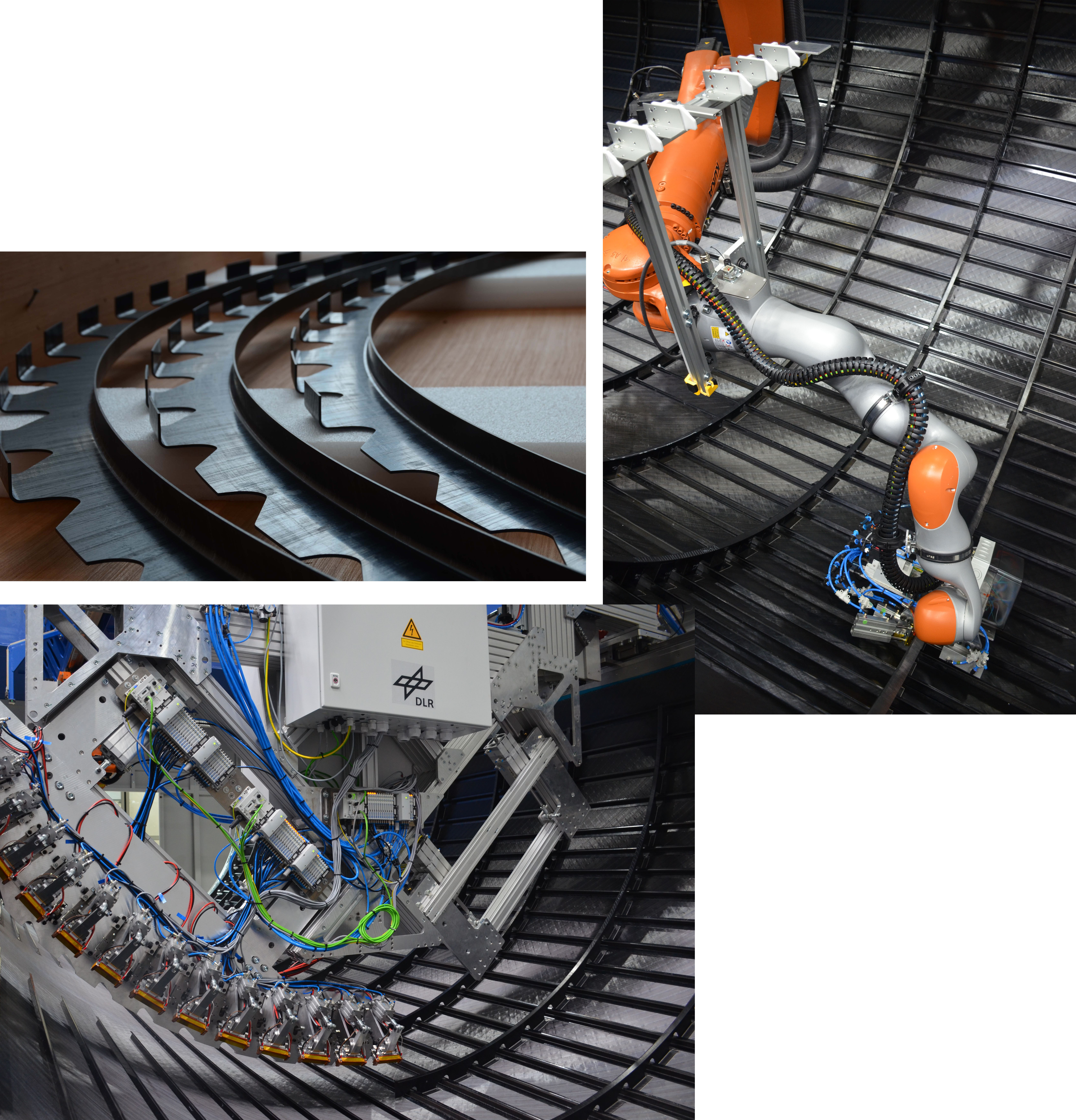
Step 12. Resistance welding bridge joined compression molded C-frames to skin, then cobot-on-robot (top right) resistance welded cleats as shear ties between stringers and frames. Photo Credit: DLR CC-BY license
Next, 24 one-shot, press-molded C-frames produced by Premium Aerotec (PAG, Augsburg and Bremen, Germany) were resistance welded to the upper shell skin using a weld bridge developed by DLR (Step 12). The motor-driven bridge is mounted on the upper side of the layup tool and is able to automatically transport and position the frames to their precise integration positions on the shell skin. The bridge contains 14 weld modules that sequentially apply up to 1.2 megapascals of pressure to each foot along the C-frame (see “MFFD upper half” section in 2022 welding article).
“The modules then apply electric current into a welding element positioned between each frame foot and the skin,” says Manuel Endrass, DLR expert for resistance welding. The welding elements were made from Toray CETEX TC1225 prepreg with T300JB carbon fiber in a 5-harness satin fabric — the same LMPAEK matrix as in the UD tape skin — and CETEX TC1225 EC5 E-glass 4-harness satin prepreg. The latter is used to prevent a short circuit where fiber orientation of the welded parts and the welding element is aligned. The electric current flows through the welding elements and creates heat that melts the matrix in the weld interface. Once the current flow is switched off, the weld cools while pressure is maintained. “We demonstrated the scalability to weld an entire frame in 5 minutes,” says Fischer. “This robust technology gives full-surface connection with a weld strength equal to that of the press-consolidated reference. In essence, our resistance welding can be understood as a miniaturized pressing process.”
After the frames, DLR again used resistance welding to integrate cleats as shear ties between the Z-stringers and curved fuselage frames (Step 12). “DLR developed a cobot-on-robot-based welding system to fit in the highly confined space,” explains Endrass. “The idea behind this development was to automatically integrate the cleats without knowing the exact as-built conditions. Thus, the LBR iiwa cobot [KUKA Robotics, Augsburg, Germany] with its compliance-controlled steering capabilities will self-align without any preliminary part measurement or robot teaching. Since the weld force is applied by a closed-force flux design of the end effector, it is possible to integrate the cleats without introducing external loads.” DLR plans to deliver the upper shell to Fraunhofer IFAM by end of July. However, its work on resistance welding and in-situ consolidation will continue.
LH longitudinal fuselage joint
Step 13. Advanced laser in-situ joining will be used to co-consolidate a six butt-strap laminates to fuselage shells, creating the LH longitudinal fuselage joint. Photo Credit: BUSTI project, Fraunhofer IWS
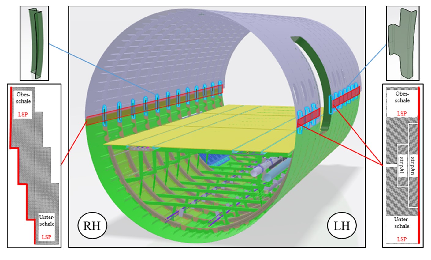
Step 14. RH overlap fuselage joint will be created by continuous ultrasonic welding. Resistance-welded frame couplings (top corners) will connect upper and lower frames and skins. Photo Credit: BUSTI project, Fraunhofer IWS
Assembly of the MFFD lower and upper shells will begin with the LH side butt-strap longitudinal fuselage joint, which has been developed within the BUSTI project (Step 13). Led by Airbus, it includes partner Aernnova, Aimen, CTI Systems (Lentzweiler, Luxembourg), FFT and Fraunhofer IFAM, IGCV and IWS. The RH overlap fuselage joint will be completed using ultrasonic welding by FFT and Aimen through the WELDER project (Step 14). The assembly fixture, which will hold the lower and upper shells together during the joining processes, was developed within the MultiFAL project and includes the cradle for the lower shell and a system of 10 cooperating hexapods for locating and adjusting the position of the upper shell. Vacuum grippers with six-axis force and torque sensors will adjust the pose and shape of the shells, guided by optical measuring systems, to manage tolerances during assembly.
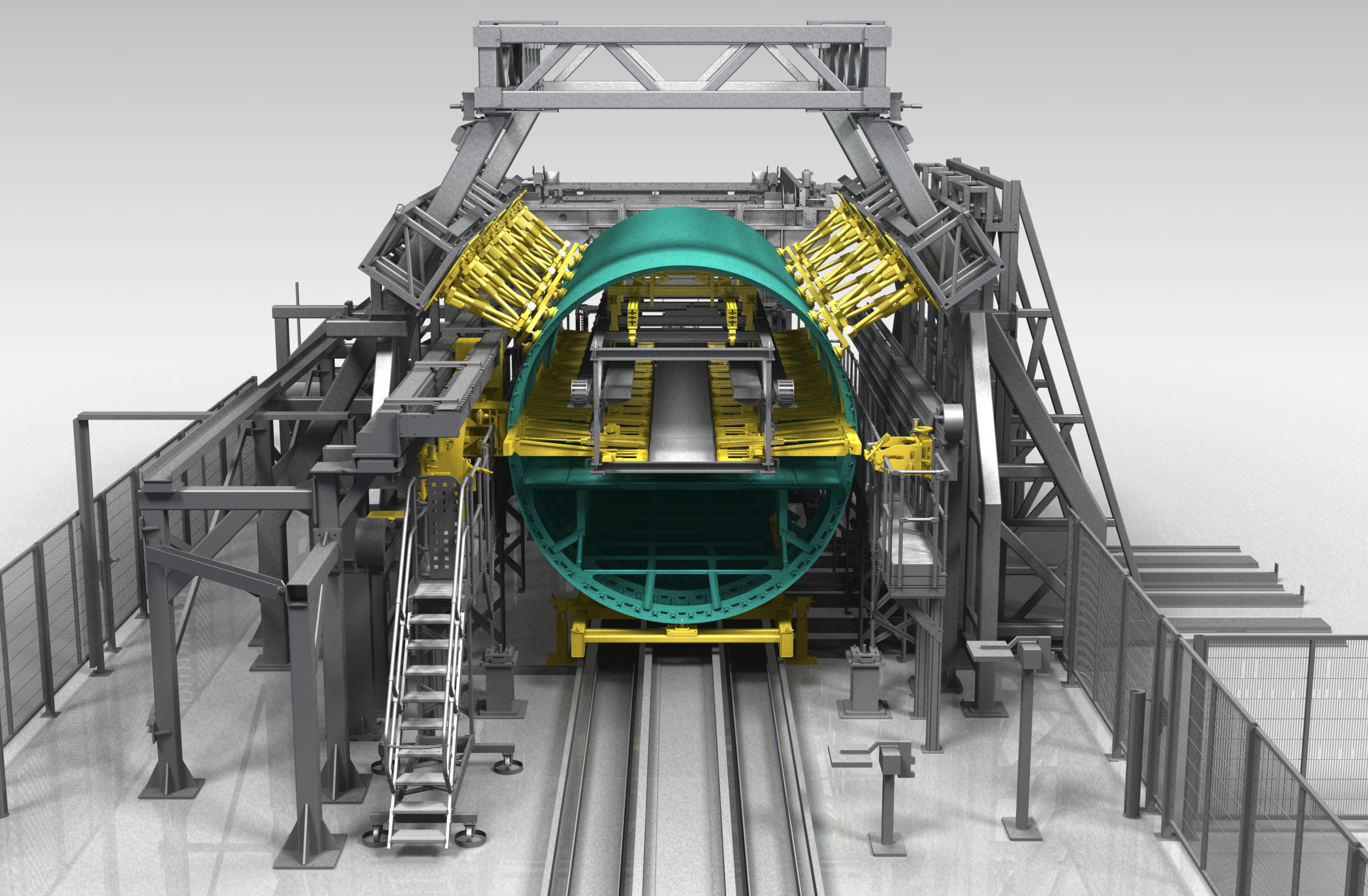
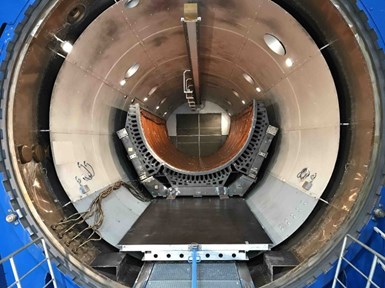
Assembly fixture. Developed in the MultiFAL project for assembling MFFD fuselage shells, the fixture includes a cradle for the lower shell and cooperating hexapods (yellow, top of fuselage) to adjust the shells for joining. Photo Credit: MultiFAL project, Fraunhofer IFAM
The lower shell is placed first, followed by the upper shell. The hexapods will adjust the shells to the correct geometry for the joining processes. Inside the fuselage, large aluminum blocks (“inner positioners”) curved to match the fuselage will press outward in the radial direction to resist the consolidation pressure applied by welding end effectors during joining.
For the BUSTI project and LH butt strap joint, Fraunhofer IWS has developed a process called laser in-situ joining (CONTIjoin for continuous joining), explains Pohl, “but it is actually continuous co-consolidation of the CFRTP butt strap laminates to the mated fuselage shells.” In contrast to adhesively bonded joints, no pretreatment of the join area is required other than to make sure the surface is clean from machining dust, etc. “It’s very similar to the AFP consolidation process,” he says. “No further post-processing is needed, but instead of applying a single ply of tape, we use 6-ply, fully consolidated laminates.”
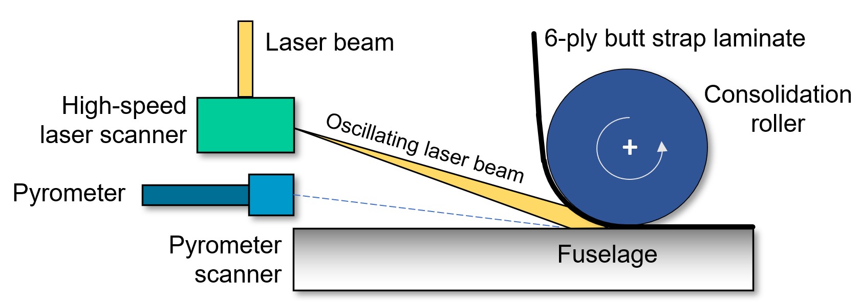
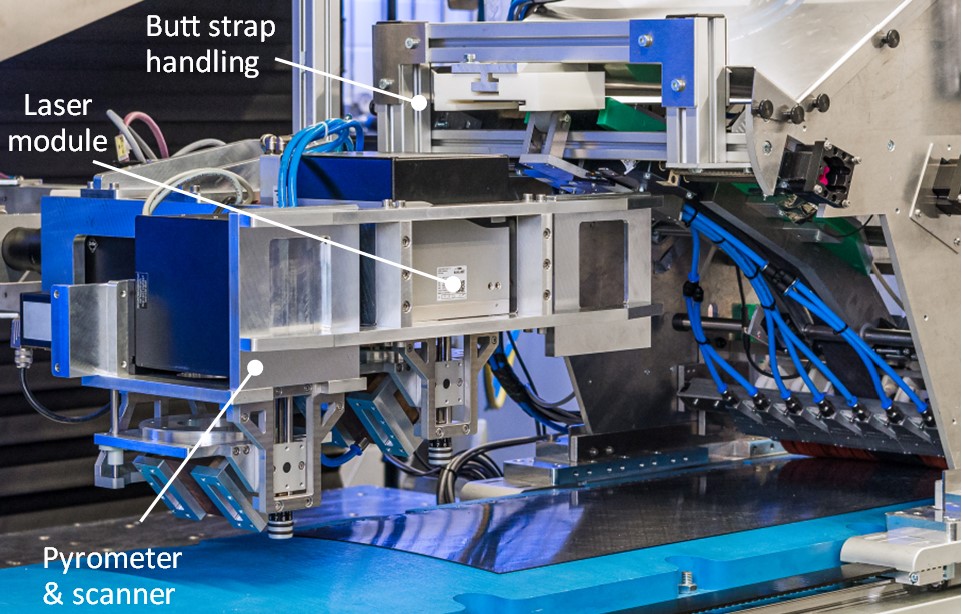
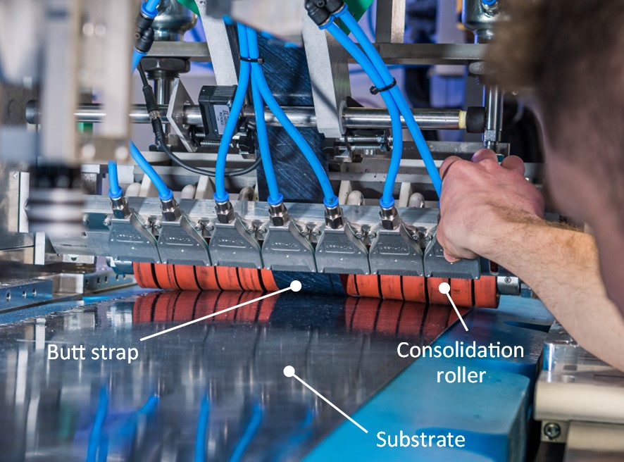
Figure 3. Laser in-situ joining (CONTIjoin) process. This Fraunhofer IWS lab setup shows how the 6-ply butt strap laminates will be brought in and applied to the joint area, heated by the oscillating laser beam and, with pressure from the consolidation roller, will be co-consolidated with the substrate upon cooling. Photo Credit: BUSTI project, Fraunhofer IWS
“We also use a CO2 laser instead of the fiber lasers typical for AFP,” continues Pohl. “This is because LMPAEK polymer shows almost no energy absorption at the 1,060-nanometer wavelengths normally used by those lasers. Because we need sufficient absorption to melt the surface matrix for joining, we use a CO2 laser with a 10.6-micrometer wavelength to ensure better heating of the polymer matrix at the surface with less migration through the laminate plies.”
Because the butt strap laminates get progressively wider from the first at 60 millimeters to the final at 360 millimeters, the CO2 laser is combined with a high-speed scanning system that oscillates the energy beam across the width of the weld. The laser beam alone can’t span the width of the butt straps, says Pohl, but also, the laser beam’s energy intensity is at its center and decreases outside the laser focus spot. It’s the highly dynamic beam oscillation that enables heating across the entire width of the joint, up to 360 millimeters.
Temperature control
The CONTIjoin process equipment uses two optics setups. One is the oscillating laser and the other comprises a pyrometer and a second scanner for measuring temperature along the join (Fig. 3). “The pyrometer is targeted at the nip point and used to adjust the laser power to maintain the required process temperature (350-370°C),” explains Pohl. However, that nip point is actually a line that spans the butt strap width. “So, we combine the pyrometer with a high-speed scanner so we can adjust the target for where the pyrometer measures,” he adds.
“The oscillating laser beam heats the surface of the join area,” continues Pohl, “and the scanning pyrometer setup measures the temperature at different points that we set, based on the width of the butt strap laminate. We found that using one point in the middle of laminates up to 60 millimeters wide is enough to control the process homogenously. For wider laminates, we need to add a measuring point for each 60-millimeter increase. So, for the second step laminate, which is 120 millimeters wide, we use two pyrometer spots, and we use four spots for the 240-millimeter-wide strap, etc.” The pyrometer jumps through these measuring points, per its digital control system, where both distance and timing can be set individually. Pohl notes, “In this context, the synchronization of the individual processes with each other is crucial for the resulting co-consolidation quality.”
The temperature information from each measurement feeds an individual control circuit to adjust the laser power for that point. “Let’s say we have a 350°C set temperature and the pyrometer measures 340°C,” says Pohl. “This is then fed into a proportional integral derivative [PID] control loop. The PID controller recognizes it’s less than the set temperature and increases the laser power. The amount of that increase has been established earlier through process parameter trials and is programmed into the PID.”
Applying the butt strap laminates
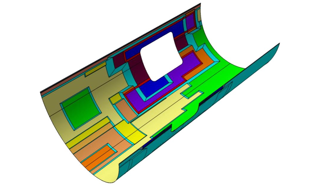
As discussed above, the butt strap comprises six progressively wider straps, applied one at a time. This matches a set of steps built into the upper and lower shells where they meet. Airbus calls this a step joint structure, which is also used in bonded and welded repairs of composite aircraft structures. Thus, the area where the butt strap will be welded fits precisely into a stepped area to receive it. “This is a good design for joining these shells,” says Pohl, “because you are co-consolidating or welding into the thickness of the material, so you get more surface area in all layers of the joint.”
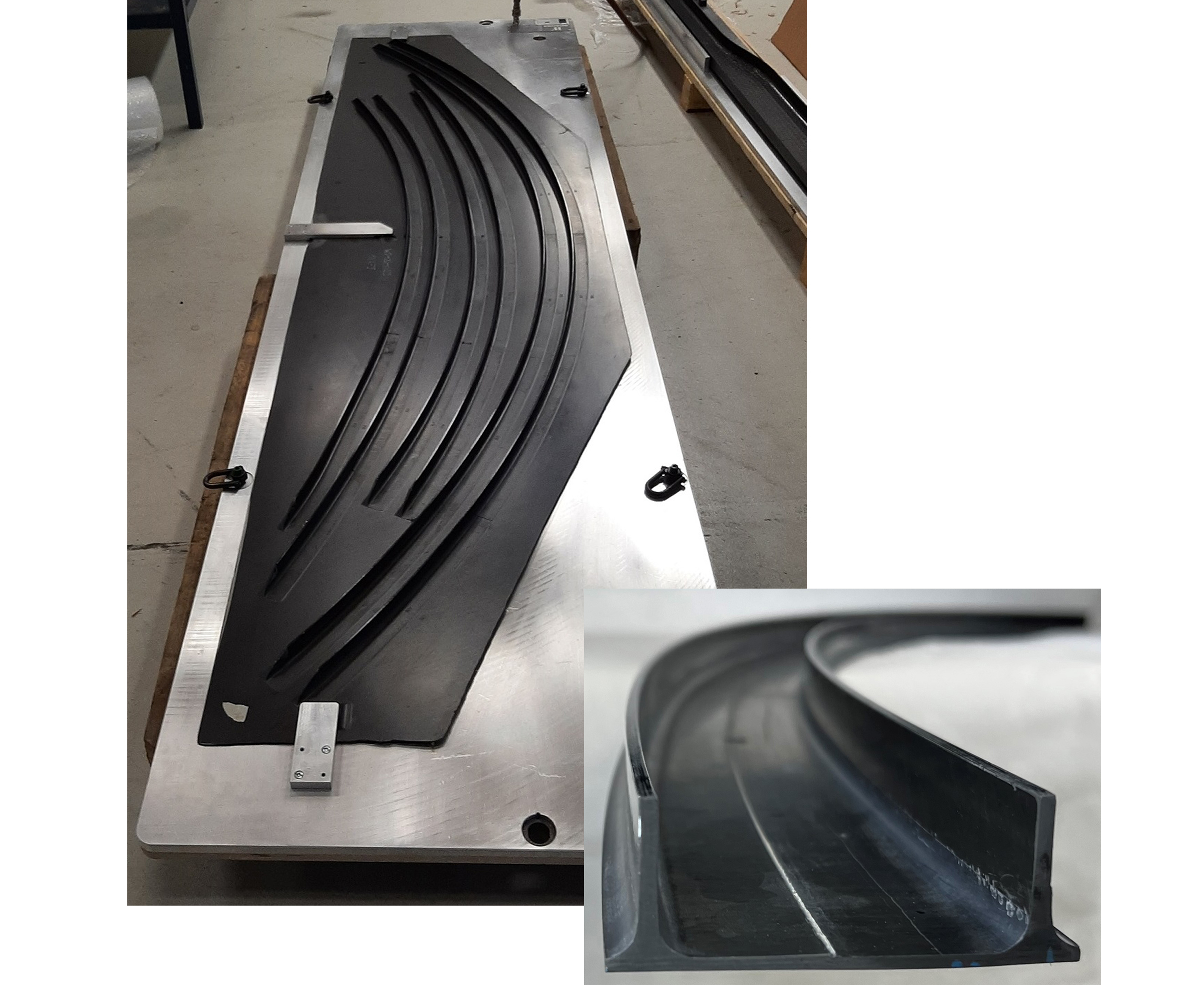
Pohl’s team will apply six successively wider, 6-ply, 1.2-millimeter-thick, consolidated multidirectional butt strap laminates per each side of the passenger (pax) door cutout — 12 welding passes in total. The first four butt strap laminates were made by Aernnova using AFP and vacuum bag consolidation. They feature a drop-off area where they decrease in thickness and end on a ramp in the fuselage skin. The last two and widest butt strap laminates were made by Fraunhofer Institute for Casting, Composite and Processing Technology (IGCV, Augsburg, Germany) using AFP and consolidated in a double-belt press. These straps on each side of the door are chamfered — they have a 45° transition between the widest rectangular section toward the pax door cutout and the long narrow section away from the door. Pohl explains this is only for the last two butt strap laminates because they are the longest, reaching from the door cutout — which weakens the fuselage structure requiring the joint to be larger to provide more stiffness — to the ends of the 8-meter-long demonstrator, where the additional width is not needed. The maximum weld length of a single strap for the LH side is 4.5 meters, interrupted by the pax door cutout, where the RH overlap joint will span the full length of the 8-meter fuselage.
Adding resin, pressure for consolidation
For each butt strap laminate, an additional ply of LMPAEK film will be applied. “This provides more matrix material, which enables better welding and weld strength,” says Pohl. “It also produces a more reproducible welding process and quality because we have a controlled matrix surface thickness.” Another necessity for high weld strength is pressure to consolidate the materials in the join. This is applied by a consolidation tool which is essentially a segmented roller. “The maximum force we can apply is 10 kilonewtons,” says Pohl, “which was set as the limit around the passenger door cutout because those aluminum inner positioners are designed to handle this force without exceeding the allowed deflection. But for the 60-millimeter-wide strap, for example, we are using only 2.8 kilonewtons.”
How is the amount of applied force determined and controlled? “We have developed this through parametric screenings,” says Pohl. “We need more force for a wider strap because we have more area. And it might seem that double the width would require double the force, but the relationship isn’t perfectly linear. So, we don’t need six times the force for the 360-millimeter-wide strap versus the 60-millimeter strap — we can work with less. But right now, we are evaluating where this sweet spot is because you can press too hard so that you destroy the laminate during heating.”
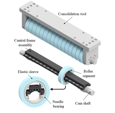
CONTIjoin segmented roller for consolidation tool. Photo Credit: BUSTI project, Fraunhofer IWS
The consolidation roller has been designed to apply consistent pressure throughout changes in laminate thickness and across the fuselage’s curved geometry. “The height of each roller segment adjusts via a camshaft in a central frame within the central core of the segmented roller,” explains Pohl. “Each roller segment also has a soft elastomer sleeve which increases the resulting contact area.”
Joint strength, future development
Results from slotted lap shear tests performed by Fraunhofer IWS to evaluate the strength of co-consolidated joints using the CONTIjoin process showed a reliable average strength of 30 megapascals is achievable. Nearly all samples exhibited some degree of substrate failure — indicating high joint strength — and failed mainly between the +45° and -45° layers of the butt strap laminates. In subsequent ILSS testing, the joint showed values 93% that of the press-consolidated reference.
“We have spent a lot of time in trials to assess the best process parameters,” says Pohl, “and simultaneously, we have built the welding setup.” The BUSTI team targeted July to complete installation of the welding setup at IFAM in Stade and August for commissioning the CONTIjoin equipment and process in preparation for the planned start of LH joint welding in September.
Even as MFFD progresses, Fraunhofer IWS is already advancing CONTIjoin further. At the end of 2022, it began another project with Airbus, this one funded by the German government, to develop the laser in-situ joining process for complex curved surfaces as compared to the single curvature of the MFFD fuselage. “We are now working on concepts for the consolidation tool,” says Pohl, “but we also have to develop the steering and software. With a single curvature, we can set up the path before the process. But now, we must develop a method to measure the exact complex curvature and software to calculate how the laser beam has to move at the given time intervals across the joint width.” This project will be completed in 2026.
CONTIjoin is just one technology that MFFD has enabled. “More than 40 technologies have been matured across Europe,” says Dr. York C. Roth at Airbus and leader of the Clean Aviation/Clean Sky 2 – Large Passenger Aircraft platform. “The MFFD is an outstanding example of what can be achieved if academia, research centers and industry OEMs and suppliers combine forces and align on a common objective. One partner alone would never have been able to deliver such a complex large-scale demonstrator.”
And this demonstrator is establishing a new knowledge base from which decisions for future aircraft will be made. “The technology bricks demonstrated in the MFFD project contribute to a much better understanding of thermoplastic composites as a material for fuselage primary structures,” says Ralf Herrmann, Airframe R&T at Airbus in Bremen and leader of the MFFD program. “A wide range of design solutions, manufacturing and assembly concepts have been developed through novel joining techniques and automation technologies. And these will enable the MFFD’s industrial partners to choose the the most appropriate technology for achieving the improvements in performance and reduced ecological footprint required for future aviation."


Related Content

Composites end markets: Sports and recreation (2025)
The use of composite materials in high-performance sporting goods continues to grow, with new advancements including thermoplastic and sustainability-focused materials and automated processes.
Read More
Braided thermoplastic composite H2 tanks with co-consolidated molded boss areas to fit EV battery space
BRYSON project demonstrates possible designs, automated manufacturing and low permeability concepts, including EVOH liner and novel PPA matrix.
Read More
Combining multifunctional thermoplastic composites, additive manufacturing for next-gen airframe structures
The DOMMINIO project combines AFP with 3D printed gyroid cores, embedded SHM sensors and smart materials for induction-driven disassembly of parts at end of life.
Read More
Assembling the Multifunctional Fuselage Demonstrator: The final welds
Building the all-thermoplastic composite fuselage demonstrator comes to an end with continuous ultrasonic welding of the RH longitudinal fuselage joint and resistance welding for coupling of the fuselage frames across the upper and lower halves.
Read MoreRead Next

Welding thermoplastic composites
Multiple methods advance toward faster robotic welds using new technology for increased volumes and larger aerostructures.
Read More
Thermoplastic composites: Poised to step forward
The evolving role of thermoplastic materials and processes and their future in next-generation commercial aircraft.
Read More
Ultrasonic welding for in-space manufacturing of CFRTP
Agile Ultrasonics and NASA trial robotic-compatible carbon fiber-reinforced thermoplastic ultrasonic welding technology for space structures.
Read More