
Welding thermoplastic composites
Multiple methods advance toward faster robotic welds using new technology for increased volumes and larger aerostructures.


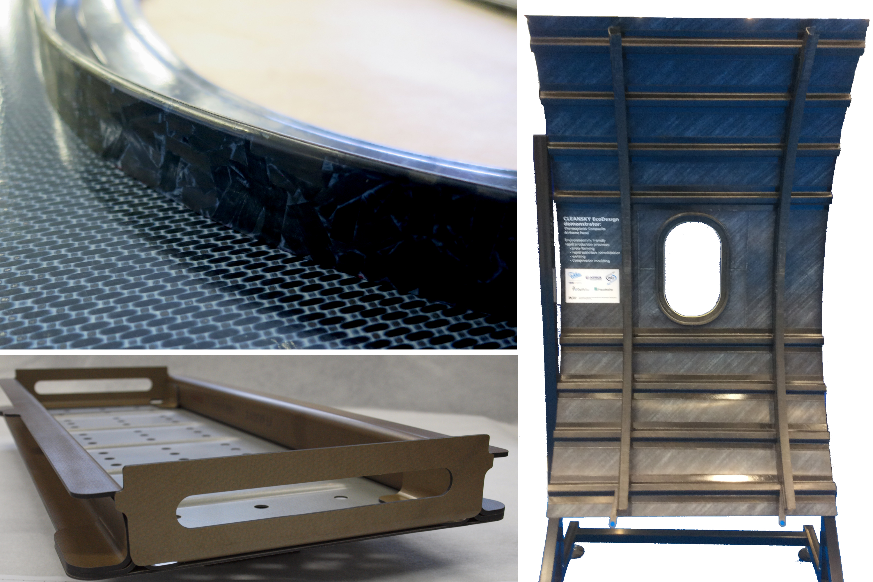
Welded thermoplastic composites: KVE Composites induction welded a CF/PEKK window frame (compression molded from UD tape cut into 1-inch lengths) to a CF fabric/PEKK skin (top left) for the Clean Sky 2 EcoDesign thermoplastic composite airframe panel demonstrator (right) on display at JEC 2018, as well as this aviation equipment rack (bottom left). Photo Credit: KVE Composites and CW, Ginger Gardiner
Unlike composites made with a thermoset matrix, thermoplastic composites (TPCs) require neither complex chemical reactions nor lengthy curing processes. Thermoplastic prepregs require no refrigeration, offering practically infinite shelf life. The polymers used in aerospace TPCs — polyphenylene sulfide (PPS), polyetherimide (PEI), polyetheretherketone (PEEK), polyetherketoneketone (PEKK) and polyarylketone (PAEK) — offer high damage tolerance in finished parts, as well as moisture and chemical resistance and, thus, do not degrade in hot/wet conditions. And they can be remelted, promising benefits in repair and end-of-life recyclability. But perhaps the greatest driver for TPC use in developing aircraft is the ability to join components via fusion bonding/welding. It presents an attractive alternative to the conventional methods — mechanical fastening and adhesive bonding — used to join thermoset composite (TSC) parts.
As defined in the widely cited paper, “Fusion Bonding/Welding of Thermoplastic Composites,” by Ali Yousefpour, National Research Council Canada (Ottawa, ON, Canada), “The process of fusion-bonding involves heating and melting the polymer on the bond surfaces of the components and then pressing these surfaces together for polymer solidification and consolidation.” The result is very different from thermoset joining.


“You are creating a unitized structure, such as a rib welded to a skin,” explains Arnt Offringa, head of Aerostructures R&T for GKN Fokker (Hoogeveen, The Netherlands). “When viewed under a microscope, you see just homogeneous polymer, so this is different than bonding. There is no dividing line, no split, no identifiable joining material such as adhesive. There is only one material, which is why you use the same polymer on both sides of the weld. Thus, authorities will accept such a join without mechanical fasteners.” (Offringa uses the word “join” here because the result of the welding process is not a joint, but one solid piece.)
In fact, such welded TPC structures have been flying for decades. And although resistance welding and induction welding are the two most established methods, others, including ultrasonic welding, laser welding and conduction welding, are being advanced for use with composites. Development of these methods continues as welding proponents seek the necessary reliability in predictive process simulation software, increased inline control of welding process variables, and extension of welding processes to production of aircraft primary structures.
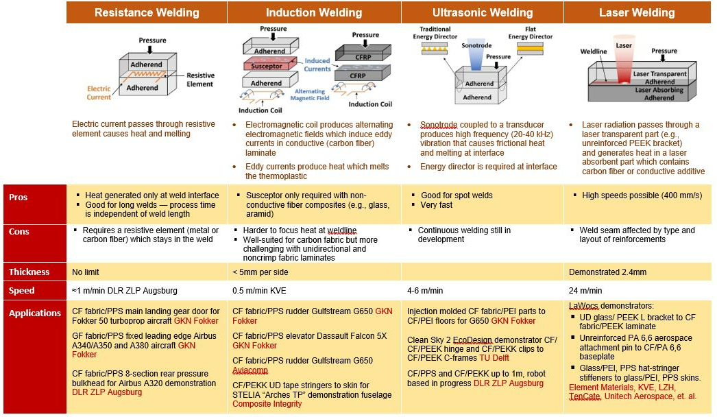
Advanced thermoplastic composite welding technologies. Photo Credit: CW
Resistance welding
Along with KVE Composites Group (The Hague, The Netherlands), GKN Fokker is an acknowledged leader in TPC welding development (see CW’s tour of Fokker Aerostructures). “We started with resistance welding in the early 1990s,” says Offringa. “The elegance of this method is that heat is produced exactly at the weld interface.” Electric current, passed through a resistive element at the weld interface, creates heat and melts the thermoplastic polymer (see table above). However, this resistive element — a metal or carbon fiber (CF) — stays in the finished part. “We developed a method using a PPS-coated metal mesh as the resistive element, and then certified and flew resistance-welded CF/PPS main landing gear doors on the Fokker 50 turboprop aircraft in 1998,” says Offringa. “This then led to conversations with Airbus UK (Broughton, Chester, UK) and the development of glass fiber/PPS fixed leading edges for the A340/A350 and then A380 widebody aircraft.” GKN Fokker has continued its resistance welding research, focused mainly on carbon fiber-reinforced plastic (CFRP).
CF resistance welded rear pressure bulkhead
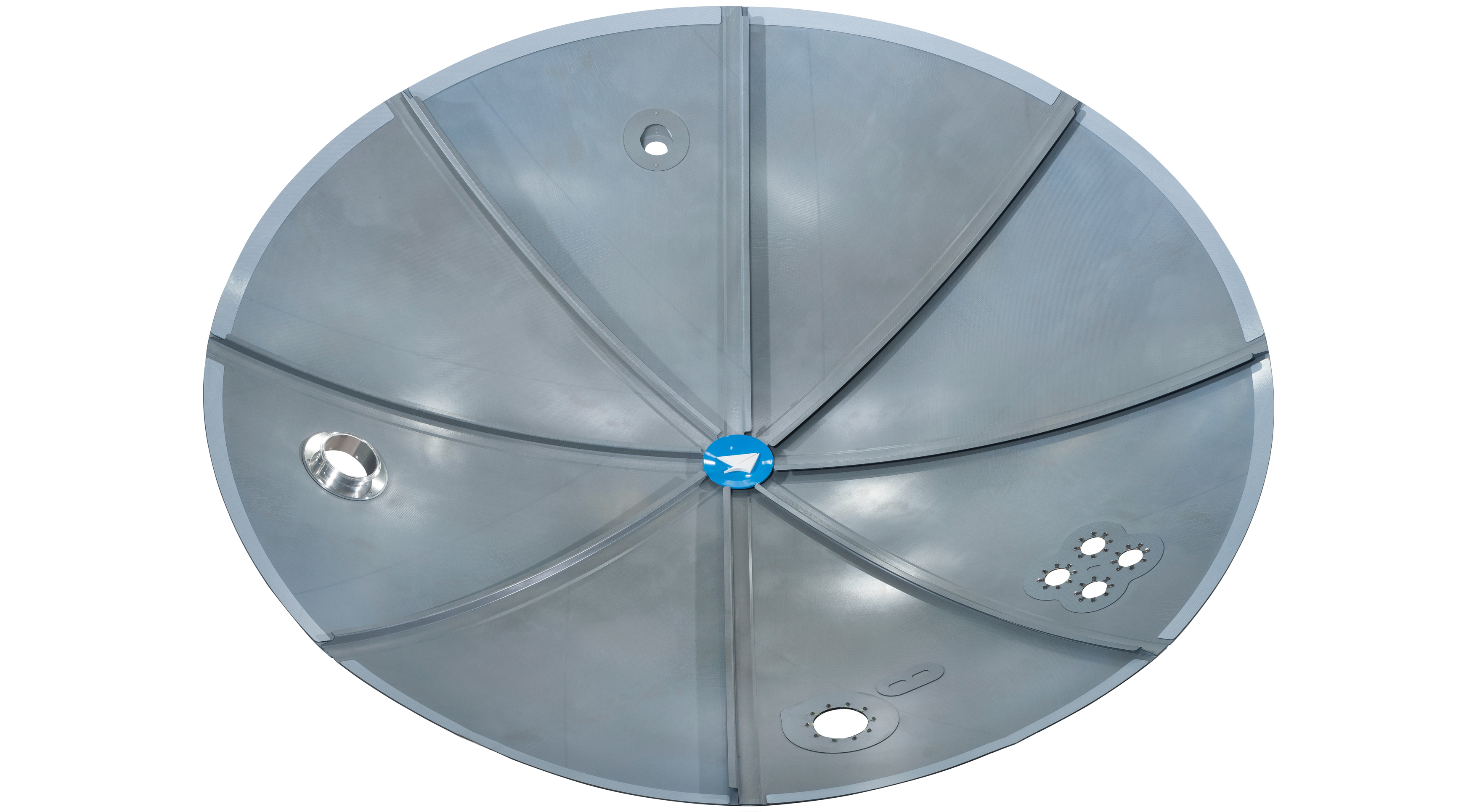
DLR’s Center for Lightweight Production Technology (ZLP) developed a resistance welding technique that uses carbon fiber instead of metal mesh for Premium Aerotec’s Airbus A320 rear pressure bulkhead demonstrator.
The technology has advanced. Premium AEROTEC (Augsburg, Germany) showcased an Airbus (Toulouse France) A320 rear pressure bulkhead demonstrator at the 2018 ILA Berlin Air Show. The bulkhead comprises eight press-formed CF fabric/PPS segments assembled via resistance welding. “We have been using resistance welding for some time,” says Dr. Michael Kupke, head of the Center for Lightweight Production Technology (ZLP) for the German Aerospace Center (DLR) in Augsburg. “For the Premium AEROTEC demonstrator, we extended the weldline length to 1.5m.”
ZLP chose a resistive element made from carbon fiber vs. legacy stainless steel mesh. “For induction welding, it’s difficult to get the temperature and energy where you want it and not elsewhere in the part,” Kupke asserts. “For resistance welding, this is inherently solved, but the downside, up to now, has been that the resistor remains in the part.” Using a carbon fiber resistor alleviates this disadvantage.
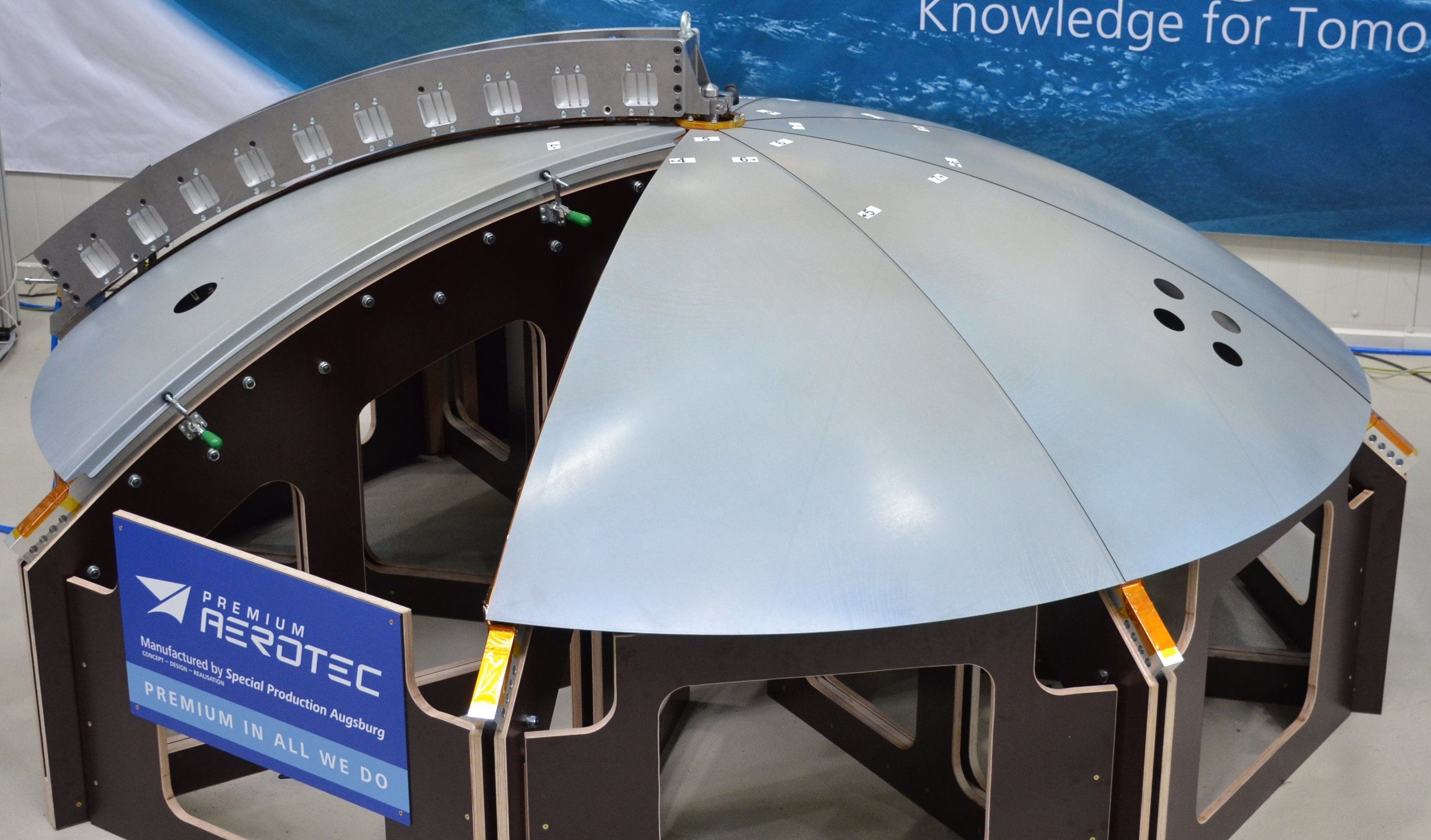
A curved metal “welding bridge” rotates to position each of the eight weldlines in the A320 rear pressure bulkhead demonstrator. Photo Credit: Premium Aerotec and DLR
The basic method, however, remains the same. “You apply a voltage and put pressure on both parts to get good consolidation,” he adds. “For smaller parts, the robotic end effector applies the pressure, but for larger parts you would need a jig to provide clamping pressure.” The jig for the A320 rear pressure bulkhead is a curved metal “welding bridge” built by Premium AEROTEC. It rotates to position above each of the eight weldlines and applies the necessary pressure via 10 pneumatic cylinders inside.
In addition to PPS, Kupke’s DLR ZLP team has validated that this process also works for carbon fiber fabric/PEEK. “If you can use PEEK, you can adapt to PEKK, PAEK and PEI,” he adds. “We should be able to weld unidirectional (UD) tape as well,” he also notes (challenges associated with welding UD tapes are explained below). Kupke says there is no limit to the part thickness being welded, “it could be 3 mm or 30 mm, but care must be taken with thermal management at the weldline.”
He says the next step will be to develop a range of optimized CF resistive elements. “We’ve just used off-the-shelf materials for now.” Kupke points outs this was only a demonstrator, not an industrial process. “To industrialize, we would do it a bit differently. The welding process for each join in the A320 bulkhead took 4 minutes, however, only 90 seconds of welding current was applied. The remaining time was for heating and cooling of the PPS thermoplastic at the weldline. With industrialization, we believe the total time would be faster and the welding would still take only 60-90 seconds per 1.5m join.”
Induction welding
KVE began working with induction welding in the early 2000s. The basic technique involves moving an induction coil along the weldline. The coil induces eddy currents in the inherently conductive CFRP laminate, which generate heat and melt the thermoplastic. “We began with single-lap shear coupons, following the building block approach, and progressed to L-joints, T-joints, then basic structures and finally elevators and rudders,” recalls KVE managing director Harm van Engelen.
The company developed computer simulations in parallel. “Simulation helps you to predict what the temperature will be at the outer surface and at the weldline,” he explains. “You need to concentrate heat in the weldline, but not overheat adjoining sections. The top surface heats up faster than the interface, so you have to get rid of that heat.” KVE patented not only the resulting heat management technology and tooling materials, but also its tooling-based approach to maintaining pressure during welding, and its robotic control of the induction coil and weldhead, which it developed by 2005.
“This provided an alternative to resistance welding for CFRP that did not require a susceptor or welding strip,” says GKN Fokker’s Offringa. “We licensed the KVE technology and implemented it on the Gulfstream G650 elevators and rudder, which have been flying since 2008.” KVE was a key partner in the development and industrialization of the robotic induction welding process. A refined second-generation technique is used for the elevators and rudder on the Dassault Falcon 5X. Van Engelen notes that welding for the G650 was automated but completed in multiple steps. “For the Dassault, it is done in one shot,” he adds. “All of the parts are placed in the tools and then two elevators and a rudder are welded in one shift overnight.”
By 2008, KVE had begun single-lap shear (SLS) testing of UD CF/PEKK tape and was producing demonstrators for the Thermoplastic Affordable Primary Aircraft Structure (TAPAS) program. By 2010, it had completed 3D simulations of induction-welded UD CF laminates with lightning strike protection (LSP) and had worked with thick laminates (≤5 mm for UD PEEK and PEKK, ≤15 mm for carbon fiber fabric/PPS). KVE had also designed and built a TPC rudder for The Boeing Co.’s (Chicago, IL, US) Phantom Eye UAV, which Boeing then began producing in 2011. By 2014, the company had produced induction-welded UD CF/PEKK demonstrators and is now working with multiple OEMs and Tier 1 suppliers to help qualify this technology for other aircraft structures.
Moving from fabric to UD tape
Induction welding is well suited for carbon fiber fabric, says Offringa, “but with UD tape, there is a new set of challenges to reach production speeds.” As explained by Dr. Michel van Tooren, director of the SmartState Center for Multifunctional Materials and Structures, part of the McNair Center at the University of South Carolina (Columbia, SC, US), “For induction in CFRP laminates, you need fibers at two different angles — preferably angles as far away as possible — for eddy currents to be generated.” The perpendicular 0° and 90° fiber orientation in woven fabric is ideal, enabling eddy currents to be generated in each ply of the laminate. With UD laminate stacks, however, it is common to have 45° plies interspersed so that the angle difference is smaller. “The eddy current heating mechanism is affected because these directions are not perpendicular, adds Maarten Labordus, head of R&D at KVE. “There also is no distinct fiber crossover between the plies, they are just layered. Thus, you need more power to induce current compared to fabric laminates.”
However, adding more power does not make managing the welding process easier. Balancing electrical power and temperature at the weldline is not straight-forward because the induction welding process not only changes with stacking sequence but also with laminate thickness and part geometry. “So we look at the process parameters and how heat is generated in the materials,” says Sebastiaan Wijskamp, TPRC’s technical director. “We want to have guidelines and design tools to predict weld performance ahead of time. If you want to switch from fabric to UD, how can you do this quickly without having to go through a trial-and-error process? Ideally, simulations based on the electrical and thermal conductivity properties of fibers and polymers, even for a certain layup, and also factoring in part geometry, would allow you to design your welding process per part. We are performing collaborative research with KVE and Michel van Tooren at the McNair Center to develop the fundamental understanding for these guidelines and tools.”
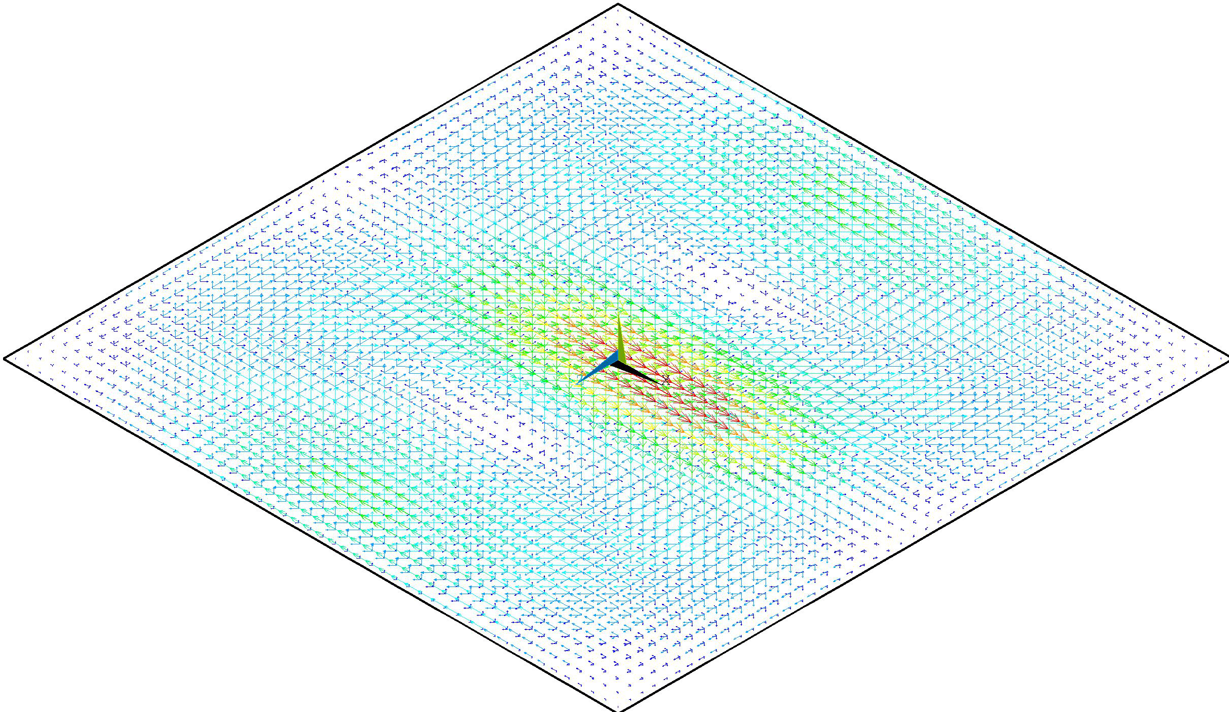
Induction welding matures for industrialization
Computer simulation is advancing beyond fabric laminates to UD materials — for example, this analysis shows the direction of eddy currents being generated — offering the ability to predict performance when switching to new materials and define optimal coil shape, power, robot speed and heating profile for a given application. SOURCE: KVE Composites
“We’re quantifying all of these factors — UD vs. fabric, stacking sequence, areas of more resin and less resin — and establishing their relationship, then we add this back into the general welding model,” explains Labordus. Areas with high resin content act as an isolator, retarding heat, while areas where resin content is lower (and fiber content is higher) facilitate heating. “At first, we were 40% off our welding predictions with UD, but now we are within 10% and are getting close to our high-accuracy levels for CF fabric/PPS,” Labordus adds.
Van Tooren also is close to being able to predict induction welding performance for UD laminates. “By the end of 2018, we will have a simulation tool that works for relatively simple geometries, helping to identify the necessary coil shape, power, robot speed and heating profile for a given application.” This prediction capability is being developed in parallel with physical testing to support the use of welded TPC components in larger primary structures for future aircraft.
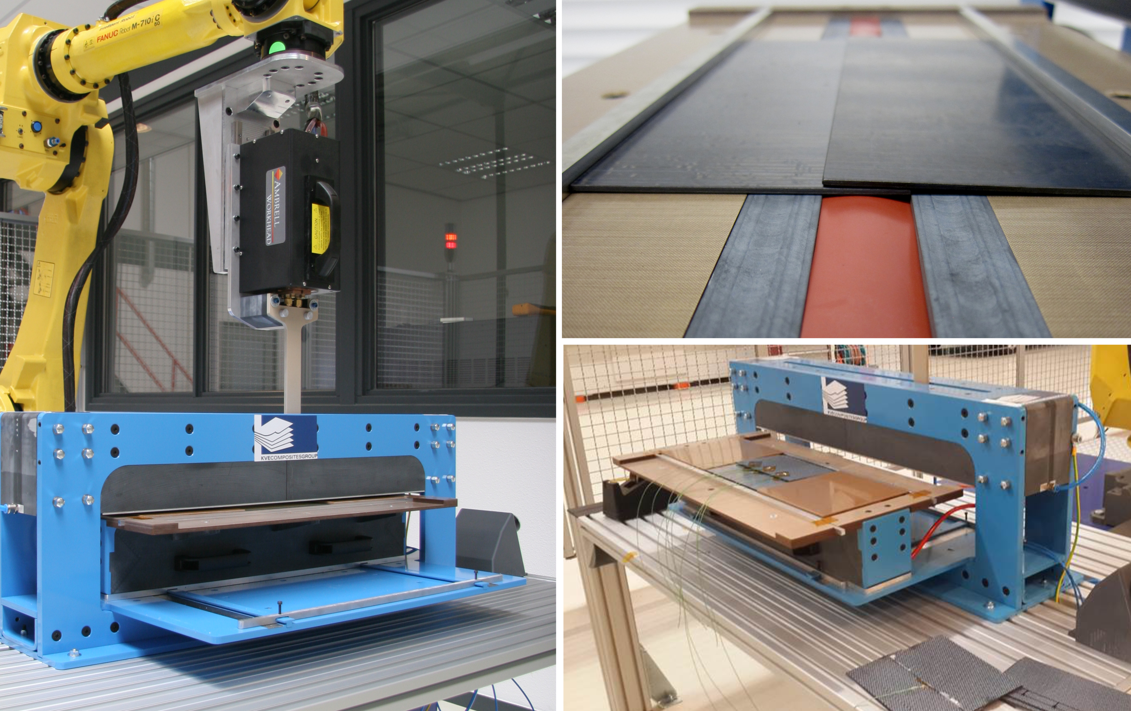
Qualification for future airframes
KVE Composites has developed a standardized induction welding setup to support process qualification at OEMs and Tier 1 suppliers (left), which produces single-lap shear coupons (above) as well as L– and T-stringers. Photo Credit: TPRC and KVE Composites
Van Tooren’s lab is a research partner with KVE and one of four sites — along with KVE’s facility in The Hague, the Netherlands Aerospace Centre (NLR, Amsterdam) and ThermoPlastic composites Research Center (TPRC, Enschede, The Netherlands) — that has installed a standardized induction welding setup developed by KVE to support process qualification at OEMs and Tier 1 suppliers (see “New horizons in welding thermoplastic composites”).
Bespoke induction coils
An alternative induction welding approach has been used by Composite Integrity (Porcelette, France) to develop the “dynamic induction welding” process used to join CF/PEKK UD tape stringers and fuselage skins in the STELIA Aerospace (Toulouse, France) Arches TP structure demonstration project, unveiled at the 2017 Paris Air Show (see image below). Composite Integrity is the composites division within the Institut de Soudure (IS Groupe, Villepinte, France). “We draw off more than 100 years of IS Groupe experience in welding metals to design and build our own induction coils optimized for each material, thickness and part shape, including specific coils for woven fabric, noncrimp fabric and UD,” explains Composite Integrity business development manager Jérôme Raynal. “The major problem with UD is that there are no welding nodes to generate induction current, so we need a specific coil — in this case, a multi-coil.”
Founded as Pôle de Plasturgie de l’Est (PPE) 25 years ago, Composite Integrity is a leader in resin transfer molding (RTM) and epoxy resin-infused aircraft structures with French aerospace companies. Incorporated into the IS Groupe in 2016, it has worked with Aviacomp (Launaguet, France) to develop co-consolidation welding technology used in TPC fuel access doors for the Airbus A350 aircraft. “Resistive components on the surface of the molded inner and outer composite parts put heat into the weldline,” says Raynal.
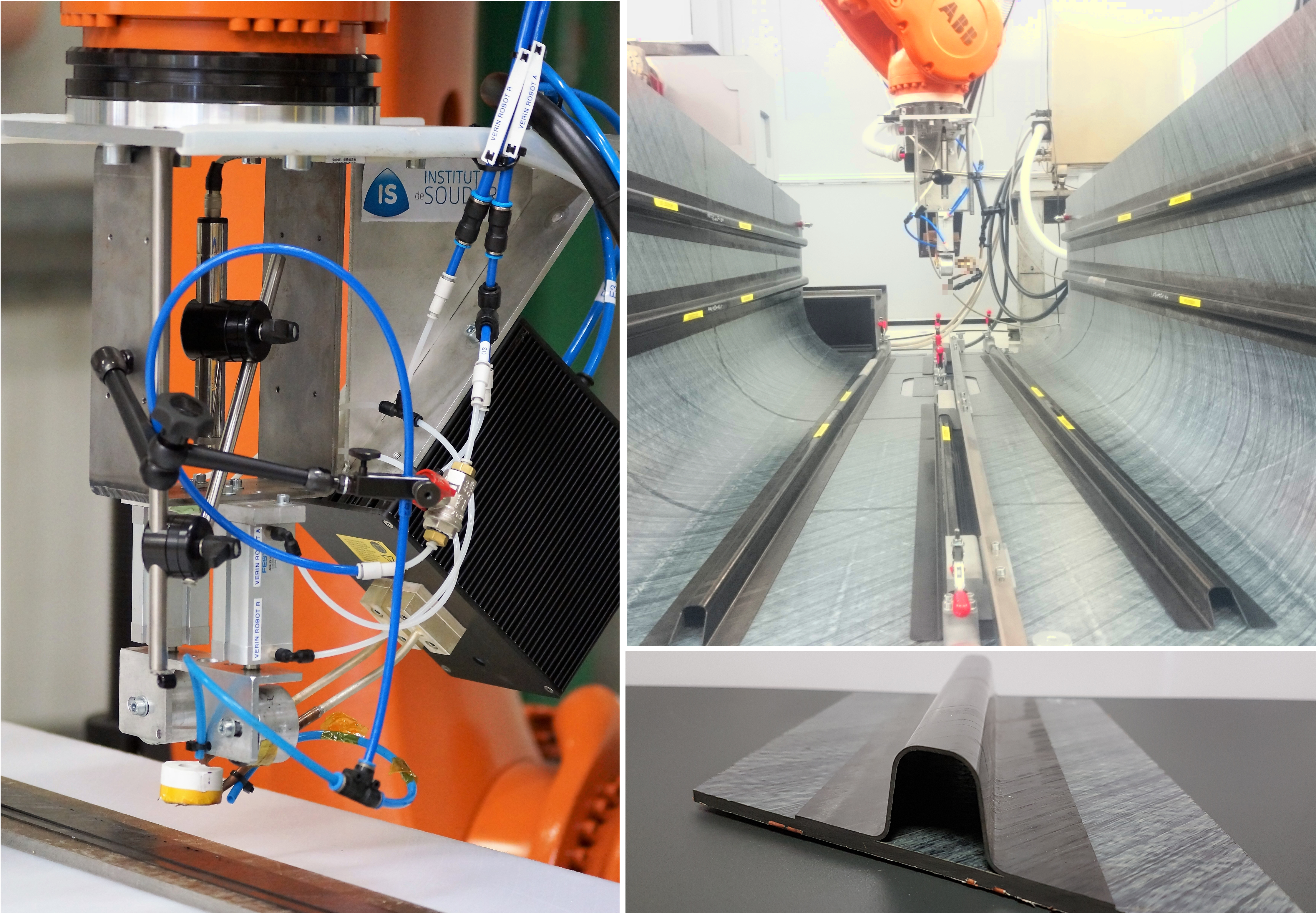
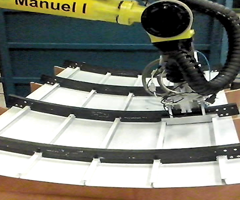
Dynamic induction welded STELIA demonstrator
Composite Integrity developed a customized coil and process to weld UD CF/PEKK stringers and skin while accommodating for thickness changes in both for the Arches TP structure demonstrator. Photo Credit: Composite Integrity
Composite Integrity began working on the STELIA Arches TP project in 2015, enabling induction welding of fuselage-sized, curved parts. The process is described as “dynamic” because the robot welds the stringers down the length of the fuselage and accommodates 3D shapes, including movement in the z-direction during welding. “Both the stringers and skin in the STELIA demonstrator have a change in thickness,” Raynal explains. An aluminum rail serves as fixation jig to prevent movement of the stringer on the skin as it is welded. For the demonstrator, pressure was applied via two rollers in the welding head. These sit above the coil. During welding, the rollers run along the stringer, next to the fixation rail while the coil is traveling over the weldline.
“We have now developed a new, patent-pending welding head, which uses a single roller and increases the weldline mechanical properties,” Raynal notes. “We also have a cooling device blowing air on the welding surface in pressure to be sure we are below the crystallization temperature, so there is no risk of de-compaction once pressure is released.”
Provision for cooling also affects the crystallinity of the thermoplastic matrix at the weldline. “We test to measure that crystallinity meets the aerospace standards and then establish the corresponding parameters for the welding process,” Raynal explains. Speed is also a factor. “For the demonstrator, the speed was 2 m/min, but our target now is 5 m/min,” he says. “Managing the cooldown and crystallinity of PEEK and PEKK are more complicated, which affects the global speed of welding, but we have good results with both, using conventional organosheet qualified by Airbus.” The maximum thickness of parts welded thus far is 5 mm. “We have demonstrated this, which is roughly the thickness you would have in structural components,” Raynal observes. “For STELIA, we used the carbon fiber as the conductor with no metal in the interface, but now we are developing technology to weld any fiber — glass fiber, for example — without a metal mesh as well. We don’t add material at the interface yet can weld UD to woven and UD to UD, without problem,” he claims.
Ultrasonic welding
The third most common technique, ultrasonic welding is another technology with which GKN Fokker has logged significant experience. The process uses a sonotrode to generate high-frequency (20-40 kHz) vibrations that cause frictional heat and melting at the weld surfaces.
“This is good for spot welds,” says Offringa, noting that for Gulfstream aircraft, “We have used ultrasonic welding for joining more than 50,000 injection molded TPC parts to floor panels. It is very fast and highly automated, but it’s a spot weld, at only one location.” Still, he sees potential for this method in production of an integrated fuselage, like that proposed in the Clean Sky 2 program’s Multifunctional Fuselage Demonstrator (see “New horizons in welding thermoplastic composites”). “Fuselage brackets are often bonded, riveted or bolted to current thermoset composite fuselage structures,” Offringa observes. “With ultrasonic welding, you can achieve very good connection with brackets, which are often unreinforced thermoplastic.”
Ultrasonic welding has been used with plastics for several decades, typically with energy directors at the weld interface. These triangular or rectangular ridges of neat resin, molded into the surfaces to be welded, increase local heat generation. However, Irene Fernandez Villegas at Delft University of Technology (TU Delft, Delft, The Netherlands) has shown that 0.08-mm thick, unreinforced thermoplastic films may be used in their place. “She is working to develop continuous ultrasonic welding,” says Offringa, and this work is continuing within Clean Sky 2.
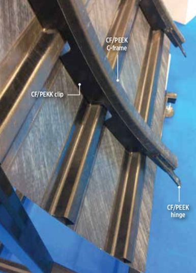
Sequential ultrasonic spot welding
Lab-scale sequential ultrasonic spot welding was used to attach CF/PEEK hinges and CF/PEKK clips to CF/PEEK C-frames in the Clean Sky EcoDesign demonstrator. Photo Credit: CW, Ginger Gardiner
In her 2016 paper, titled “Smart ultrasonic welding of thermoplastic composites,” Villegas states that it is possible to scale up the ultrasonic welding process via sequential welding — that is, letting a continuous line of adjacent spot welds serve the same purpose as a continuous weld bead. Lab-scale sequential spot welding was used in the Clean Sky EcoDesign demonstrator’s TPC airframe panel, using flat energy directors to weld a CF/PEEK hinge and CF/PEKK clips to CF/PEEK C-frames. Experimental comparisons with mechanically fastened joints in double-lap shear and pull-through tests showed promise. The process is further explored in 2018 papers by Villegas’ TU Delft team member Tian Zhao.
Kupke reports that DLR ZLP also is working on robot-based continuous ultrasonic welding. “Spot welding is the current state of the art, but ours is truly continuous,” he says. “We are optimizing the process on a roughly 1m-long test bench, performing parametric studies using different materials and configurations. Though the welding machine and digital control are designed for a robot manipulator, we are still exploring how to refine the head and which velocity and energy works best for each material and laminate thickness. Our objective is to show you could do very long welding, such as the joints of a fuselage.”
Laser welding
Although laser transmission welding was discussed in Yousefpour’s 2004 review of TPC welding technologies, it has since been advanced significantly by Laser Zentrum Hannover e.V. (LZH, Hannover, Germany). In this process, laser light is first passed through a part that is transparent or partially transparent in the near infrared spectral range (e.g., an unreinforced thermoplastic or glass fiber TPC). The light is then absorbed by carbon fiber or conductive additives in a second adjacent part, transforming the laser energy into heat, which creates the weld between the two materials.
Offringa at GKN Fokker points out that many injection molded aircraft brackets are laser transparent. He sees great potential for using laser welding to achieve assembly of these brackets to CFRP fuselage structures without holes, dust or fasteners. Though both reinforcement type and laminate thickness affect the weld, LZH has demonstrated good results with glass fiber and carbon fiber-reinforced PPS and polyetherimide (PEI) laminates in the Laser Transmission Welding of Thermoplastic Composite Structures project (LaWoCS, 2010-2013), which also included KVE, TenCate Advanced Composites (Nijverdal, The Netherlands), Unitech Aerospace (Yeovil, UK) and Element Materials Technology (Hitchin, UK). LZH has patented this technology and was a 2018 JEC World Innovation Award finalist in the aerospace applications category for “Modular Thermoplastic Stiffening Panels” where a stamp-formed CFRTP stiffening grid is laser-welded to a composite skin. Project partners included German firms Fraunhofer ICT (Pfinztal), Airbus Operations (Hamburg), ElringKlinger (Dettingen an der Erms) and KMS Automation (Schramberg), as well as TenCate.
Conduction welding
Process time independent of weld length
Conduction welding is a new technology being used by GKN Fokker (Hoogeveen, The Netherlands) that uses a kind of hot iron to supply heat along the weldline in seconds. Like resistance welding, process time is independent of weld length, making it attractive for joining 6-10m-long TPC stringers to fuselage skins. Photo Credit: GKN Fokker
After industrializing induction welding, GKN Fokker developed conduction welding. “This is a new technology,” says Offringa. “A kind of hot iron is used to conduct heat through at least one of the parts to be joined. Like resistance welding, the process time is independent of weld length — so whether the join is a half meter or 10m, the process time is the same for both.” This is because both techniques use electricity to supply heat along the length within seconds. The TPC orthogrid fuselage panel displayed at JEC 2014 featured conduction welding. “The frames were welded in a second step using a robot with a welding end-effector,” says Offringa. “The fuselage panel was curved and the frames were fairly short. However, this method could work well for welding 6-10m-long stringers to fuselage skins.”
Inline process control and beyond
A key step in maturing TPC welding for fuselage structures is the ability to monitor and manage the process in situ. “Right now, our induction welding process is preconfigured,” says van Engelen at KVE. “We use thermocouples in the weldline to calibrate the process. But we prefer to measure the temperature in the weld and feed that back to manage the power to the coil.”
“Our welding processes are digitally controlled and all process data is stored,” says Offringa at GKN Fokker, “but we are moving toward inline process control, based on real-time temperature measurement.” He believes this is possible for induction and resistance welding within a few years, while ultrasonic welding is already fairly close. Villegas at TU Delft states that in-situ process monitoring of sequential ultrasonic welding is possible based on the power and displacement curves provided by the welding machine, which make it possible to quickly define optimum processing parameters.
In addition to process control, KVE is also working on inline inspection. “If the weld shows a problem, we just go back and reweld it,” says van Engelen.
“This is why thermoplastic composites are so good,” notes Raynal at Composite Integrity. “Rewelding does not hurt them. We have specific technology to weld and de-weld with resistance welding to disassemble by injecting current.” His company is also developing inline inspection. “We will have a thermographic cell just after the induction welding head and check the weld using live thermography,” says Raynal. Van Tooren is also pursuing in-situ process monitoring and inspection, but using fiber-optic sensors, including the ODiSI system from Luna (Roanoke, VA, US), which provides more than 1,000 sensor points per meter.
TPRC and van Tooren each have ongoing projects to develop inline process control for induction welding of large, curved structures and varying thicknesses, including ply buildups and drop-offs in stringers. Van Tooren is also developing induction welding under a vacuum bag. “It becomes like soft tooling for compression of the two surfaces being welded,” he says, and is currently aimed at potential repair applications (see “New horizons in welding thermoplastic composites”). Van Engelen’s list of KVE future developments also includes TPC repair, induction welding of glass fiber TPCs, nonaerospace applications and flux concentrators. “We are developing reflective materials to concentrate the electromagnetic field at the weldline,” he explains. “You want to put the energy here instead of at the part’s outer surface. With these flux concentrators, you direct the energy, similar to how you direct fiber where you want, using automated placement.”
“We are still developing all of the welding technologies,” Offringa sums up, “and exploring new ones. Most importantly, we don’t think there is a single technology with the most promise, but that each has its place.”
Wijskamp notes that with the recent Clean Sky 2 calls for proposals, it has become clear that Airbus wants to use welded TPCs in large airframe structures. “But we have seen this already in our 19 partners that have joined since 2009,” he adds.
Van Tooren believes that a welded, fastenerless, large component, if not a full fuselage, is within reach. “Preferably, on the Boeing New Midsize Airplane, but definitely the next aircraft.”


.jpg;maxWidth=300;quality=90;format=webp)
Related Content

Plant tour: Joby Aviation, Marina, Calif., U.S.
As the advanced air mobility market begins to take shape, market leader Joby Aviation works to industrialize composites manufacturing for its first-generation, composites-intensive, all-electric air taxi.
Read More
The potential for thermoplastic composite nacelles
Collins Aerospace draws on global team, decades of experience to demonstrate large, curved AFP and welded structures for the next generation of aircraft.
Read More
Manufacturing the MFFD thermoplastic composite fuselage
Demonstrator’s upper, lower shells and assembly prove materials and new processes for lighter, cheaper and more sustainable high-rate future aircraft.
Read More
Cycling forward with bike frame materials and processes
Fine-tuning of conventional materials and processes characterizes today’s CFRP bicycle frame manufacturing, whether in the large factories of Asia or at reshored facilities in North America and Europe. Thermoplastic resins and automated processes are on the horizon, though likely years away from high-volume production levels.
Read MoreRead Next

Composites end markets: Energy (2024)
Composites are used widely in oil/gas, wind and other renewable energy applications. Despite market challenges, growth potential and innovation for composites continue.
Read More
CW’s 2024 Top Shops survey offers new approach to benchmarking
Respondents that complete the survey by April 30, 2024, have the chance to be recognized as an honoree.
Read More
From the CW Archives: The tale of the thermoplastic cryotank
In 2006, guest columnist Bob Hartunian related the story of his efforts two decades prior, while at McDonnell Douglas, to develop a thermoplastic composite crytank for hydrogen storage. He learned a lot of lessons.
Read More