


Within MFFD, there are dozens of individual projects and work packages. Two at the forefront are STUNNING (SmarT mUlti-fuNctionNal and INtegrated thermoplastic fuselaGe), which will develop and manufacture the lower half of the MFFD, and MECATESTERS (Micro mEchanical Characterization of A ThErmoplastic Co-conSolidated/welded joinT for usE in aiRcraft fuSelages), which is part of STUNNING.


“MECATESTERS will study in-depth induction welding using the latest grades of Toray Advanced Composites (Morgan Hill, Calif., U.S.) LM PAEK UD tape materials and compare those to the Solvay Cytec (Alpharetta, Ga., U.S.) UD PEKK material already thoroughly explored and demonstrated in the TAPAS 1 and TAPAS 2 programs, next to the original version of the Toray LM PAEK UD tape material,” explains Maarten Labordus, head of R&D for induction welding pioneer KVE Composites Group (The Hague, Netherlands). Toray Advanced Composites, previously TenCate Advanced Composites (Nijverdal, Netherlands), played a leading role in both TAPAS projects.
I’m going to start with Clean Sky 2 and MFFD, and then walk through STUNNING and MECATESTERS before returning to MFFD assembly, automation and timeline.
Clean Sky 2 and MFFD
Clean Sky 2 is a European partnership for technology development to reduce aircraft noise, emissions and carbon footprint via more aerodynamic wings, lighter and more efficient engines, new aircraft configurations and smarter systems. Composites feature heavily in many Clean Sky projects, but metals are also being developed.
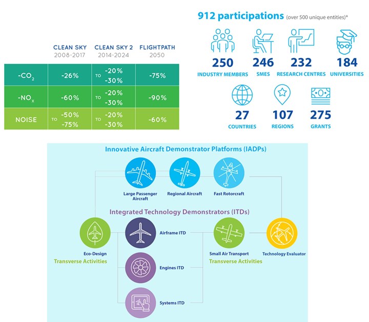
Edited infographic showing Clean Sky goals, participation and organization of large demonstrators. SOURCE | Clean Sky 2.
This type of aeronautical research began with the European Commission Framework Programme (FP) for R&D funding, spanning FP2 (1987-1991) to FP7 (2007-2013). These programs have contributed substantially to maturing a wide variety of technologies to technology readiness level (TRL) 6 and implementation in aircraft such as the Airbus A350.
One of the differences in Clean Sky 2 is its organization around large demonstrators. The MFFD is one of three full-scale fuselage sections being produced within the Large Passenger Aircraft (LPA) Innovative Aircraft Demonstrator Platform (IADP) (see blue text at top of blue square in infographic above). Within the LPA IAPD there are three platforms. The MFFD sits within Platform 2 “Innovative Physical Integration Cabin-System-Structure,” which features two other large demonstrators.

The MFFD is one of three large demonstrators in Platform 2 within the Clean Sky 2 Large Passenger Aircraft IADP. SOURCE | Clean Sky 2 Information Day CfP 09, presentation by Jens Koenig, Airbus, Nov. 2018 and Clean Sky 2 “Large Passenger Aircraft”, edited by CW.
To understand what this means, I go back to something Airbus Airframe Research & Technology (R&T) engineers from Getafe, Spain, told me as I was researching multifunctional composites in 2015. They said, in essence, “We no longer want the duplication and waste of making an exterior structural cylinder and an interiors cylinder; we want to integrate the structural airframe with the cabin systems.” I struggled to visualize what this meant — until I saw a sketch of the MFFD.
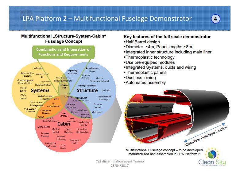
SOURCE | Clean Sky 2 (CS2) dissemination and “Thermoplastic composite demonstrators — EU roadmap for future airframes”.
“Modularity, integration and creating common platforms are key,” says Ralf Herrmann, Airframe R&T Typical Fuselage at Airbus Operations GmbH (Bremen, Germany) and leader of the MFFD program. I am quoting here from the MFFD page on the Clean Sky 2 website:
Herrmann: "We've known for a long time that the benefits of weight reduction and the lowering of recurring costs in aircraft production — when using thermoplastic composites — can only be achieved by the integration of several disciplines. This means that focusing on the structure alone cannot achieve the full benefit of composites technology.”
The versatility of thermoplastics needs to be applied in combination with a design approach, according to Clean Sky 2 project officer Paolo Trinchieri: “It is necessary to remove the artificial separation of functions at the aircraft pre-design stage and to plan for a high production rate of aircraft manufacturing, assembly and installation right at the start.”
Herrmann was previously the project manager for the FP7 project MAAXIMUS (More Affordable Aircraft structure through eXtended, Integrated, & Mature nUmerical Sizing). Running from April 2008 to September 2016, MAAXIMUS included 60 partners and aimed to demonstrate the fast development and right-first-time validation — by maturing virtual and physical enablers simultaneously — of a highly optimized composite fuselage to achieve 50% reduction in assembly time of large fuselage sections, 10% cut in recurring costs, 10% lower structural weight and a 20% shorter development cycle. The MFFD’s goals can be seen as an extension:
- Enable production rates of 70-100 aircraft/month
- Reduce fuselage weight by 1,000 kg
- Reduce recurring costs by 20%.
One key enabler is dustless joining (no holes, no fasteners) via welded thermoplastic composite components. Herrmann explains that the current sequential approach to aircraft manufacture — where the fuselage structure must be fairly complete before systems plus cabin and cargo features can be installed — is time-consuming and “failure-sensitive”. Instead, MFFD pursues pre-equipped, highly integrated structural elements and system modules that can be installed quite early, long before final assembly.
Change to longitudinal joints and LM PAEK
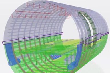
Figure 1: Illustration of the intermediate overall MFFD design with the longitudinal joints highlighted (purple). SOURCE | Annex: Clean Sky 11th Call for Proposals – List and Full Description of Topics, 21 November 2019, p. 77
MFFD project activities started in 2017. Every year there is at least one call for proposals (CFP) in which project leaders outline topics that need further development. As can be seen in the image below, the bias joint design shown in CFP08 (April 2018) had changed to a longitudinal joint by CFP09 (Sep 2018).
“The bias joint presented issues regarding accessibility and attachment of floor structures that we realized would be hard to overcome within the given timeframe,” Herrmann explains. “So, we decided to fall back to the conventional design in order to lower the risk. Our main interest is to show how to integrate all of the systems and cabin elements that can be installed before Main Components Assembly (MCA). This will also be the first time that this thermoplastic composite material is applied in full-scale, primary fuselage structures for large passenger aircraft.”
The MFFD design changed from a bias joint design to a more conventional longitudinal joint in 2018. SOURCE | CFP08 p.87 (left) and CFP09 p. 133 (right).
Another change was in the thermoplastic composite (TPC) matrix material. MFFD topics in CFP08 and CFP09 refer to carbon fiber/PEKK (polyetherketoneketone), but by CFP10 (March 2019), the baseline material was described as carbon fiber and PAEK (polyaryletherketone). PAEK is the overall family of polymers within which PEEK, PEKK and LM PAEK reside.
As described in my blog on PEEK vs. PEKK vs. PAEK, Cetex material supplier TenCate, now Toray Advanced Composites, produces all three polymers as carbon fiber-reinforced tape and claims the properties are basically the same. However, Cetex TC1225 CF/LM PAEK tape melts at 305°C while TC1320 CF/PEKK tape melts at 340°C. And, according to Toray Advanced Composites global CTO Scott Unger, “LM PAEK has much better flow … and also can be processed at higher speeds than PEKK and PEEK.” TC1225 also costs less.
MFFD lower fuselage: project STUNNING
STUNNING is the project name for the development and manufacture of the fully equipped lower half of the MFFD. The project aims to further mature:
- Automated assembly processes
- Thermoplastic manufacturing and assembly technologies
- Integrated design and manufacturing development technologies
- Development of advanced electrical systems architectures.
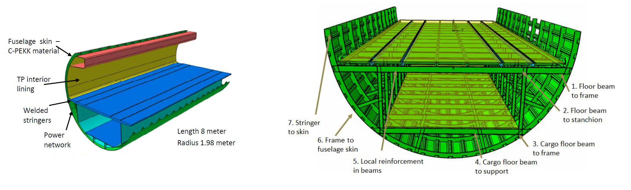
Bas Veldman, program manager at GKN Fokker (Hoogeveen, Netherlands) and project manager for STUNNING, explains that the MFFD will be 8 meters long and 4 meters wide with a radius of 2 to 2.5 meters, which is real scale for a single-aisle A320 family aircraft. “It is similar to the A321, which is not exactly circular but roughly egg-shaped (a bit higher than wide),” he adds.
The 180° lower fuselage section will comprise the lower fuselage shell with welded stringers and frames, the cabin and cargo floor structure, and relevant main interior and system elements. “We will deliver large, pre-outfitted modules for very rapid, plug-and-play assembly,” says Veldman.
GKN Fokker is the lead partner in STUNNING and has four divisions participating, including Aerostructures (Papendrecht, Netherlands), Fokker ELMO (Hoogerheide, Netherlands), GKN Fokker Engineering Romania (Bucharest) and GKN Fokker Technologies (Papendredcht, Netherlands). GKN Fokker ELMO is a supplier of aircraft wiring harnesses and electrical systems technology. “It is responsible for the systems architecture in STUNNING and will focus on optimizing the electrical system,” Veldman explains, “and collaborates with the CFP08 consortium MISSION on the development of an innovative power bus system.”
“Diehl Aviation (Laupheim, Germany) is responsible for the interior structure, including subsystems and the floor, sidewall panels and how they are joined, monument interfaces and smart system multiports,” Veldman continues. “NLR (Netherlands Aerospace Centre, Amsterdam) is responsible for manufacturing the fuselage skin and stringers, and TU Delft is assisting with assembly, based on its expertise with ultrasonic welding.” (See “Welding thermoplastic composites” for more on ultrasonic welding.)
MECATESTERS welding test program
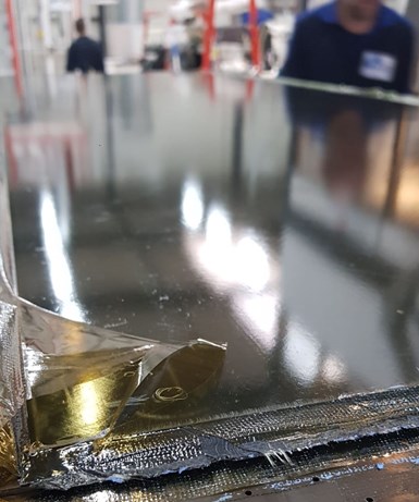
Autoclave-cured test panel made using Toray Advanced Composites TC1225 UD carbon fiber/LM PAEK tape for the MECATESTERS program. SOURCE | KVE Composites.
“STUNNING has launched seven CFP topics and five have begun work, including MAYA, MISSION, EMOTION, TCTool and MECATESTERS,” says Veldman. The latter is a large welding test program with KVE Composites (The Hague, Netherlands) and Rescoll (Pessac, France) that started in April 2019 with a duration of 30 months. Veldman explains that although KVE has a long history with induction welding of both fabric and UD tape thermoplastic composites, the induction welded parts flying on aircraft to date have used fabric. “In STUNNING we are establishing best practices with UD reinforcements and LM PAEK materials, and also comparing induction welding to conduction welding under typical in-service load and environmental conditions.” Although resistance welding and ultrasonic welding are included in other MFFD work packages and CFPs (see “Joining the two halves” below), induction welding and conduction welding are the only two techniques in MECATESTERS.
Labordus at KVE explains that for the three MECATESTERS work packages (WP 1, 2 and 3), KVE will make all of the test laminates using autoclave-cured TC1225 UD carbon fiber/LM PAEK tape (see “First Toray LM-PAEK laminate for Clean Sky MECATESTERS project”). KVE will also prepare induction-welded samples for testing, while GKN Fokker will produce conduction-welded samples and Rescoll will perform all of the physical testing. “The name Rescoll derives from research and collage, which is French for bonding,” says Labordus. “They are known for their research on all types of bonding and offer a well-equipped testing lab for polymers and composites, including mechanical, environmental, flammability and every possible test for qualifying in aerospace, automotive, rail and other industries.”
Process parameters and tests
“We are actually starting with WP 2 to set process parameters, such as upper and lower boundaries for induction welding temperature and pressure,” says Labordus. “For example, we have a nominal pressure we normally use, but we will go to lower pressures until we begin to see defects like voids, and then we’ll evaluate those weld properties to establish the lower pressure boundary.” Testing will also evaluate weld speed, which affects the weld cool-down rate and crystallinity, and potentially the mechanical properties. The same parameters will be investigated at Fokker for conduction welding.
For evaluation, the MECATESTERS program will perform multiple tests, including:
- Lapshear test per ASTM D5868–01
- Pulloff and shear test on L-profile coupons
- GIC and GIIC per ISO 15024 and ISO 15114, respectively
(this toughness testing will actually be completed in WP 1)
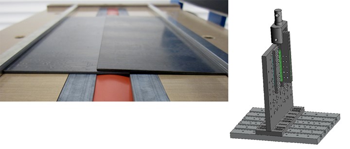
Single lap shear coupon from UD tape laminate ready for induction welding (left) and test fixture for combined shear and peel-off testing of welded L-profile coupon using Rescoll-developed tool (right). SOURCE | KVE Composites, Rescoll.
“The pull-off test method comes from an internal standard that GKN Fokker has developed,” explains Rescoll engineer Thomas Salat. “Pull off testing of the welded profiles is perpendicular to the skin for peel loading,” notes Labordus, “and parallel to the skin for shear load. Peel and shear are the two extremes, but we will also test new combinations of these that reflect practical, in-service load conditions.” This testing will be completed for two distinct laminate thicknesses derived from the MFFD fuselage design — 2.2 and 2.8 millimeters — at room temperature (RT), cold temperature (-55°C) and high temperature (80°C) using static loading.
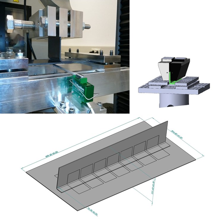
Pull-off tests on L-profile coupons at KVE Composites (top left). In MECATESTERS, this type of testing will use a gripper and test setup developed by Rescoll to eliminate skin deflection (top right). Test coupons will be cut from welded panels (bottom). SOURCE | Rescoll, KVE Composites.
Surface preparation, aging and fatigue
WP 1 will begin with toughness testing. “For the fissurization testing (GIC and GIIC), we will initiate a crack in the composite and measure how this crack behaves when loaded,” explains Salat. “One is a static test that increases load until failure. We will also do a dynamic test where we repeat the static load one million times, which takes one to two weeks to complete. We will see if the composite weld can withstand this fatigue. This mode II is a new kind of cyclic test. We are developing a method taken from a technical paper published by the University of Europe and finalizing the parameters now.”
Also in WP 1, the welding parameters established in WP 2 will be used to examine the effects of surface preparation as well as aging and fatigue. “We will look at surface contaminants and how those may affect the weld,” says Labordus. “We will also investigate three different types of release agents used commonly in press and autoclave processing; specific types of surface preparation including sanding, abrasives and plasma treatment; and also use of an extra resin film at the surface being welded. In addition, we will study the influence of fiber orientation, for example plus/minus 45 degrees at the weld interface.”
Rescoll will also use a conditioning chamber at 70°C and 90% humidity to simulate in-service aging, says Salat. “We will then perform the standard tests to see if it affects the weld performance.” Labordus adds that a limited number of samples will be taken to 100°C and 120°C, “to validate the claim that thermoplastic composites don’t have a sharp knockdown above 80°C.”
In addition to the dynamic fissurization/GIIC test, fatigue testing will be performed in single lap shear and pull-off modes. “We will start at 80 percent of the static failure load and go to 50 or 75 percent of this in fatigue for a million cycles,” says Labordus. “We will do other tests as well but are still discussing these,” adds Salat.
Welding to short compound brackets
Though the details of WP 3 are still being finalized, it is aimed at investigating welds of compression molded brackets made from short fiber material to the UD laminate skin. “We will again benchmark process parameters and characterize the mechanical properties of the weld,” says Labordus, “but we are still working to define the geometry for testing.”
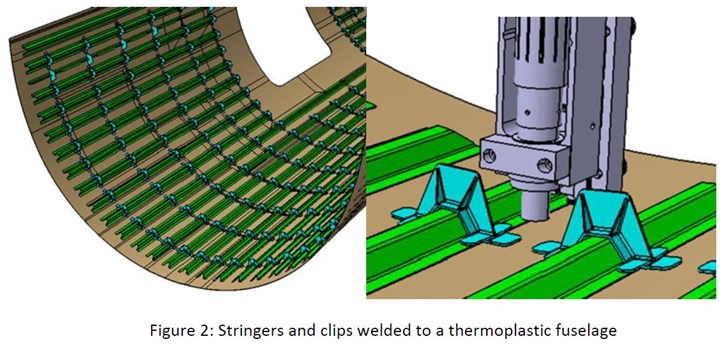
Stringers and clips welded to a thermoplastic fuselage. SOURCE: Clean Sky 2 11th Call for Proposals JTI-CS2-2020-CfP11-LPA-02-35, “Innovative disbond arrest features for long thermoplastic welded joints”, Figure 2, p. 94.
Welded clips and brackets
As outlined in the CFP10 topic JTI-CS2-2019-CfP10-LPA-02-31, all of the frame clips and system brackets for the MFFD lower fuselage will be manufactured via injection molding of short-fiber compounds made by reusing factory waste from the topic manager GKN Fokker’s production of continuous fiber TPC laminates. CF/PAEK is the baseline material and welding is the baseline joining method, though the specific welding method is not prescribed.
According to the CFP10 text, the MFFD lower fuselage will have 13 frames and about 36 stringers, requiring roughly 500 frame clips (note these are primary structures requiring structural tests and this total includes clips used for testing) and approximately 270 system brackets (which are secondary structures) split per the types shown below: 20 system brackets (1), 120 system brackets (2), 50 system brackets (3) and 80 system brackets (4).
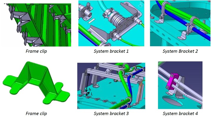
Examples of parts to be delivered in Clean Sky 2 topic JTI-CS2-2019-CfP10-LPA-02-31, Figure 2. SOURCE | Clean Sky 2 CFP10, p. 146.
Also in CFP10 is the MFFD upper fuselage topic JTI-CS2-2019-CfP10-LPA-02-30, “Development of innovative welding systems for structural joints of Thermoplastic matrix-based Composites” led by Aernnova Composites Illescas (Illescas, Spain). Slated to begin after 1Q 2020, its scope is to develop a welding system to achieve a structural bond between reinforcement parts (gussets, wedges, fittings) and structural frames to obtain a highly integrated Door Surround Structure (DSS). I hope to give more details on the MFFD upper fuselage in a future blog. For now, it’s enough to understand why the MECATESTERS work package 3 is important and how much will be achieved once MECATESTERS, STUNNING and the MFFD are completed.
Joining the two halves
Once completed, the lower half of the MFFD will go to Fraunhofer Institute for Manufacturing Techanology and Advanced Materials IFAM (Stade, Germany) to be joined with the upper half, Veldman explains. “We are committed to deliver our half of the fuselage by the end of 2021,” he adds.
As noted above, Ralf Herrmann at Airbus is the MMFD project leader; thus, Airbus integrates the work of Fraunhofer IFAM and the CFP07 MultiFAL (Multifunctional automation system for Fuselage Assembly Line) consortium —which is in charge of joining the two fuselage halves, working together with the STUNNING and upper fuselage teams —to develop solutions for the myriad challenges.
Some of these are revealed within two topics in the 11th Call for Proposals (Nov 2019), both led by Airbus to begin after Q4 2020 and titled “Tooling, Equipment and Auxiliaries for the closure of a longitudinal Barrel Joint:”
- JTI-CS2-2020-CfP11-LPA-02-33, “:Butt strap integration and Lightning Strike Protection continuity”
- JTI-CS2-2020-CfP11-LPA-02-34, “:Overlap joint and Frame Coupling integration”
Written by Piet-Christof Woelcken, topic manager at Airbus Bremen and MFFD work package leader, the main challenges in these topics include:
JTI-CS2-2020-CfP11-LPA-02-33
- Butt strap joint (Fig. 3 below):
- The demonstrator’s left-hand side (in flight direction) includes the Passenger Door Surround. The skin thickness variation in this area necessitates a stepped butt strap integration, joining upper and lower skins.
- Given the joint complexity, conduction welding using a heated pressure plate is the preferred joining technology.
- Electrical continuity of the lightning strike protection (Fig. 4 below):
- Electrical continuity of the metallic lightning strike protection (LSP) must be achieved across both longitudinal joints on the outside of the fuselage.
- It is expected that the tooling head provided for the butt strap integration may be used for this purpose.
JTI-CS2-2020-CfP11-LPA-02-34
- Overlap joint (Fig. 2 below):
- The 8-meter-long overlap joint on the demonstrators’ right-hand side (in flight direction) connects the upper and lower fuselage skins. In a longitudinal direction, skin thickness below 3mm is constant in the welding zone. In the circumferential direction, skins feature a stepped geometry for improved structural performance.
- Ultrasonic welding is the preferred joining in order to achieve high production rate.
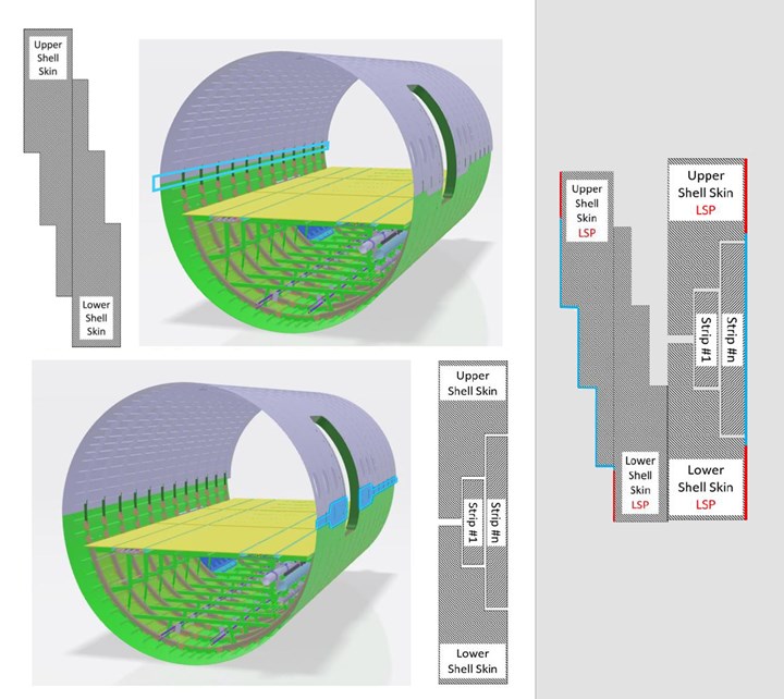
Fig. 2 (Top Left): Overlap joint: A stepped approach has been taken in the overlap joint design. Note that the lower shell lies on the inner side of the fuselage. Fig. 3 (Bottom Left): Butt strap integration: A number of overlying strips require integration across the stepped joint. Note that the Butt strap sits on the outside of the fuselage. Fig. 4 (Right) : Electrical continuity of metallic LSP must be achieved across the longitudinal joints on the outside of the CFRP fuselage. Red indicates pre-equipped LSP, blue indicates LSP to be applied as part of this topic. SOURCE | Clean Sky 2 11th Call for Proposals JTI-CS2-2020-CfP11-LPA-02-33 and -34, “Butt strap integration and Lightning Strike Protection continuity”, pp. 78 and 86.
JTI-CS2-2020-CfP11-LPA-02-34
- Frame coupling integration (Fig. 5):
- Overlap joint: Frame couplings beneath the overlap joint need to structurally bond the upper and the lower shell frames.
- Butt strap: Frame couplings beneath the butt strap need to structurally bond the upper and the lower shell frames as well as connect to the skin.
- Resistance welding is the preferred technology for this technical challenge.
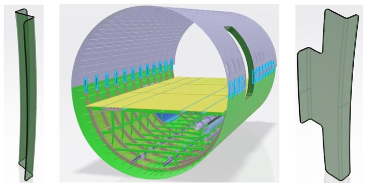
Frame coupling integration. Note that frame couplings differ per side as part of the technology demonstration. SOURCE | Clean Sky 2 11th Call for Proposals JTI-CS2-2020-CfP11-LPA-02-34, “Tooling, Equipment and Auxiliaries for the closure of a longitudinal Barrel Joint: Overlap joint and Frame Coupling integration”, Fig. 5, p. 86.
Welding methods, tooling heads and tolerances
Herrmann explains that conduction welding will be demonstrated on the left-hand side via the butt strap joint and ultrasonic welding on the right-hand side via the overlap joint while resistance welding will be used for the frame couplings. “MFFD will demonstrate many technical approaches, so it is not the same as in manufacturing an actual fuselage, but instead is designed as a vehicle for demonstrating and maturing technologies,” he adds.
Developing welding tooling heads
The objective of these two topics written by Woelcken is to develop the required tooling heads for these welded joints. “When you weld two pieces together, you must apply heat and pressure,” he explains. “So, this is applied by the tooling head during welding. For the Fokker-type conduction welding process, you actively apply heat and pressure on one side and passive pressure from a support is exerted on the other. The butt joint is a stack of six tapes, and in joining, we will place the stack and heat it during welding. However, because the LM PAEK UD tape material is relatively new in welding, we must understand the process conditions and how we can compensate for tolerances. So, we must define the materials and thickness, as well as the geometry of the tooling head.”
“Note that using this type of butt joint is a standard process for what we’re doing on other joints in our aircraft,” Woelcken points out. “For the MFFD, we want to leave the upper and lower fuselage unchanged from this standard practice in order to minimize the amount of material that we have to tailor.”
Flexibility in tolerances
Woelcken notes that because the topmost welding surfaces are essentially melted into liquid and then pressed together, “this gives a lot of flexibility to accommodate for tolerances.” Note, currently, with thermoset carbon fiber reinforced polymer (CFRP) wings and fuselages, these tolerance issues are addressed by applying a liquid shim adhesive. Though few people want to discuss this publicly, the general issue of shimming in composite aerostructures has been widely acknowledged and initiatives to reduce and/or eliminate it have been publicized, such as the Flexmont assembly method for vertical tail planes.
“We do expect to gain advantages in addressing tolerances by using thermoplastic composites,” says Woelcken, “particularly by exploiting our design concepts and drawing on our experience with thermoset CFRP and metallic welding. The key will be in situ monitoring during heating and application of pressure.” He stresses that heat is the number one parameter. “I’m surprised how tolerant the thermoplastic composite welding processes are to pressure. The main challenge there is containment of that pressure and how it drops off. Currently, we are monitoring the back side of the welded joint.”
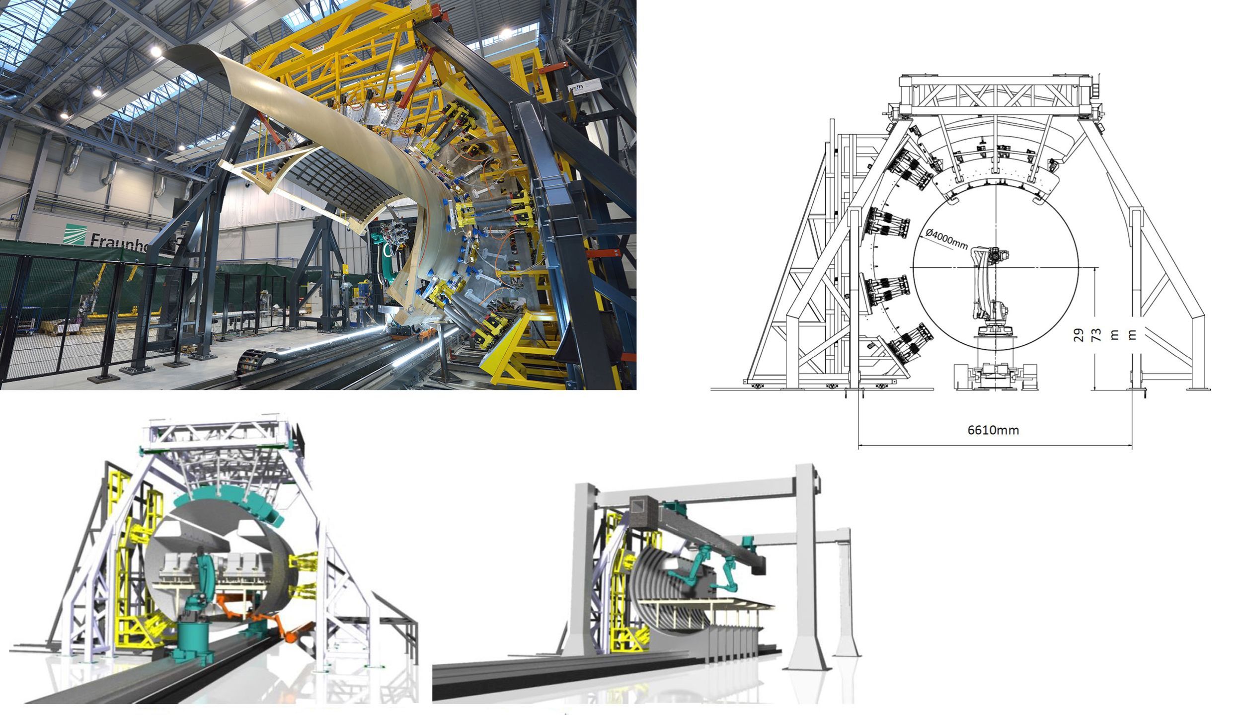
Fraunhofer IFAM automated assembly plant system (top left) with dimensions at beginning of CFP07 work topic (top right) is being modified to accommodate a 360° fuselage for welding the MFFD’s longitudinal and circumferential joints. SOURCE | Fraunhofer IFAM and cfk-valley.com, Clean Sky 2 7th Call for Proposals, JTI-CS2-2017-CfP07-LPA-02-22, p. 76.
Assembly automation
In the 7th Call for Proposals, the topic JTI-CS2-2017-CfP07-LPA-02-22, “Development of a full-size, automated plant system for fuselage longitudinal and circumferential joints” is led by Fraunhofer IFAM within the MultiFAL consortium. The excerpt below sheds some light on how the welding tooling heads discussed above, now in development, might be implemented:
“To realize the assembly process of a thermoplastic fuselage, tolerances become a major topic. The positioning and orientation of the fuselage shells, as well as resulting deformations caused by the welding process, need to stay within the tolerances. Comparable accuracies can be oriented to the state-of-the-art process of longitudinal joint. Here, the position error in each direction should be within 0.5 mm (in some exceptions up to 1 mm). … it can be assumed that a pre-load on the joint surface from both sides of approximately 1000N (independent of the welding technology) for a welding seam of 20 mm width is required by the automation system.”
Fraunhofer IFAM — which was also CTC Stade’s partner in developing the Flexmont VTP assembly process — describes its starting point: an in-house assembly plant system which can manipulate parts from 2 to 8 meters long and up to 6 meters high, including a 180° shell of a single-aisle aircraft. The system is enabled by a flexible arrangement of 10 cooperating hexapods (see “Reconfigurable Tooling: Revolutionizing composites manufacturing”), 24 linear units and modular rack elements. Vacuum grippers with 6-axis force and torque sensors adjust the pose and shape of the part, as required, to manage tolerances during assembly. The guidance and monitoring of these rapid, iterative adjustments is achieved through optical measuring devices.
According to the CFP07 text, Fraunhofer IFAM will modify this assembly plant system for holding a complete 360° fuselage, with work scheduled to begin in Q2 2018 and completed in 36 months.
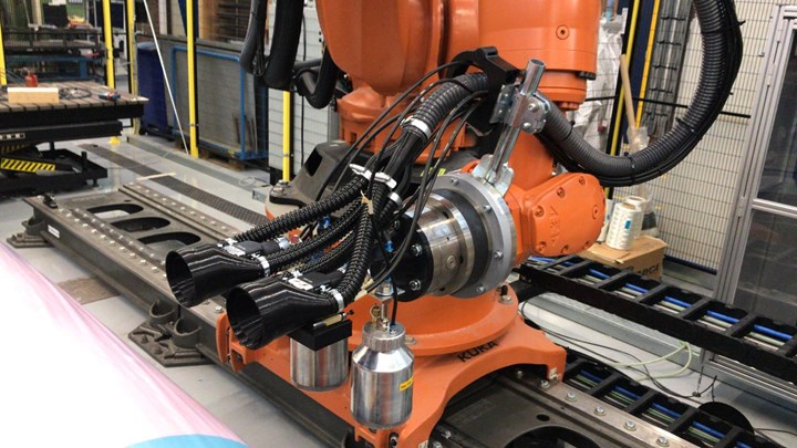
The STUNNING consortium is working with SAM|XL to develop automation for assembling the MFFD lower fuselage. SOURCE | samxl.com
Within STUNNING, activities are planned with the collaborative research center SAM|XL (Smart Advanced Manufacturing XL, Delft, Netherlands) to demonstrate automated welding techniques for assembling the lower fuselage. Specializing in automation for manufacturing large, lightweight composite structures, SAM|XL brings together TU Delft’s Aerospace Engineering group and Robotics Institute. GKN-Fokker is a major participant. One of the methods being investigated is sequential spot ultrasonic welding, which was proven in the Clean Sky 1 Eco Design project and TAPAS 2 as a fast and effective for connecting short fiber-reinforced brackets or clips to fuselage structures.
In her 2016 paper, titled “Smart ultrasonic welding of thermoplastic composites,” Villegas states that it is possible to scale up the ultrasonic welding process via sequential welding — that is, letting a continuous line of adjacent spot welds serve the same purpose as a continuous weld bead. Lab-scale sequential spot welding was used in the Clean Sky EcoDesign demonstrator’s TPC airframe panel, using flat energy directors to weld a CF/PEEK hinge and CF/PEKK clips to CF/PEEK C-frames (Fig. 6). Experimental comparisons with mechanically fastened joints in double-lap shear and pull-through tests showed promise. The process is further explored in 2018 papers {and 2019 papers} by Villegas’ TU Delft team member Tian Zhao {and in Villegas’ 2019 paper}.
— “Welding thermoplastic composites”, G. Gardiner, 2018.
The STUNNING consortium’s work with TU Delft and SAM|XL is adapting this technology to weld multiple system and semi-structural brackets, stiffening elements and stringers to the MFFD lower fuselage shell.
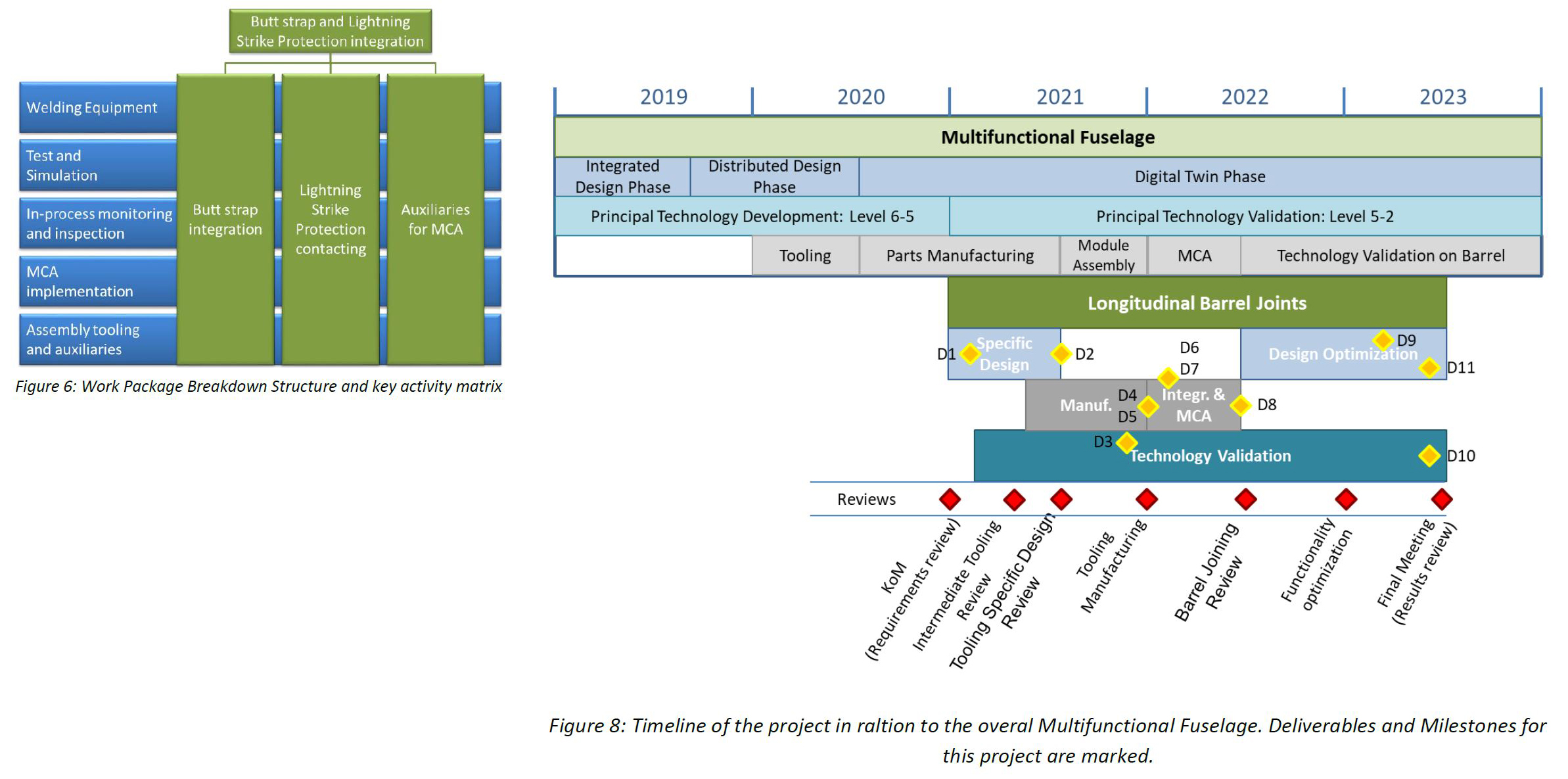
Work breakdown and timeline for MFFD assembly. SOURCE | Clean Sky 2 11th Call for Proposals JTI-CS2-2020-CfP11-LPA-02-33, “Tooling, Equipment and Auxiliaries for the closure of a longitudinal Barrel Joint: Butt strap integration and Lightning Strike Protection continuity”, pp. 79 and 82.
Digital twin phase, 2020 and beyond
According to the Clean Sky website, the MFFD program reached an important milestone in Nov 2019 with the successful passing of its Critical Design Review (CDR). In the timeline above, the MFFD design enters a “Digital Twin Phase” in 2020-2021. What does this mean? “Though we have wrapped up the majority of the design phase, we are taking it a bit further by working with a specific lifecycle management approach,” explains Herrmann. “We are modeling imperfections and nonconformities from the NDT results and process parameters during component manufacturing. We want to combine this Industry 4.0 data with lifecycle management so that we continue to tailor the design according to what we are actually manufacturing. We want to see how far we can push this and what we can accomplish by the end of Clean Sky 2.”
For 2020, the chief agenda is manufacturing. “We hope to present various parts as they come together this year,” says Veldman. What will the largest challenge be for the STUNNING program? “Assembly,” he answers. “Not so much within STUNNING, but our lower fuselage has interfaces with the door surround structure, multiple Airbus-delivered components and the whole upper fuselage. Getting everything delivered at the right time and then bringing it all together will require a number of developments yet.”
That brings us to perhaps the biggest question: Will thermoplastic composites be used on the next aircraft entering production in 2030-35? “For sure, we want to try to use the technologies we are working on,” says Herrmann, “but I cannot say if or when thermoplastic composites will be on future aircraft. The most important part for us is that they are an enabler for dustless joining regarding ramping production to more than 70 aircraft per month. We have to show that it is feasible, not only with metallics but also with thermoplastic composites.”
“By the end of this project, we will have a more complete understanding of thermoplastic composite welding and will gain approval for its use in large primary aircraft structures,” says Salat. “If we can use this for future aircraft, we can achieve significant weight savings and improved sustainability.” But perhaps just as important is Clean Sky’s ability to bring Europe’s aviation research and innovation stakeholders closer together. “We have quarterly meetings where I sit with all of the LPA steering committee,” says Veldman. “I’m talking to the whole of the European aerospace industry, and it most certainly helps to open up opportunities for the future, not only for companies who can supply to us, but for a wide range of collaborations.”


Related Content

Automated robotic NDT enhances capabilities for composites
Kineco Kaman Composites India uses a bespoke Fill Accubot ultrasonic testing system to boost inspection efficiency and productivity.
Read More
NDT inspection services, automated systems serve aerospace needs
CAMX 2023: Arcadia Aerospace Industries demonstrates its commitment to navigating the rapidly changing aerospace manufacturing landscape with robotic-based machines and motion control systems, certified facilities for NDT services and conducted training and recruitment.
Read More
Xnovo Technology, Exciscope introduce X-ray tensor tomography technique
Through a strategic partnership, the companies introduce the FiberScanner3D module, dedicated to bringing more rapid, reliable and robust fiber structure characterization methods to lab settings.
Read More
Acoustic imaging enables vacuum leak detection
CAMX 2023: Distran is demonstrating how its ultrasonic camera technology rapidly locates leaks during the vacuum bagging process, and reconstructs their position in real time.
Read MoreRead Next

First Toray LM-PAEK laminate for Clean Sky MECATESTERS project
KVE Composites Group and Rescoll cooperate in GKN Fokker-led project to develop micromechanical characterization of thermoplastic co-consolidated joints for aircraft fuselages
Read More
Welding thermoplastic composites
Multiple methods advance toward faster robotic welds using new technology for increased volumes and larger aerostructures.
Read More
Thermoplastic composite demonstrators — EU roadmap for future airframes
There is a TPC development roadmap in Europe, supported by Airbus and a variety of aerospace consortia, and involving almost every major aerostructures supplier in Europe.
Read More