


Demonstrating welded thermoplastic composite (TPC) patch repair
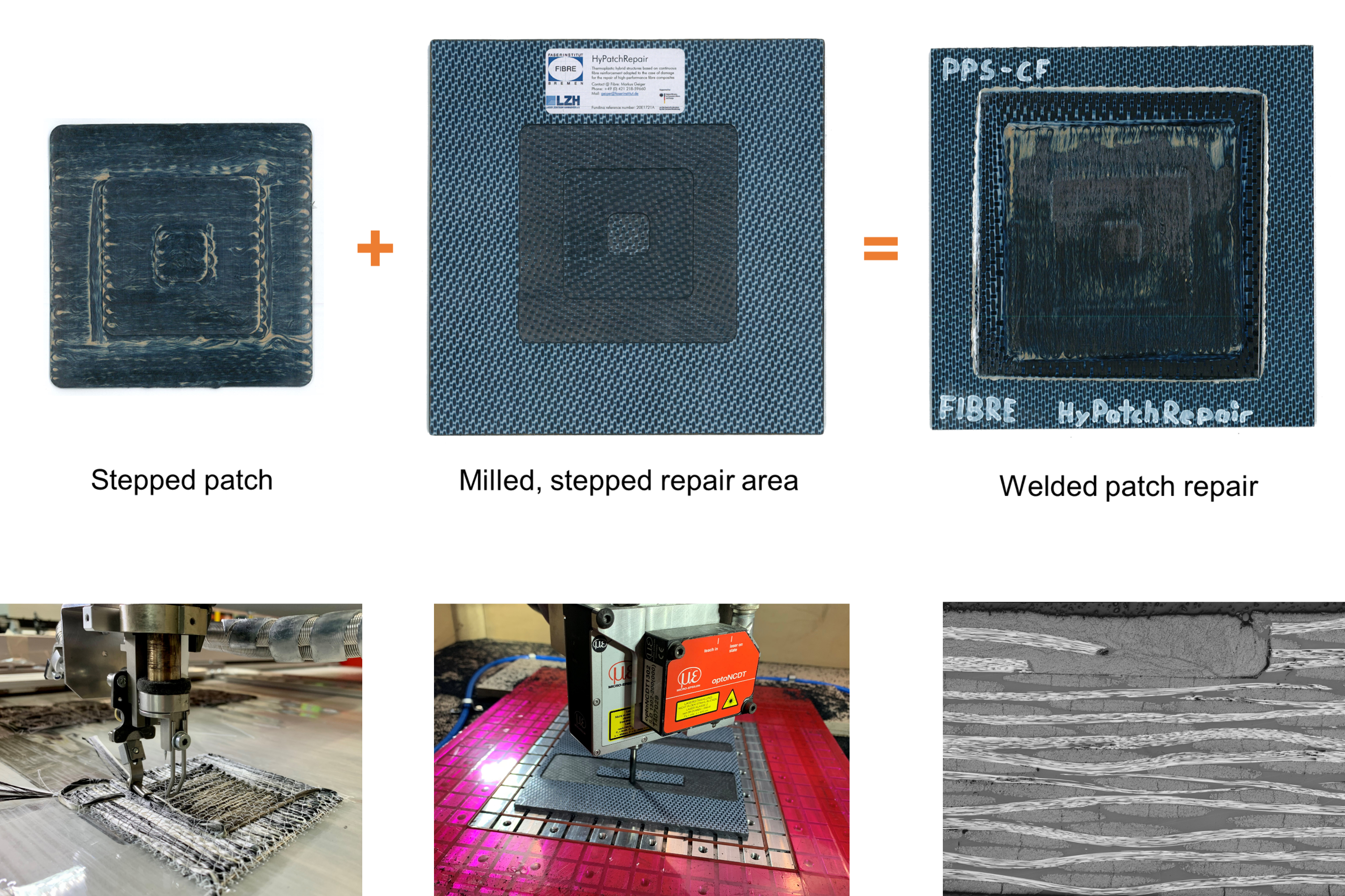
The HyPatchRepair project (from left to right, top and bottom images) paired a stepped repair patch made using tailored fiber placement (TFP) with a milled panel of the same construction and integrated them using press welding to demonstrate the feasibility of an automated TPC repair process chain (see welded patch at top of micrograph). Photo Credit: HyPatchRepair project, Faserinstitut Bremen
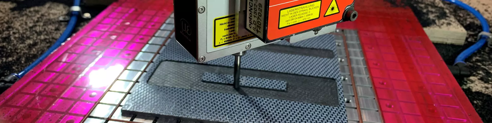
Image at top, in line with title: A DMG Mori Ultrasonic MobileBLOCK robot mills a repair area into steps, after which an integrated Wenglor laser profile scanner will measure the surface for accuracy. Photo Credit: HyPatchRepair project, Faserinstitut Bremen
Thermoplastic composites (TPC) continue to be demonstrated in ever larger aircraft structures, offering fast manufacturing to meet increased production rates anticipated for future narrowbody and advanced air mobility (AAM) platforms. TPC structures also enable welded assemblies, eliminating fasteners, which further reduces production time, cost and weight. In a recent blog, Tier 1 aerostructures supplier Spirit AeroSystems (Wichita, Kan., U.S.) explains, “using thermoplastics in larger components, like stringers, frames, bulkheads and fuselage skin panels, can be incredibly beneficial. We aim to utilize thermoplastic composites in applications where automated high-rate manufacturing is possible … repeatedly melting, forming and solidifying material in very short cycle times.”
However, aircraft in use get damaged, and that damage necessitates repair. Repair techniques for thermoset composites are well developed, including the common method of restoring even primary structures using a bonded composite repair patch (see “A second look at cobonded tapered scarf repairs for composite structures”). Although TPC structures have flown since the 1990s, similar repair techniques are still in development.


The HyPatchRepair project (2019-2022) was funded by the German government — as part of the LuFo-V3 aerospace research program — to demonstrate rivet-free repair technology for continuous fiber-reinforced TPC parts. The goal was a set of automated repair techniques to restore the original load-carrying capacity, geometry and aerodynamic surface without adding weight for parts such as fuselage skins, wings, winglets and empennage components, including rudders. These techniques would prepare the repair area, fabricate a load-optimized repair patch and then integrate the patch into the repair area using proven and cost-effective technologies.
Automated repair process chain
The German HyPatchRepair consortium was led by research institutes Faserinstitut Bremen (FIBRE, associated with the University of Bremen) and Laser Zentrum Hannover (LZH, Hannover). The project included Airbus Operations, aircraft repair services provider Lufthansa Technik (Hamburg), small aircraft manufacturer Silence Aircraft (Schloß Holte Stukenbrock) and optical measurement systems supplier Vereinigte Elektronikwerkstätten (VEW, Bremen) as associated partners. Due to its expertise in large TPC structures, GKN Fokker (Hoogeveen, Netherlands) provided defect/damage cases and helped to define demonstrators.
The process chain conceived by this consortium includes:
- Detect damage: An optical measuring system inspects the part to be repaired and determines the area and depth of material that needs to be removed, minimizing this if possible. VEW demonstrated this step using an optical measuring system at its facilities.
- Mill the repair area: Damaged material is removed with a DMG MORI (Bielefeld, Germany) five-axis ULTRASONIC mobileBLOCK robot, providing consistent quality, dimensional accuracy and repeatability. To replace the removed plies with an accurate repair patch, the repair area is machined into steps. FIBRE demonstrated this process using the DMG MORI robot while LZH explored using lasers.
- Measure the repair area: The stepped repair area must be accurately measured to fabricate a precisely fitting repair patch. LZH demonstrated this step using a Wenglor (Tettnang, Germany) MLWL 232 laser profile scanner. LabVIEW software (National Instruments, Austin, Texas, U.S.) was used to convert the data into the required patch dimensions.
- Fabricate repair patches: Repair patch preforms are fabricated using tailored fiber placement (TFP) and continuous fiber 3D printing and are then consolidated. FIBRE demonstrated the manufacturing of TPC preforms and consolidation using a heated press and specially designed tooling.
- Trim patches: The patches are measured after consolidation and compared with the stepped repair surface. Required trimming is completed using a laser, demonstrated by LZH.
- Weld patches: Patches are fused to the repair area using laser beam welding. LZH demonstrated how this method would work while FIBRE demonstrated the concept using pressure welding in a heated press.
Note, HyPatchRepair’s goal was to demonstrate the feasibility of this process chain and complete parametric testing to understand and select the best process options. Materials investigated included carbon fiber (CF)-reinforced polyamide 6 (PA6) and polyphenylene sulfide (PPS). A follow-on project, ThermoRep3D (2022-2025), will further develop these process steps, including manufacture and welding/fusing of curved patches to a curved repair area and use of carbon fiber-reinforced low-melt polyaryletherketone (LM-PAEK) tape materials.
Robotic approach adapted for HyPatchRepair
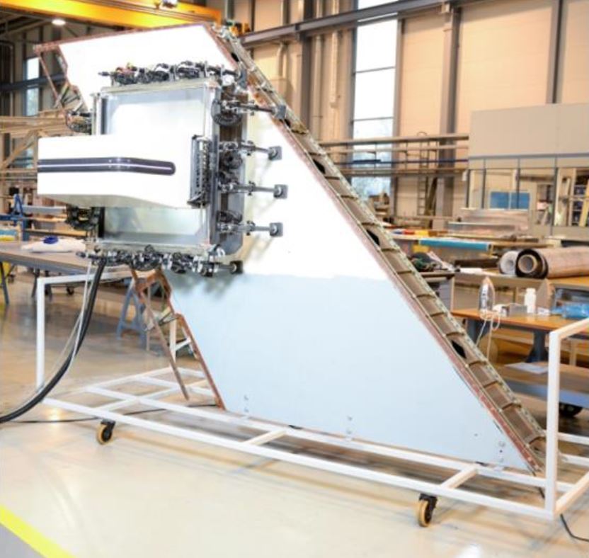
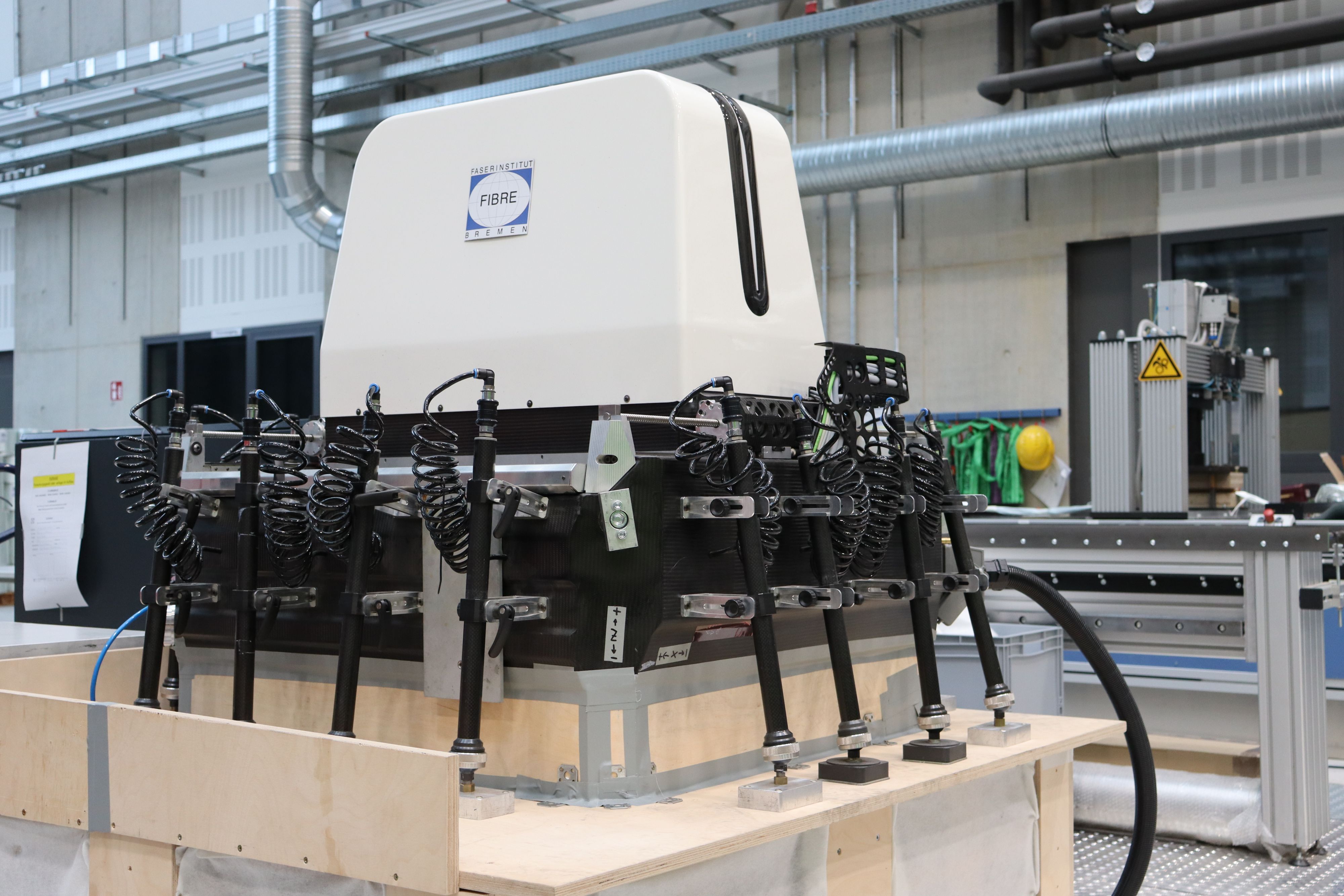
Fig. 1. Adapted robot cell
The DMG MORI robot used in HyPatchRepair shown in testing at CTC Stade on a vertical fin (top) and after modification to perform milling and scanning on flat panels within a temporary plywood cell at FIBRE (bottom). Photo Credit: HyPatchRepair project, Faserinstitut Bremen
Using robots to perform bonded patch repairs was explored 10 years ago with thermoset composites in the Composite Adaptable Inspection and Repair (CAIRE) project (2012-1015) led by Lufthansa Technik and Airbus. The robot developed in CAIRE and the DMG MORI robot above were discussed in CW’s 2016 article, “Aircraft composite repair moves toward maturity.” American GFM (Chesapeake, Va., U.S.) has developed a similar robotic approach (see “Moving toward portable, digitized composite part repair”). The task for HyPatchRepair was how to adapt this process for TPC parts.
The DMG MORI robot was previously located at Airbus’ Composite Technology Center (CTC, Stade, Germany), notes Markus Geiger, HyPatchRepair project manager at FIBRE. “We brought it to FIBRE’s ECOMAT center, next to Airbus Operations in Bremen, and then modified it.” He explains the robot was designed to attach onto the body of an aircraft. But because the trials in HyPatchRepair would be on flat panels, FIBRE created a type of R&D cell within which the robot could perform scanning as well as milling with vacuum dust extraction (Fig. 1). Both operations were possible using a single end effector equipped with a milling tool and laser line scanner (Step 1).
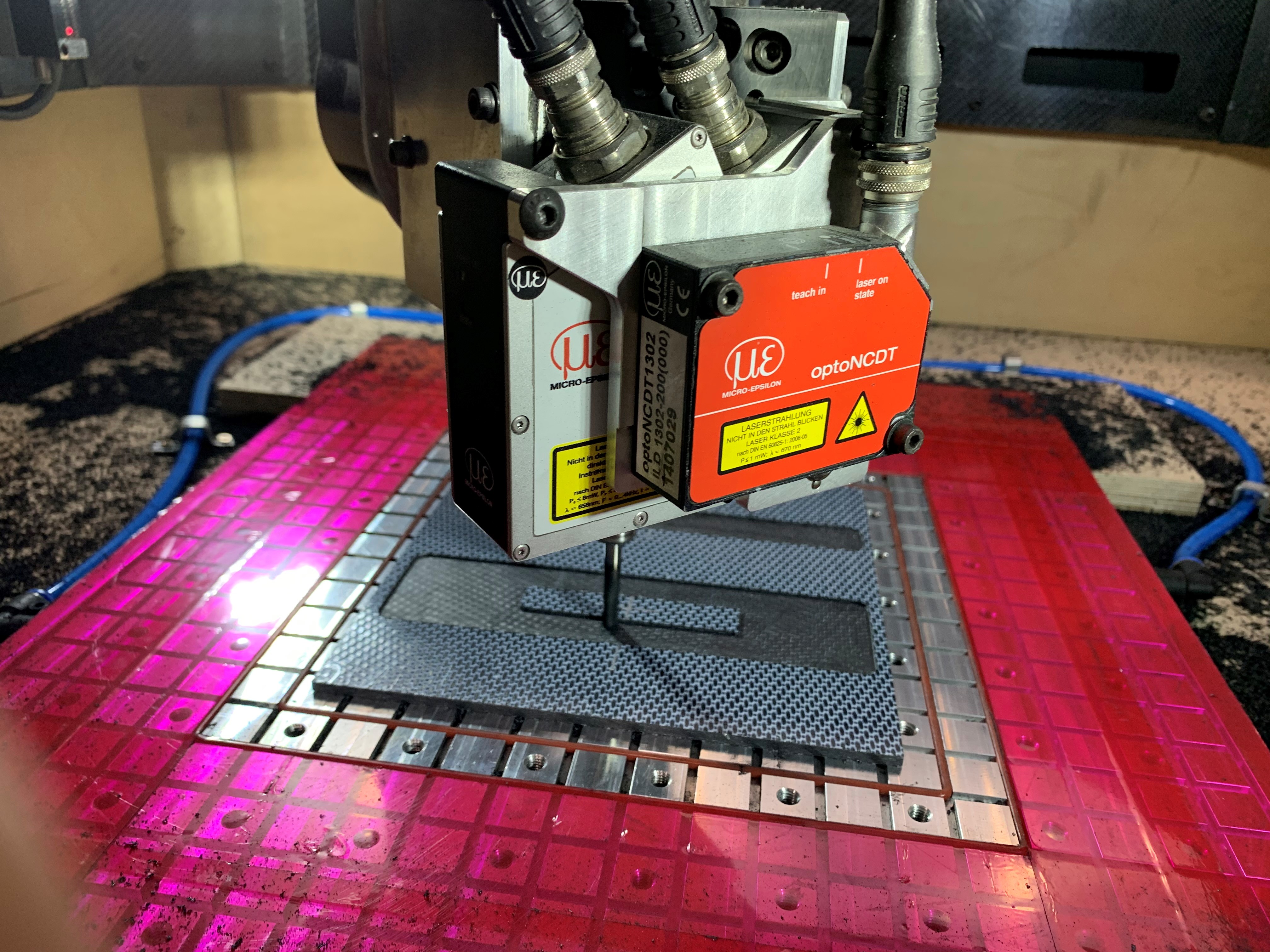
Step 1. Robot mills steps into demonstrator panel. Laser profile scanner also attached to the end effector will scan the machined surface for accuracy. Photo Credit: HyPatchRepair project, Faserinstitut Bremen
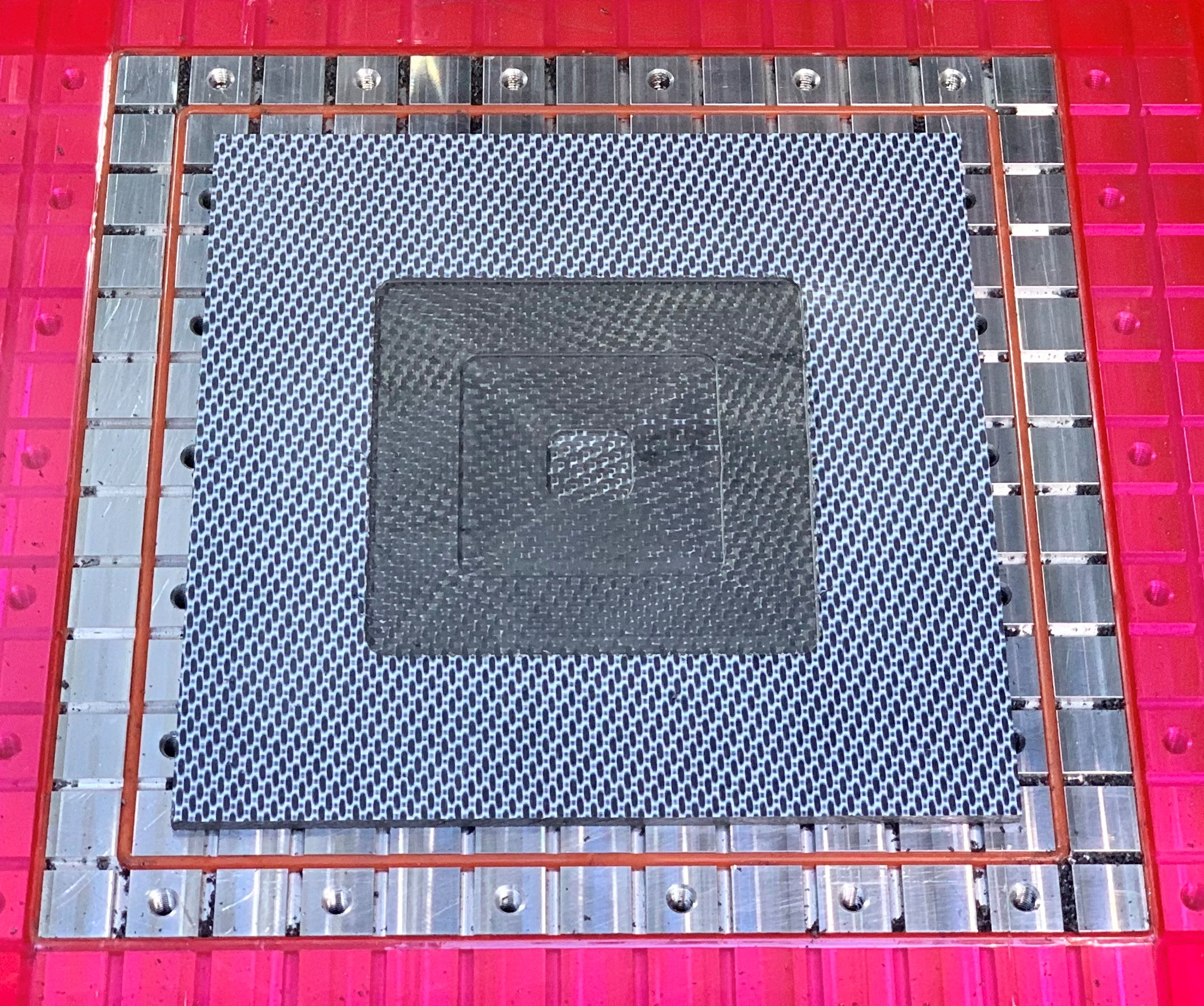
Step 2. Three 20-millimeter-wide steps machined in the repair area are ready to be scanned. Photo Credit: HyPatchRepair project, Faserinstitut Bremen
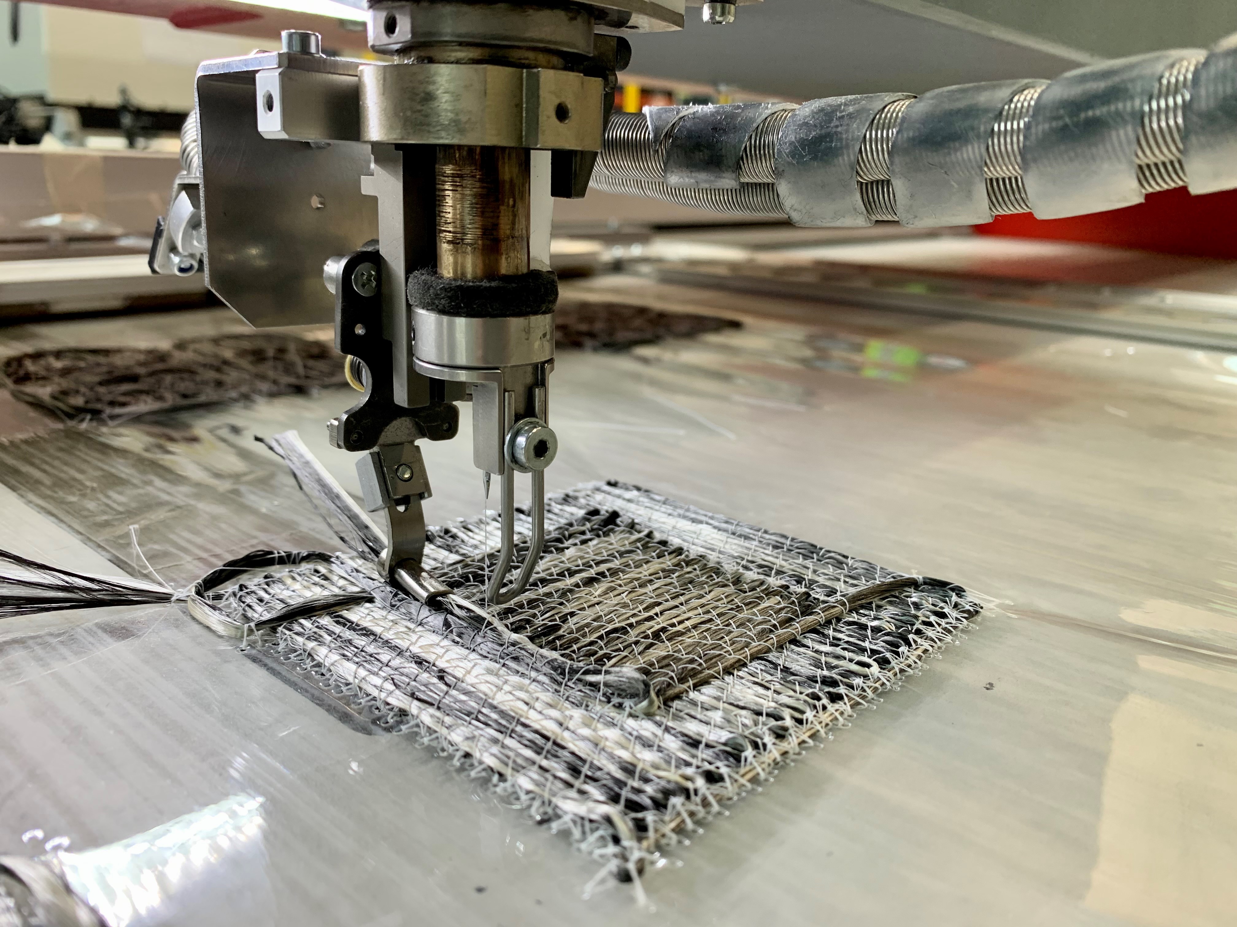
Step 3. Tailored fiber placement (TFP) using CF/PPS fiber produces 100-, 60- and 20-millimeter-wide steps as a single 100 × 100-millimeter repair patch. Photo Credit: HyPatchRepair project, Faserinstitut Bremen
Milling and patch demonstrations
To demonstrate TPC patch repair, HyPatchRepair selected a 100 × 100-millimeter square patch with three 20-millimeter-wide steps. Demonstrator panels had to be manufactured and then milled to match these steps. In an actual repair, the goal is to restore the laminate so that all removed material is replaced, matching the fiber orientation of each ply. The DMG MORI robot was thus programmed to mill a three-stepped area in the demonstrator panels (Step 1). The end effector was rotated, and the robot then scanned the milled area for accuracy (Step 2). Milling and scanning time totaled 30 minutes.
The next step was to manufacture repair patches. Because HyPatchRepair focused on TPC repair, the project veered away from past prepreg-based processes and instead trialed TFP (Step 3) and 3D printing. Both processes can produce a repair patch with tailored geometry and fiber orientation. TFP uses an industrial stitching machine to affix commingled thermoplastic and reinforcing fibers to a matrix-compatible film (see “Drawing design cues from nature … Part 2”). As explained in part 2 of CW’s 2017 feature on automated preforming, FIBRE has a long history working with TFP, including production of load-optimized TPC preforms, which are then quickly compression molded or thermoformed into parts. For each trial, the demonstrator panel and repair patch were made using the same materials and process.
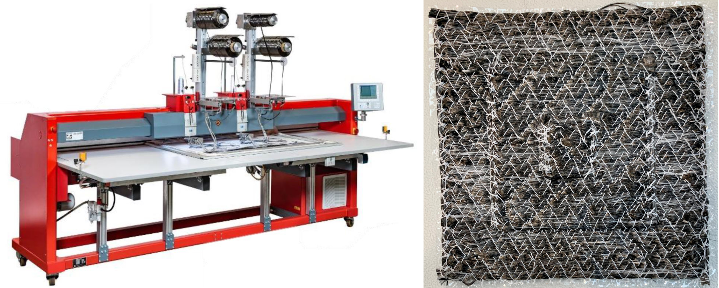
Fig. 2. TFP for TPC patches
A ZSK dual-head stitching machine (left) produced TFP patches (right) using 12K carbon fiber/PPS commingled yarn and higher melt temperature PEEK stitch thread. Photo Credit: HyPatchRepair project, Faserinstitut Bremen
The TFP trials used a dual stitch head ZSK Stickmaschinen (ZSK, Krefeld, Germany) machine and CF yarn commingled with PA6 or PPS (Fig. 2). Ply stacking sequence was 0°/90°/0°/90°/0°/90°. For consolidation (Step 4), each patch was placed into a two-piece steel tool set and thermoformed in a heated press. A typical press cycle for CF/PPS patches included a ramp up to 280°C (10 minutes), a dwell at 280°C for 12 minutes with 30 bar pressure and then a cooldown (10 minutes) while maintaining that pressure. Ply thickness after consolidation was ≈0.25 to 0.30 millimeter. For CF/PA6 patches, a 6- or 8-minute ramp to 240°C was followed by a 10-minute dwell at 240°C and an 8- to 15-minute cooldown. Pressure was stepped from 5 bar during ramp to 10 bar during dwell and to 20 bar during cooldown.
The 3D-printed patches were produced using a Markforged (Watertown, Mass., U.S.) Mark Two machine at CTC Stade and continuous carbon fiber filament in combination with nylon (PA) filament. The ply stacking sequence was 0°/90°/90°/0° per step. Ply thickness after 3D printing was ≈0.10 to 0.125 millimeter. “We had hoped to use continuous fiber filament,” says Geiger, “but due to timing and other factors, this wasn’t possible. The patches as printed still had significant porosity and would require consolidation before being fused with the stepped repair area.” However, by this point in the project, FIBRE had already decided to focus on TFP for patch fabrication.
First trial findings
Geiger discusses various parameters studied during patch fabrication and lessons learned. For example, two approaches were used for the TFP patches, he says, “one where all three steps were one patch and one where we used single patches for each step. In the latter, we cut the 100-, 60- and 20-millimeter-wide steps from a larger TFP sample. This avoids the fiber turnings created at the edges of the patch during the TFP process [see loops at edges of patch in opening image at top].” These turnings tended to create matrix-rich areas, but he notes that cutting the steps from a larger panel created waste.
Step 4. TFP repair patch is consolidated within a two-piece steel tool in a heated press. Photo Credit: HyPatchRepair project, Faserinstitut Bremen
Another finding was revealed during consolidation of the CF/PA6 repair patches. “In these patches, the stitch yarn was also PA6,” says Geiger. “We noticed during the press consolidation that the stitching started to ‘swim,’ meaning it produced areas with more matrix than fiber. So, we then adjusted our approach for the CF/PPS samples, and used polyetheretherketone [PEEK] stitch yarn, which has a higher melting point. When we consolidated these patches, there was no ‘swimming’ and we achieved a better quality.”
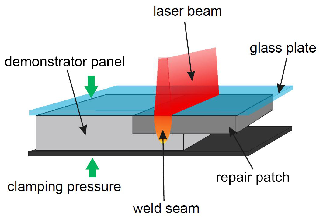
Fig, 3. Laser-based heat conduction welding
A diode laser passes through a glass plate — which maintains pressure on the patch in a welding fixture — and heats up the TPC matrix in the patch and mating stepped surfaces. A reliable weld is created as the materials cool. Photo Credit: Laser Zentrum Hannover
Laser welding
Two welding methods were trialed during HyPatchRepair: laser-based heat conduction welding and press welding, which is discussed below. Laser welding trials were performed by LZH. “The general method used,” explains Verena Wippo, head of composites at LZH, “placed the repair patch and demonstrator panel to be repaired into a welding fixture, which uses a glass plate to press the repair patch down onto the stepped repair area [Step 6]. The laser beam passes through the glass plate and generates heat, which conducts through the repair patch.” This heat melts the matrix in the patch and at the mating surfaces of the stepped repair area. Pressure is maintained, and as the laser passes, and the materials cool, a reliable weld seam is created (Fig. 3).
LZH conducted initial trials using Toray Advanced Composites (Nijverdal, Netherlands) Cetex CF/PPS organosheet, with 10 plies comprising a 3-millimeter-thick demonstrator panel on the bottom and 4 plies used in a 1.2-millimeter-thick repair coupon on top. An additional film of unreinforced PPS was needed in between to provide enough matrix material to ensure a good join between the parts. These materials were heated using a Laserline GmbH (Mülheim-Kärlich, Germany) LDM 300-40 diode laser system with a power of 300 watts, spot geometry of 11 × 40 millimeters and a 940-nanometer wavelength.
Trials then moved to the TFP patches and demonstrator panels. However, there were some initial challenges, notes Geiger. “For example, our patch comprised three steps, each 0.6 millimeter in depth, totaling 1.8 millimeters in thickness. But the laser was only able to weld a 1.6-millimeter thickness. Thus, LZH had to split the welding process into three heating steps, welding each of the three patch plies separately.”
This was solved by implementing a control system that uses a pyrometer to measure the surface temperature. “During several tests, LZH measured the surface temperature as well as the laser power and irradiation time used,” says Geiger, “and compared these with analysis of the welds produced. Using these results, LZH was able to adjust the weld parameters based on the pyrometer measurements. Finally, both multistage welding of each step layer and welding of the complete patch in one pass was achieved.”
The latter was used for the final demonstrator, discussed below. LZH irradiated the entire repair patch area simultaneously in one pass, managed by an automated control system. This system used the pyrometer-measured surface temperature signal, which it processed using a PID (proportional–integral–derivative) controller that then managed the laser power to maintain a specified welding temperature.
Another development was to replace the PPS film with waste from milling the repair steps in the demonstrator panel. “We used that waste to make a small foil, which was laid into the stepped repair area as a first binding ply,” explains Geiger. “This ply was then followed by the patch. This is what LZH did because they needed more matrix to weld the patch using their laser process. And this reused waste actually performs better than a pure matrix foil because it has bits of carbon fiber in it.”
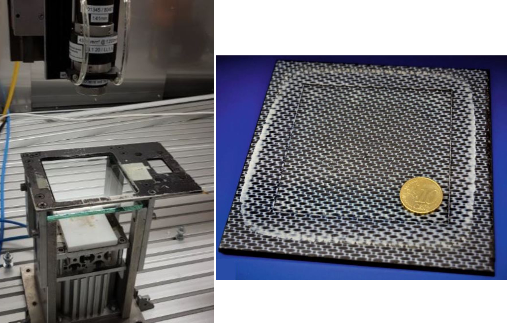
Step 5. TFP repair patches were laser welded to demonstrator panels using a diode laser system and welding fixture (left). The finished repairs showed overall good quality, with no major voids and each step of the repair joined to its matching substrate (right). Photo Credit: HyPatchRepair project, Faserinstitut Bremen
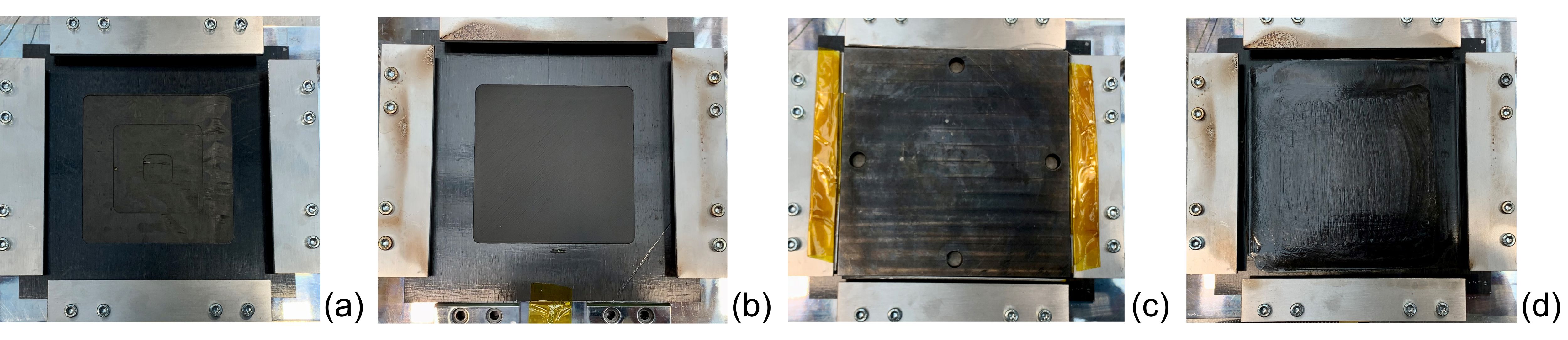
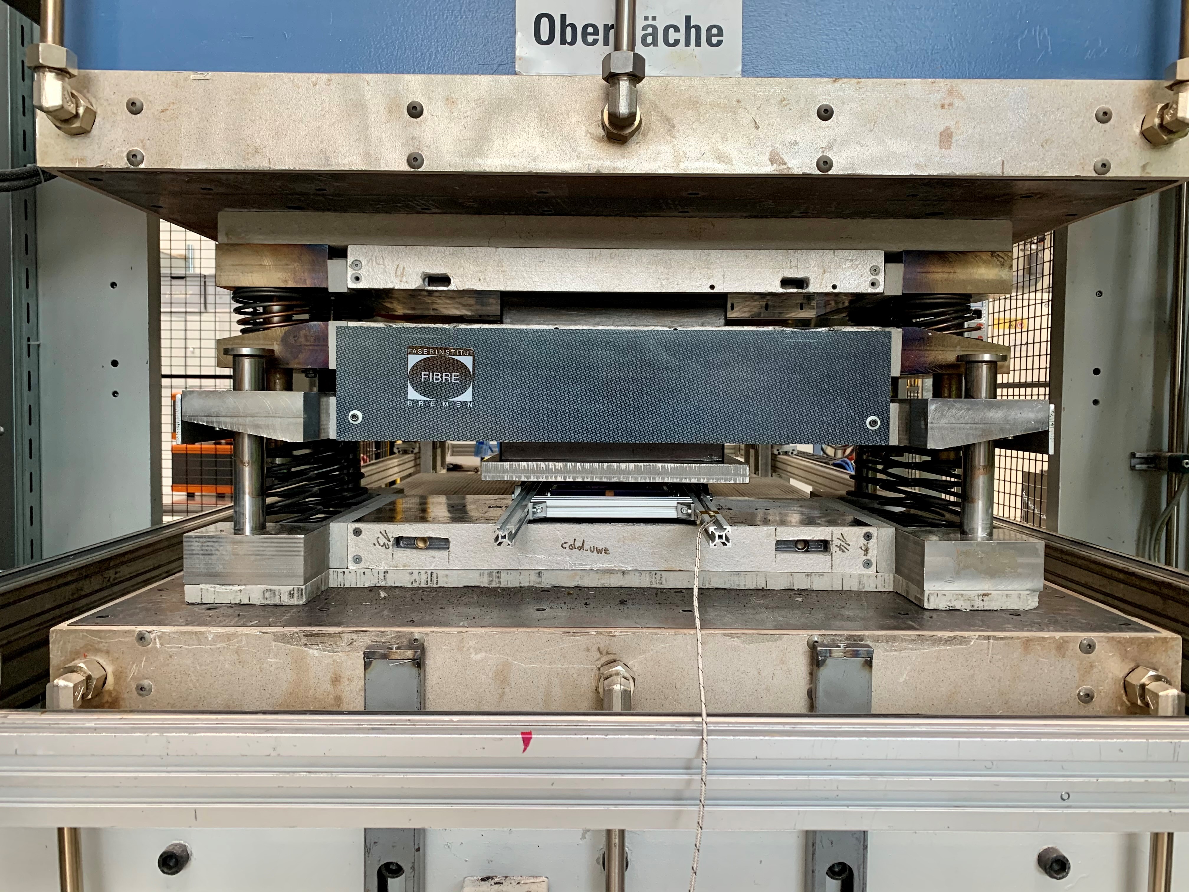
Step 6. Using the tooling in Fig. 4 below, TFP repair patches were press welded to demonstrator panels: (a) Stepped panel in press welding tool; (b) Repair patch matched to stepped panel; (c) Tool closed; (d) Tool opened to show welded repaired panel. Photo Credit: HyPatchRepair project, Faserinstitut Bremen
Press welding, final demonstrator
Press welding was chosen by FIBRE as a method to test materials, process parameters and requirements for achieving a good weld between a repair patch and a stepped repair area. This method was developed during trials of the final demonstrator panel and used to produce more than 30 press-welded demonstrator repairs.
The repair patch size and geometry in the demonstrator remained unchanged from the initial trials, while the panel size was roughly 160 × 160 millimeters to provide post-repair coupons for tensile and three-point bending tests. TFP was selected as the preferred process due to ease of the process, good results during development and availability of in-house equipment. The final material used was Coats (Bristol, U.K.) Synergex 12K CF/PPS commingled yarn partially stitched onto a PPS film Rayotec S 080 PPS film (Toray Advanced Composites) with a PEEK stitch yarn.
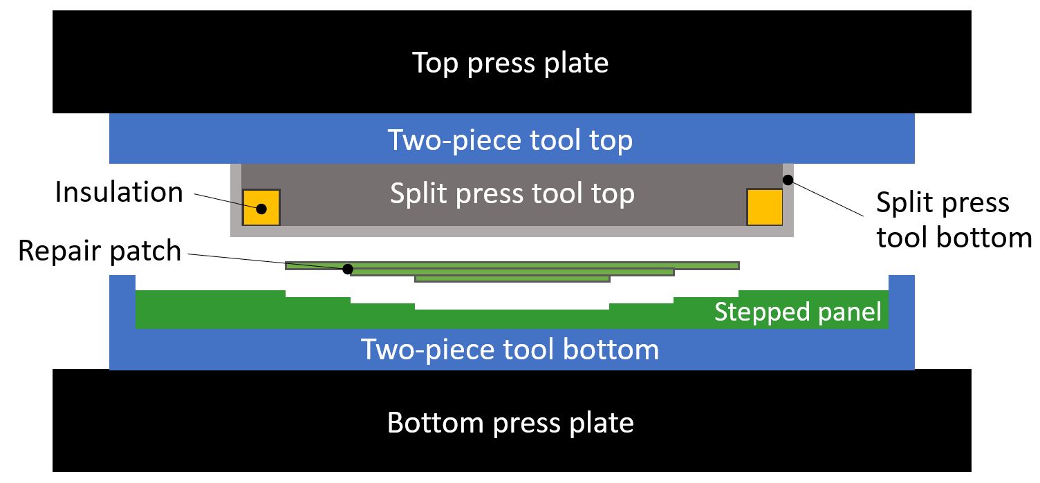
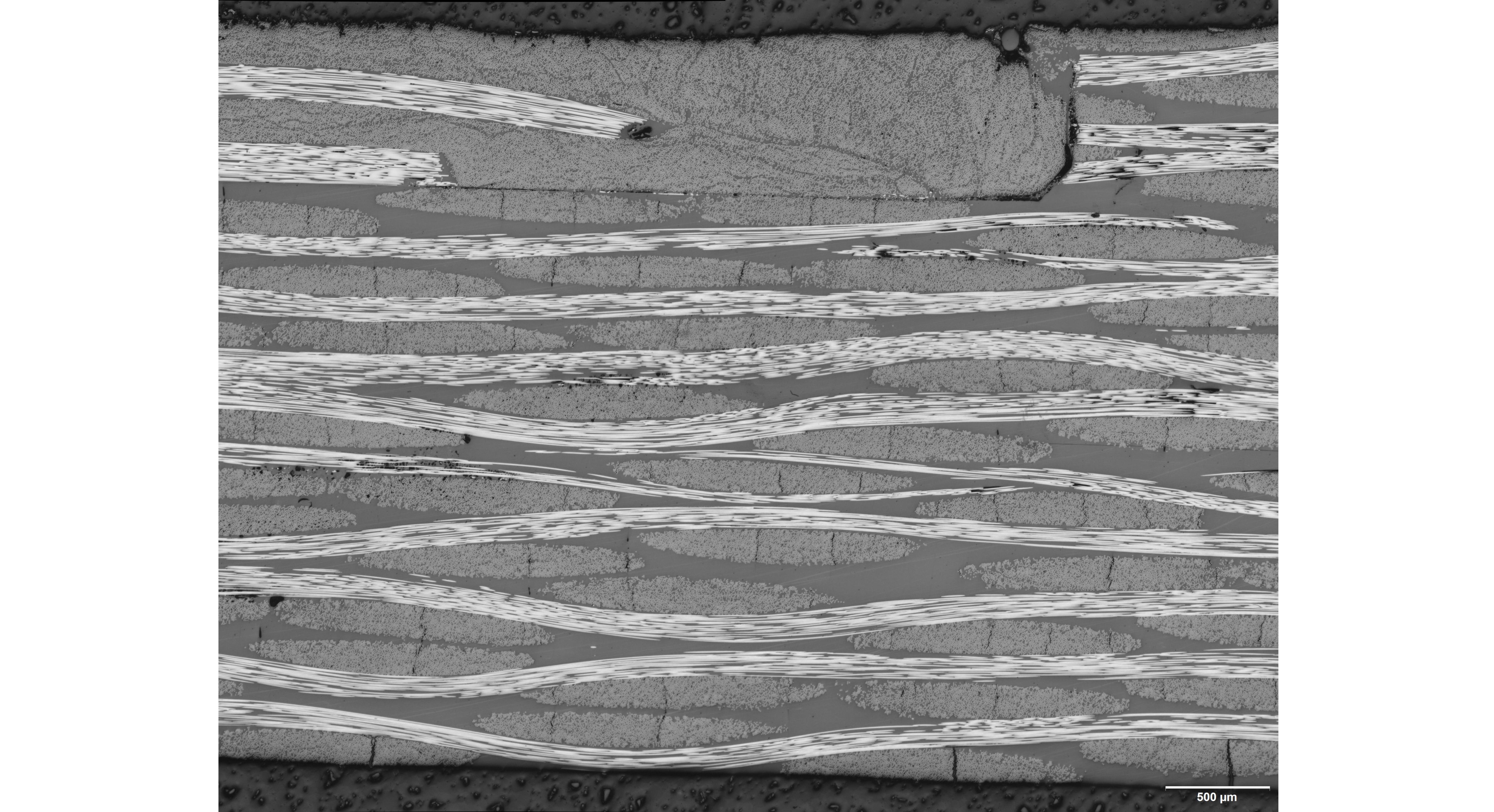
Fig. 4. Press-welding tools, results
To confine heat and pressure to the repair patch during press welding, an additional split press tool was used in combination with the two-piece tool from patch consolidation (diagram at top). Cross-section micrographs at the outer edge of the repair patch show the welded patch plies (top left of bottom image). Photo Credit: HyPatchRepair project, Faserinstitut Bremen
Based on lessons learned during repair patch consolidation, FIBRE developed an additional steel tool to use during press welding. Like the two-piece tool used in consolidation, this “split press tool” also comprised two pieces: a bottom which contained a ring of insulation and a top machined to fit (Fig. 4). The ring of insulation isolated heat to only the repair patch, not the surrounding area (Fig. 4).
Positioned beneath the top part of the two-piece consolidation tool and directly on top of the repair patch, the split press tool acted as a kind of pressure intensifier, minimizing defects and pores versus use of the two-piece tool alone. It also maintained sufficient matrix melting in the patch to form a welded join with the stepped panel. The process temperatures and pressures followed those listed above for consolidation; process time totaled 36 minutes (Step 5).
Test results, path forward
Three-point bending tests were completed for six press-welded repairs and four laser-welded repairs, with bonding strengths of 572 to 655 megapascals and 594 to 645 megapascals, respectively — almost 80% of that for undamaged reference specimens at 800 megapascals.
Tensile testing of laser-welded demonstrators showed an increase in failure load by using two PPS layers beneath the patch versus one. That increase narrows as the tensile load reaches a maximum of ≈17 kilonewtons at the longest weld time of 450 seconds. Micro-CT (computed tomography) analysis for laser-welded repairs showed no void-rich areas and confirmed that all patch steps were joined to their matching substrate (Step 6).
In the follow-up project, ThermoRep3D, geometries and materials for curved repair demonstrators have been defined, says Geiger. “Single- and double-curved surfaces will be repaired. We will also look at using tape materials in addition to TFP and demonstrate the use of inductive heating mats to perform the patch integration.” The partner for this last technology is msquare GmbH (Stuttgart, Germany), which has developed and patented the use of electromagnetic induction — the generation of heat through electricity via electromagnetic fields — in a flexible heating blanket that can reach up to 400°C (see “Flexible, induction-based heating for thermoplastic composite repair”).
“We have demonstrated that this process chain can produce welded repairs and have moved forward in our understanding and use of the technologies involved,” says Geiger. “We still have significant work to do, but with the excellent teamwork of the institutes and our partners, we will definitely help advance this process further and closer to commercial use.”


Related Content

Materials & Processes: Fibers for composites
The structural properties of composite materials are derived primarily from the fiber reinforcement. Fiber types, their manufacture, their uses and the end-market applications in which they find most use are described.
Read More
Cycling forward with bike frame materials and processes
Fine-tuning of conventional materials and processes characterizes today’s CFRP bicycle frame manufacturing, whether in the large factories of Asia or at reshored facilities in North America and Europe. Thermoplastic resins and automated processes are on the horizon, though likely years away from high-volume production levels.
Read More
The state of recycled carbon fiber
As the need for carbon fiber rises, can recycling fill the gap?
Read More
The making of carbon fiber
A look at the process by which precursor becomes carbon fiber through a careful (and mostly proprietary) manipulation of temperature and tension.
Read MoreRead Next

Alternate heat sources for hot-bonded composite repairs
Successfully using an alternate heat source for repairing composite structures requires an awareness of thermal dynamics and effective heat transfer management.
Read More
Easy-to-use kits enable infield repair of composite structures
Portable kit enables patch repairs using UV-cure glass fiber/vinyl ester or room-temp stored carbon fiber/epoxy prepregs and battery-powered curing equipment.
Read More
Flexible, induction-based heating for thermoplastic composite part repair
Spinning off from a German Aerospace Center (DLR) research project, msquare GmbH’s technology aims to innovate and enable repair for high-temperature thermoplastics.
Read More