


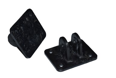
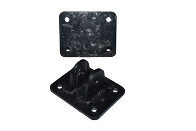
Hybrid manufacturing technique. 9T Labs has developed a hybrid manufacturing technique using its Additive Fusion Technology (AFT), positioning continuous fiber preforms in high-stress regions of a part and discontinuous fiber where there is less reliance on continuous fiber’s strength characteristics. Photo Credit, all images: 9T Labs
Carbon fiber-reinforced thermoplastics (CFRTP) offer an exceptional strength-to-weight ratio, which makes them attractive for structural applications in many industries. However, fiber length is critical to leverage the strength characteristics of the carbon fibers, and manufacturing complexity increases with preserved fiber length.
Continuous fibers provide exceptional mechanical properties. Designers can also optimize them for the load orientation and conditions the part will see in service. Meanwhile, discontinuous fibers provide manufacturing flexibility but with a penalty in strength and load optimization as the material is essentially homogenous.


Techniques like compression molding of long, discontinuous fibers in the form of platelets or bulk molding compounds (BMC) provide an intermediate solution between continuous and short fiber systems for manufacturing relatively complex shapes. However, the high variation in fiber length and performance with these techniques limits part reproducibility.
To take advantage of the benefits of continuous and discontinuous fiber, a hybrid solution is required to position the continuous fiber where it’s needed and discontinuous fiber where there is less reliance on the continuous fiber’s strength characteristics. 9T Labs (Zurich, Switzerland), a firm specializing in additive manufacturing (AM) technologies, alongside Purdue University (West Lafayette, Ind., U.S.), recently developed such a hybrid manufacturing technique using Additive Fusion Technology (AFT).
“AFT is an integrated composites manufacturing software and hardware solution that allows automated manufacturing of complex structural composite parts at scale,” explains Yannick Willemin, director of business development at 9T Labs. “AFT enables the complex manufacturing of thermoplastic composite parts, including additive manufacturing of continuous fiber preforms and their overmolding using discontinuous fiber-reinforced thermoplastic platelet systems. It features cost-competitive structures and sustainable aspects of composites manufacturing to help drive innovation that parts manufacturers can successfully implement into service.”

Pin bracket parts. Unidirectional (UD) carbon fiber-reinforced polymer preforms support the ears and the base of the pin bracket as highlighted, while long, discontinuous carbon fiber-reinforced polymer is used to support the preforms in the mold so the part behaves as an integrated whole.
Recently, Purdue University and 9T Labs used AFT to manufacture a pin bracket for an aircraft overhead bin. Continuous fiber preforms were 3D printed from carbon fiber-reinforced polyetherketoneketone (PEKK) at 60% fiber volume for the high load case regions of the bracket and fiber platelets with discontinuous carbon fiber-reinforced PEKK at 60% fiber volume was applied everywhere else. 9T Labs designed the continuous fiber AM preforms considering the concurrent flow of continuous and discontinuous fibers during compression molding to achieve the desired mesostructure for the final part.
“We started this project with the goal of being efficient in terms of how to use the material and where,” says Eduardo Barocio, assistant director of the Additive Manufacturing Composites Manufacturing and Simulation Center at Purdue University. “This mixed material solution approach using AM preforms and embedding them within compression molded composite structures is something that has never been done before at the granular scale that was accomplished in this project. AM has solved many interesting problems but limitations still exist today. Combining it with a more established and well-characterized manufacturing technique like compression molding has huge advantages, elevating the resulting parts to new levels.”
Hybrid system design
Pin bracket CAD. Pin bracket geometry used to demonstrate compression molding of hybrid continuous and discontinuous fibers.
Initially, 9T labs developed a simulation model of the bracket to specify the operating parameters for it, including the bracket geometry and the functional requirements that provided the study’s design envelope. The load case informed a topology optimization study to determine the position and specification of the AM continuous fiber-reinforced PEKK preforms.
The preforms were to be additively made using unidirectional (UD) tape fed via an overhead gantry-type AM machine onto a build plate. “The preform layup was simulated and optimized to a cost model, ensuring the project resulted in a product that made sense to take to market when it was complete, not just an expensive prototyping task,” says Barocio.

Dimensional drawings. (A) Top and side views of the overhead bin pin bracket and (b) continuous AM composite preforms.
“The continuous fibers within the part are held in place by the thermoplastic matrix (prepreg), which surrounds and supports them, ensuring that the fibers remain in the correct orientation and position, resulting in a strong and durable composite part,” he continues. “We established PEKK as the thermoplastic of choice due to its performance in previous studies. 9T Labs had already used it previously in tape form to produce a helicopter bracket [read “Optimizing a thermoplastic composite helicopter door hinge] that made use of carbon fiber-reinforced PEKK, which were pre-slit to the equivalent of 1-2K tows.”
Non-dimensional parts. Hybrid approach to combine multiple fiber architectures into a single molded part.
9T Labs designed two additively manufactured continuous fiber preforms for the pin bracket — one to reinforce the base and one to reinforce the two vertical flanges or “ears.” Using 9T Labs’ Fibrify Design Suite (FDS), the team determined the fiber layups and generated the code for the preforms. The design suite specified the required amount of continuous fiber slit tape and short fiber filament with the same PEKK matrix material, and the code created instructions for the Build Module.
Idealized reshaping. Idealized continuous fiber preform reshaping by compression molding process.
“The Build Module is an open-material, high-temperature industrial AM machine which manufactures parts using UD prepreg tape and layer-upon-layer material placement using a gantry-based head inside a heated chamber,” explains Willemin. “The use of 1-millimeter-wide slit UD prepreg thermoplastic tape and omnidirectional steering is unique to the Build Module, and the heated material deposition ensures continuous and consistent operation. These characteristics are also ensured during the following fusion process. The deposition system’s infinite rotation allows continuous fiber strands to be located along desired trajectories. The intentional rotation of the base ensures better fiber control and increased print quality in corner regions by deliberate friction.”
9T Labs designed the preforms that reinforce the ears to conform to their contour and support the intersection between the ears and the bracket base using concurrent flow between the continuous and discontinuous fibers. The design of the base preform enables the load to flow partially into the ears, providing a 3D continuous fiber path that connects the mounting face at the base with that in the ears.
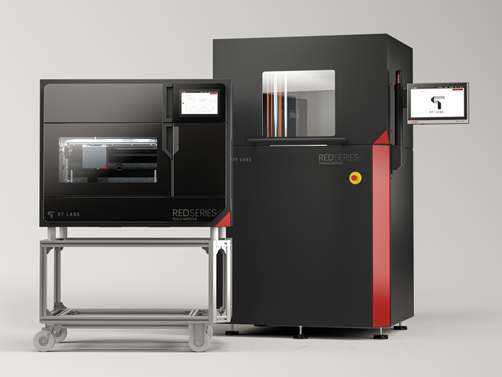
Build Module and Fusion Module. The 9T Labs Red Series Build and Fusion Modules used to produce hybrid CF/PEKK pin brackets.
Each preform is made using 12 plies of 1-millimeter-wide slit UD carbon fiber-reinforced PEKK thermoplastic tape and constructed on a single plane build orientation with 0.2-millimeter layers. This single, continuous fiber spiral loop per ply maximizes strength and minimizes manufacturing time.
The nozzle temperature is 390°C with a bed temperature of 180°C, with rapid build time and multiple batches manufactured on a single 350 × 270-millimeter removable build plate. The fiber tool path for each preform results in three contours with a final wall thickness of 3 millimeters. The base preform contains 12 meters of 1-millimeter-wide tape, requires no post-processing and is ready to be placed directly into the mold. The ear preform contains 8 meters of 1-millimeter-wide tape cut post-process at a predefined location. The continuous fiber preforms make up 17% of total part volume.
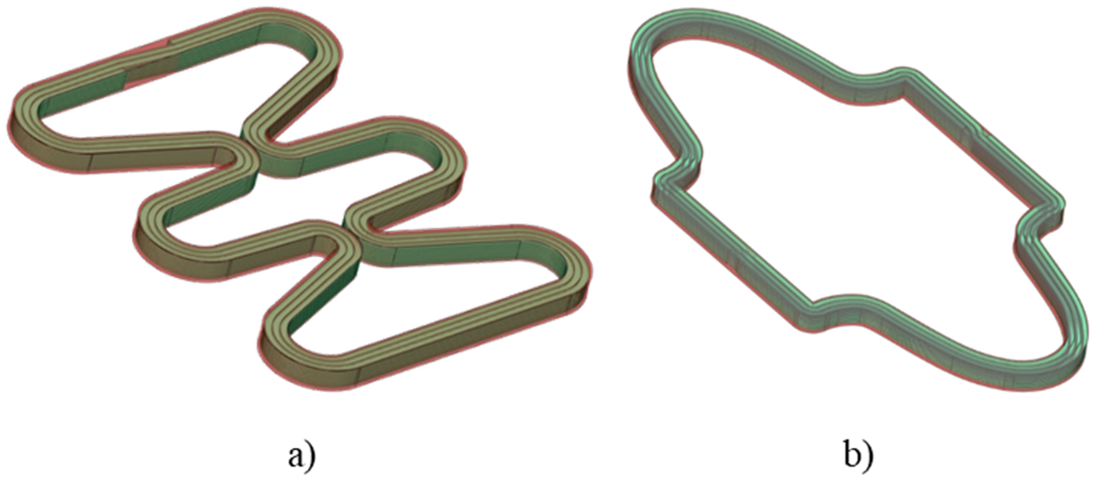
Engineered preforms. Engineered continuous fiber preforms for the flange (a) and ears (b).
AM-reinforced compression molding
Post-AM, the preform parts are delivered to the Fusion Module. The Fusion Module is a compression molding machine that consolidates the preforms and reshapes them as desired for consolidation in the final part.
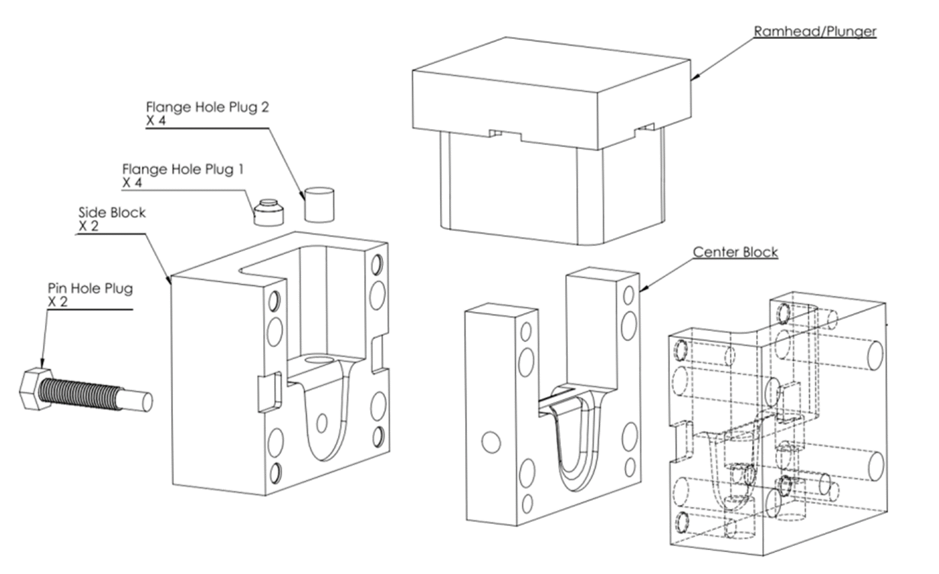
Molding tool. Compression molding tool used to fabricate pin bracket.
“Compression molding is complex, involving multiple anisotropic phenomena including flow characteristics, thermoelastic and crystallization shrinkage, viscoelasticity, heat transfer, as well as polymer crystallization and melting kinetics,” explains Barocio. “The addition of continuous fiber-reinforced preforms provides an opportunity to manufacture structurally optimized compression molded parts with complex geometries. However, achieving the required mechanical properties presents challenges depending on the material, machine and process parameters. The initial orientation of the preforms, the discontinuous fiber platelets and the anisotropic flow during manufacturing facilitates the final part’s structure.”
The compression molding tool is made from H13 steel and features inserts to mold the hole for the pin and the holes at the bracket’s base. A thermocouple well records temperature during manufacturing. The fabrication of the pin bracket begins with the installation of the preforms that reinforce the pin bracket ears into the compression molded tool. Next, three tool blocks are installed, and the base preform is placed in the tool cavity.
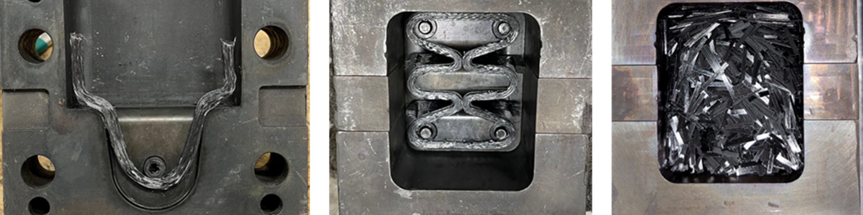
Manufacturing of pin bracket. Manufacturing of pin bracket steps including (left to right) placement of the continuous fiber preform for ear reinforcement (a), placement of preform at the base of the pin bracket (b) and tool cavity filled with platelets after installing preforms (c).
Pins are used to position the mounting holes at the base of the pin bracket and serve to constrain the movement of the continuous fiber preforms during manufacturing. The preforms are reshaped around the pins pre-molding to isolate their position in the final part. Such reshaping of the preforms improves the load-carrying capabilities by aligning the continuous fibers with the applied load transmitted by the pin into the bracket.
“The pins in the flange serve to anchor the continuous fiber perform as the compression molding process develops, thereby producing a continuous fiber path for load transfer between the base and the ears,” highlights Barocio. “Although we additively manufactured the continuous fiber preforms on a single plane, we achieve 3D load-carrying capacity within the pin bracket by placing them in different planes in the mold and through reshaping driven by the flow of preform material into the mold. That means the part takes maximum advantage of the preforms with the least amount of waste possible, as they are accurately located where required in the structure.”
Carbon fiber-reinforced PEKK was used for the platelet-reinforced polymer element, removing the requirement to work on the material parameters to accommodate compatibility for complete consolidation. Following the preparation of the compression molding charge, the tool’s plunger is installed, and the tool assembly heats to a processing temperature of 390°C in a forced convection oven.
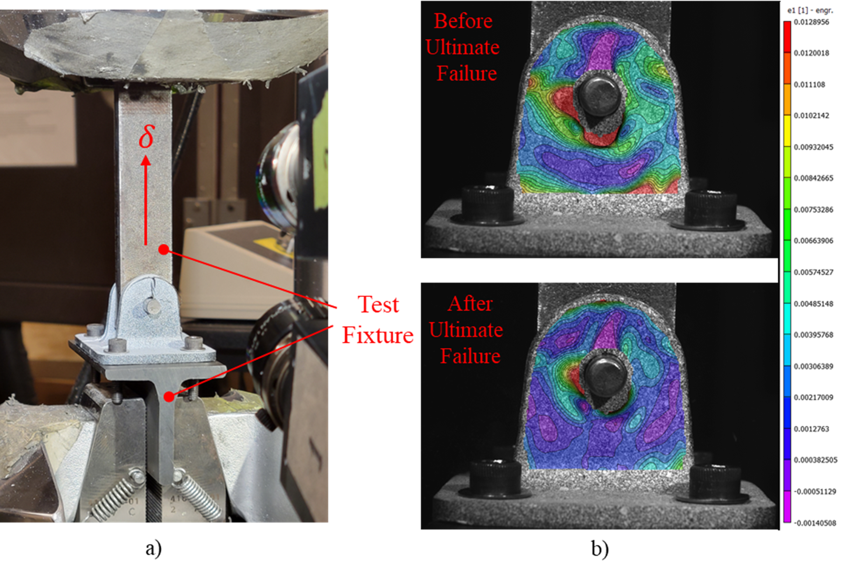
Setup and strain. Setup for mechanical testing of pin brackets (a) and strain field in the load direction before and after ultimate failure in a pin bracket reinforced with continuous fibers (b).
Upon reaching the processing temperature, the tool assembly transfers to a hot press to flow and consolidate the molding charge into the tool cavity. A pressure of 124 bar is applied while the tool cools down to below the polymer’s glass transition temperature. The hot press platens are pre-heated to 220°C to reduce the cooling rate and allow the development of crystallinity in the polymer. Demolding takes place at 150°C.
“The continuous carbon fiber-reinforced PEKK pin bracket was designed to the structural performance of the part but also by the flow conditions developed in the compression molding process,” notes Barocio. “When we move into the consolidation phase, it brings together the preforms' final shape and performance properties as it will behave in the final product.”
Pin bracket enhancements
The final AM pin bracket weighs 31.5 grams — the preforms represent 17% (5.4 grams) of the overall weight, with the remaining 83% (26.6 grams) of total part volume as short discontinuous compression molded fiber platelets. 9T Labs fabricated six carbon fiber-reinforced PEKK pin brackets with continuous fiber preforms and platelets, and pin brackets fabricated with only platelets for comparative testing. An MTS 810 equipped with a 100-kilonewton load cell was used to perform quasi-static tests. A custom-made fixture loaded the pin bracket in tension with four 10-32 screws torqued to 40.67 newton-meters. A displacement control procedure was carried out at a rate of 2 millimeters/minute until the bracket reached ultimate failure. Digital image correlation (DIC) was used to record the strain field developed at the surface of the pin bracket’s ears during loading.
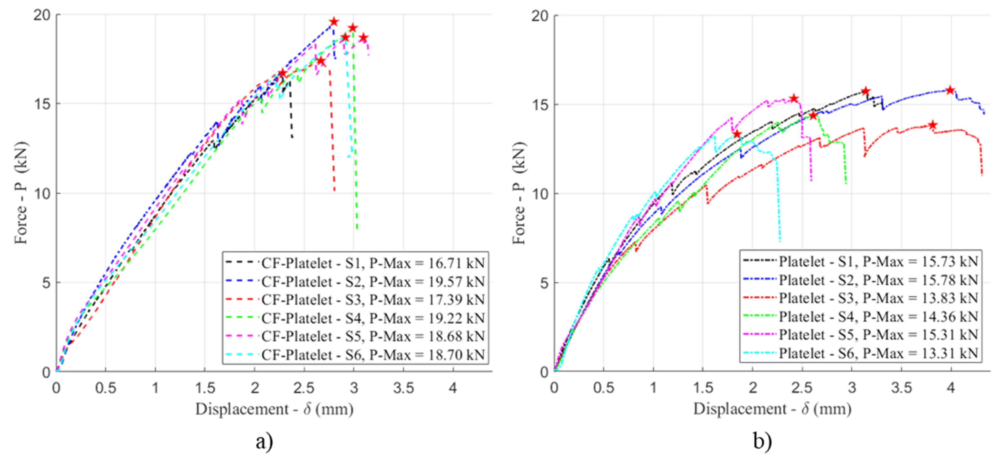
Load displacement curves. Load-displacement curves show the pin bracket fabricated with continuous fiber preforms and platelets (a) compared to pin brackets fabricated with platelets only (b).
The company observed that the linear elastic region is more significant in the brackets molded with the AM preform reinforcement (hybrid) material system. The hybrid material demonstrated a load at the onset of damage of 15.67 kilonewtons, a 99.6% increase over the platelet-only material, which achieved 7.67 kilonewtons. The maximum load applied to a bracket before a monotonic decrease in the load-carrying capacity also increased by 25% from 14.72 kilonewtons for the platelet-only material, to 18.38 kilonewtons for the brackets constructed with the hybrid material.
The coefficient of variance of the load at the onset of failure decreased by 46% from 18.19% to 9.81% with the hybrid material. At ultimate failure, the coefficient of variance of the load was 14.8% better in the hybrid material, 7.05% over 6.01% for the platelet-only version.
“It’s clear that the hybrid composite demonstrated significant enhancements to the mechanical performance of the pin bracket solely made from a platelet material,” highlights Barocio. “The continuous fiber preforms improve load transfer between the ears and the base of the pin bracket geometry, as well as the the flow and shape/position of the fibers, taking them from a planar configuration into a 3D fiber architecture.”
“The reshaping of the continuous fibers — driven by the concurrent flow of the continuous and discontinuous fiber systems in the compression molding process — performed as desired, reinforcing the pin bracket’s strength characteristics but also decreasing its variability,” he continues. “These enhancements result in positive implications to the allowable design and implementation of this class of materials.”
Pin bracket perspective. The hybrid material version of the pin bracket outperformed the platelet-only version in every aspect including a load at the onset of damage improvement of 99.6%, a load-carrying capacity increase of 25% and coefficient of variance of the load at the onset of failure, which decreased by 46%.
The hybrid material and process technology produced by 9T Labs and Purdue in this project offers significant potential to optimize the use of fiber-reinforced thermoplastics in structural components with complex geometry. However, Barocio says, “There is a need for physics-based process simulations that include phenomena such as the concurrent flow of continuous and discontinuous fibers. Similarly, further understanding and optimizing the interfaces between the continuous and discontinuous fiber systems will benefit this technology. Finally, a predictive simulation framework is paramount to enable designing simultaneously for manufacturing and performance, thus unleashing the full potential of this technology.”


Related Content

The state of recycled carbon fiber
As the need for carbon fiber rises, can recycling fill the gap?
Read More
Infinite Composites: Type V tanks for space, hydrogen, automotive and more
After a decade of proving its linerless, weight-saving composite tanks with NASA and more than 30 aerospace companies, this CryoSphere pioneer is scaling for growth in commercial space and sustainable transportation on Earth.
Read More
Price, performance, protection: EV battery enclosures, Part 1
Composite technologies are growing in use as suppliers continue efforts to meet more demanding requirements for EV battery enclosures.
Read More
One-piece, one-shot, 17-meter wing spar for high-rate aircraft manufacture
GKN Aerospace has spent the last five years developing materials strategies and resin transfer molding (RTM) for an aircraft trailing edge wing spar for the Airbus Wing of Tomorrow program.
Read MoreRead Next

Metal AM advances in composite tooling, Part 1
Multiple metal additive technologies are gaining market acceptance and interest for composite tooling used in processes ranging from short-fiber injection to autoclave-cure prepreg.
Read More
High-performance, high-detail continuous 3D-printed carbon fiber parts
Since 2014, Mantis Composites has built its customer and R&D capabilities specifically toward design, printing and postprocessing of highly engineered aerospace and defense parts.
Read More
3D printing with continuous fiber: A landscape
Growth continues in suppliers, part size, production volume and markets.
Read More