


A study conducted jointly by ORNL and IACMI attempted to 3D print developmental tooling to compression mold sheet molding compound (SMC) using high-temperature carbon fiber-reinforced thermoplastics (CFRTP) on a large-format additive manufacturing (LFAM) system at ORNL. While more work is needed, the research showed that the concept is feasible. In time, this could offer manufacturers a third option between relying solely on simulations or spending significant time and money to produce hard tooling when developing new composite parts. Photo Credit, all images: Oak Ridge National Laboratory (ORNL), U.S. Department of Energy (DOE).
OEMs and members of the composites supply chain are constantly challenged to find new ways to bring parts to market faster at less cost without sacrificing critical properties. As simulation tools become more accurate, and materials and molding processes get faster, the high cost and long lead times needed to produce metal molds for forming parts has ultimately become the rate-limiting step. Hence, much interest is focused on exploring additive manufacturing (AM) technologies — polymer and metal 3D printing — to produce viable tooling to debottleneck this critical step.
Versus traditional “subtractive” manufacturing methods (e.g., grinding, cutting, drilling and electrical discharge machining (EDM)), which can require up to 24 weeks to produce large automotive tools in P20 steel for compression or injection molding, AM offers the possibility to reduce tool production time from months to weeks — or even days — while also reducing cost and weight (the latter helping reduce the total carbon footprint of tool production).


This story reports preliminary research on 3D printing of thermoplastic composite tooling for compression molding sheet molding compound (SMC) at the U.S. Department of Energy’s (DOE’s) Manufacturing Demonstration Facility (MDF) at Oak Ridge National Laboratory (ORNL) in Knoxville, Tenn., U.S., as part of a larger research program under the auspices of the Institute for Advanced Composites Manufacturing Innovation (IACMI, Knoxville), a DOE Manufacturing USA Institute.
Project scope
This project began as part of a larger, multi-year IACMI program involving a European automaker and other IACMI member organizations representing the automotive composites supply chain.
“Our OEM partner on this project wanted to learn all about SMC, so we designed a series of experiments to explore what was possible while keeping an open mind,” recalls Uday Vaidya, University of Tennessee-Knoxville/ORNL governor’s chair in advanced composites manufacturing and IACMI chief technology officer (CTO). “One of the things we looked at was whether we could 3D print composite tooling to mold SMC.”
“From the start, we knew we wouldn’t be producing tools durable enough for commercial manufacturing,” adds Ahmed Arabi Hassen, ORNL R&D staff scientist – composites innovation group, Manufacturing Science Div. “However, the prospect of producing prototype molds quickly and inexpensively was an intriguing opportunity we wanted to explore since it would provide manufacturers with an alternative to relying solely on simulations or paying to produce costly and time-consuming hard tooling.”
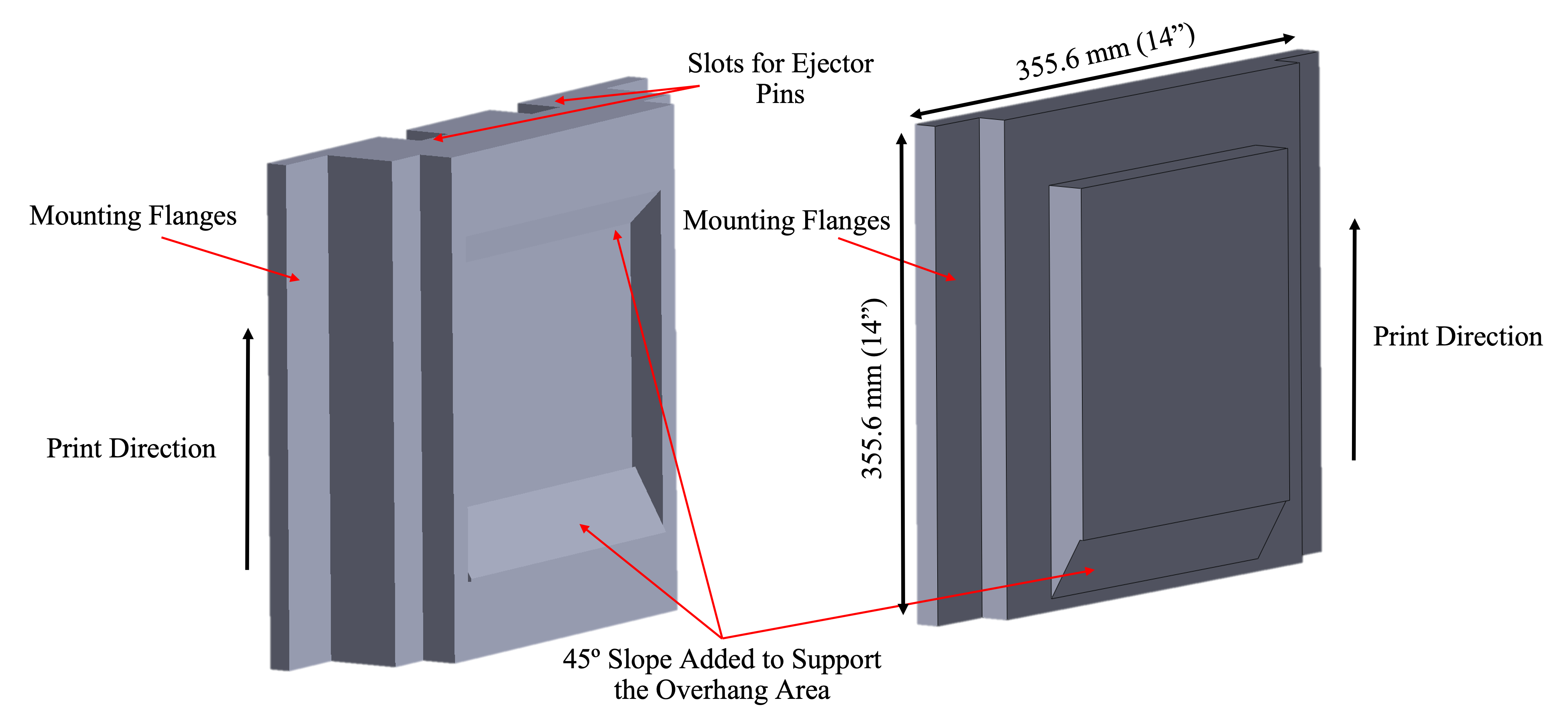
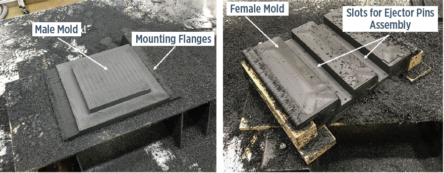
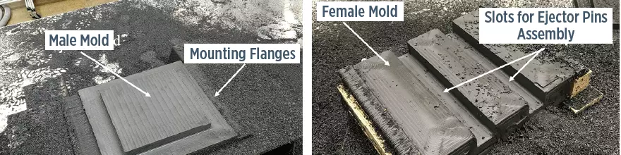
Core and cavity designs for plaque tool printed in CF/PPS on the BAAM (top) and photos of both tool halves after post-print machining (bottom), including the slots to house an experimental pneumatic ejector pin system.
Researchers began by defining the performance requirements for compression tooling to mold SMC, which included withstanding molding temperatures of 130-150°C and molding pressures up to 13.8 MPa.
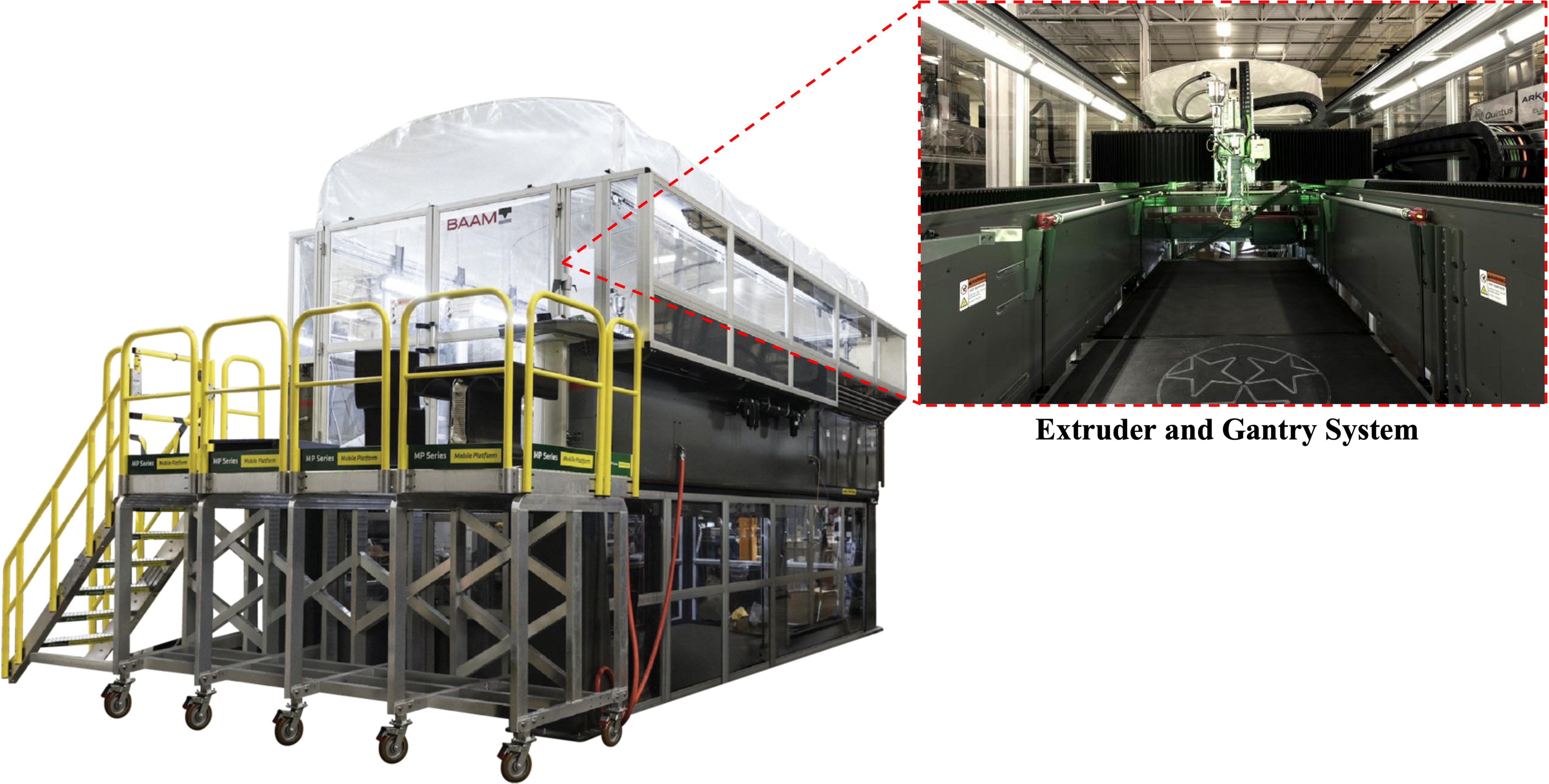
ORNL’s team had previously investigated polymer and metal AM tooling ranging from trim molds to high-pressure/high-temperature autoclave molds. This project represented ORNL’s first attempt to produce polymer AM tools to compression mold SMC and may well represent the first such work globally. Work was done at ORNL’s MDF using a Big Area Additive Manufacturing (BAAM) printer co-developed by Cincinnati Inc. (Harrison, Ohio, U.S.) and ORNL. This extrusion (fused filament fabrication (FFF) type) printer is fitted with large nozzles (10.16 millimeters in diameter) that can deposit at a rate of 45 kilograms/hour and produce parts 6 meters long x 2.5 meters wide x 1.8 meters tall using polymer feedstocks in pellet form. BAAM’s tradeoff of being able to print big parts fast is that print resolution is low and produces a bumpy surface that requires post-print machining. Hence, toolpaths are printed slightly oversized to achieve correct dimensions after post-print cleanup.
“Because we’d previously explored all the low-hanging fruit, like 3D printing layup and autoclave tools, we’d already screened a broad range of thermoplastics that could be printed on the BAAM,” continues Hassen. “We’d identified three high-temperature, carbon fiber [CF]-reinforced materials that had the thermal and mechanical performance to mold SMC.” These included two amorphous thermoplastics — polyphenylene sulfone (CF/PPSU) and polyethersulfone (CF/PES or CF/PESU) — and one semi-crystalline, polyphenylene sulfide (CF/PPS). Given the large size of parts typically printed on the BAAM, researchers chose polymers reinforced with carbon rather than glass fibers to keep tools stiff and strong yet lightweight. The MDF team had previously identified the practical range of CF reinforcements for each polymer family. For example, semi-crystalline PPS achieved higher fiber weight fractions (FWF) of 40-60%, with 50% considered the sweet spot. “Below 50%, we found performance could still be improved, but above 60% we found dry fiber bundles,” Hassen adds.
Since PES and PPSU are amorphous, their viscosity is higher at wetout/molding temperatures, making it harder to achieve high fiber loadings. FWFs between 20% and 35% were achievable, with 25% considered the sweet spot. “Although we could achieve higher fiber loadings and therefore higher mechanical performance with PPS, that material was more prone to warpage and cracking when printing some shapes since we cycled tool temperatures and pressures up and down,” Hassen notes. That feature would limit material options as the study proceeded.
Proof of concept: Plaque
Researchers began by printing a square plaque mold in CF/PPS with final exterior dimensions of 355.6 x 355.6 x 3.2 millimeters. The project’s goals were for the tool to survive 1.03 MPa molding pressures and 130-150°C molding temperatures. To ensure printability, they modified overhang (90°) angles in the mold and printed the longest side vertically (in the Z-axis). Additionally, to prevent hot thermoplastic from slumping in overhang areas as it cooled, they added removeable 45° chamfered supports, which were subsequently machined away after printing. Core and cavity sides of the tool were printed side by side in the BAAM. Other features incorporated into the print included slots that were printed on the back side of the female tool to house ejector pins. Given that post-print machining was needed to achieve an acceptably smooth finish on the molding surface, geometry was oversized by half a bead (5.08 millimeters). After printing, the interior mold surface was machined smooth. Additionally, locations to hold four ejector pins were drilled and a pneumatic ejector pin system was installed in the tool.
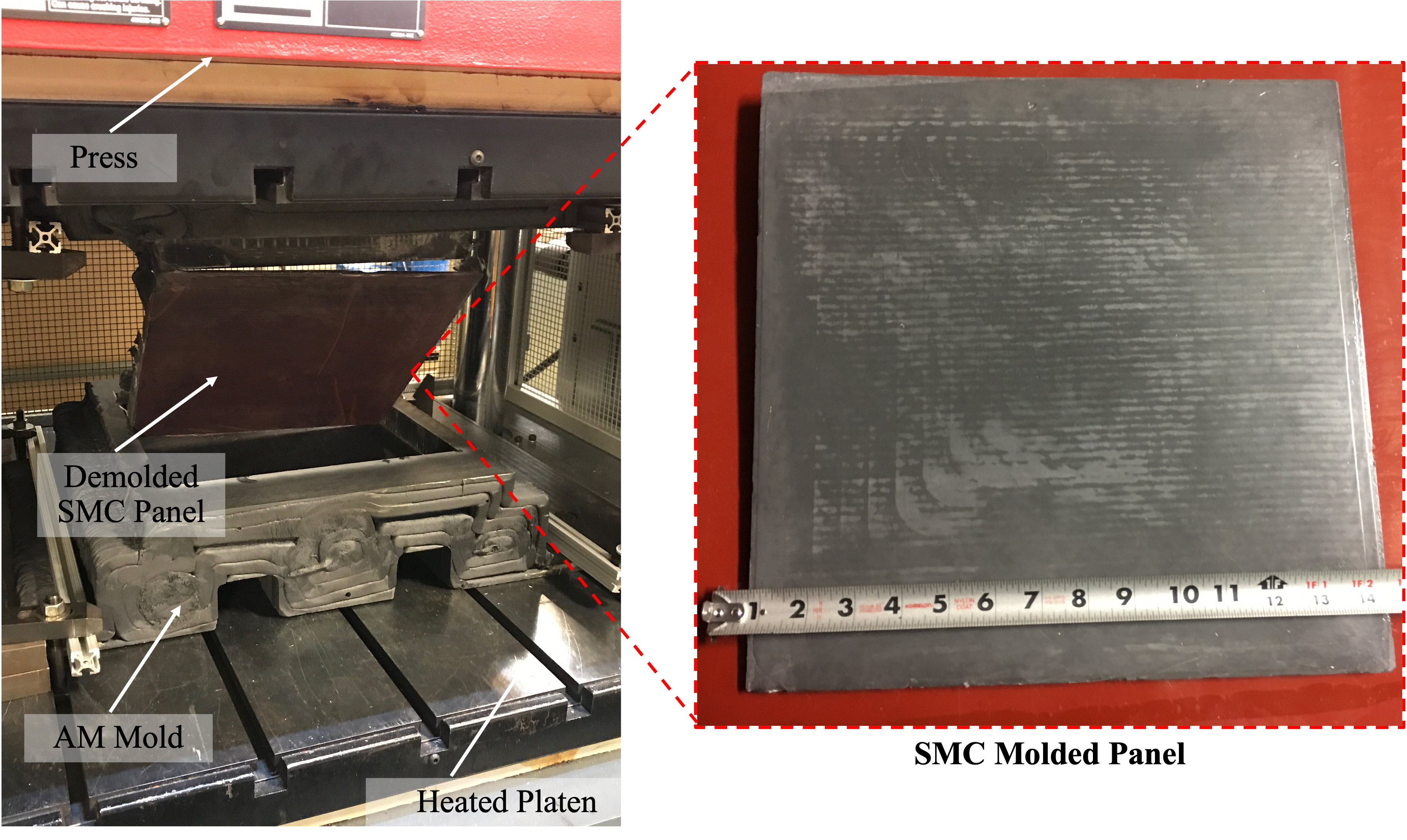
The CF/PPS plaque tool successfully molded SMC plaques. Material released properly, was fully cured and the experimental ejector pin system worked well.
Next, the tool was mounted in a compression press and indirectly/passively heated for 12 hours to 180°C using the press’ platens, which were set at 190°C. Such a long warm-up cycle was necessary because the tool was printed in a thermoplastic with fairly low thermal conductivity, despite the presence of 50% FWF carbon fiber, which itself has excellent thermal conductivity. Researchers monitored molding surface temperatures via embedded sensors. They noted a 15-20°C drop each time the press was opened to remove parts and load new SMC charges. That necessitated removing the part, closing the press and waiting for the tool to reach temperature again before opening the press to load material for the next cycle.
To reduce heat loss and help keep the molding surface from dropping below 150°C, additional insulation was placed around the mold. SMC was laid directly on the composite tool surface. A molding temperature of 150°C and clamping pressures of 10 tonnes were used to form and cure the material, which had a dwell time of five minutes. Twelve parts in total were produced and overall results were positive. The material cured properly and released without issue from the CF/PPS surface, which was occasionally sprayed with mold release. Additionally, the ejector pin system worked well and material did not flow between pin clearances during forming.
Seatback demonstrator
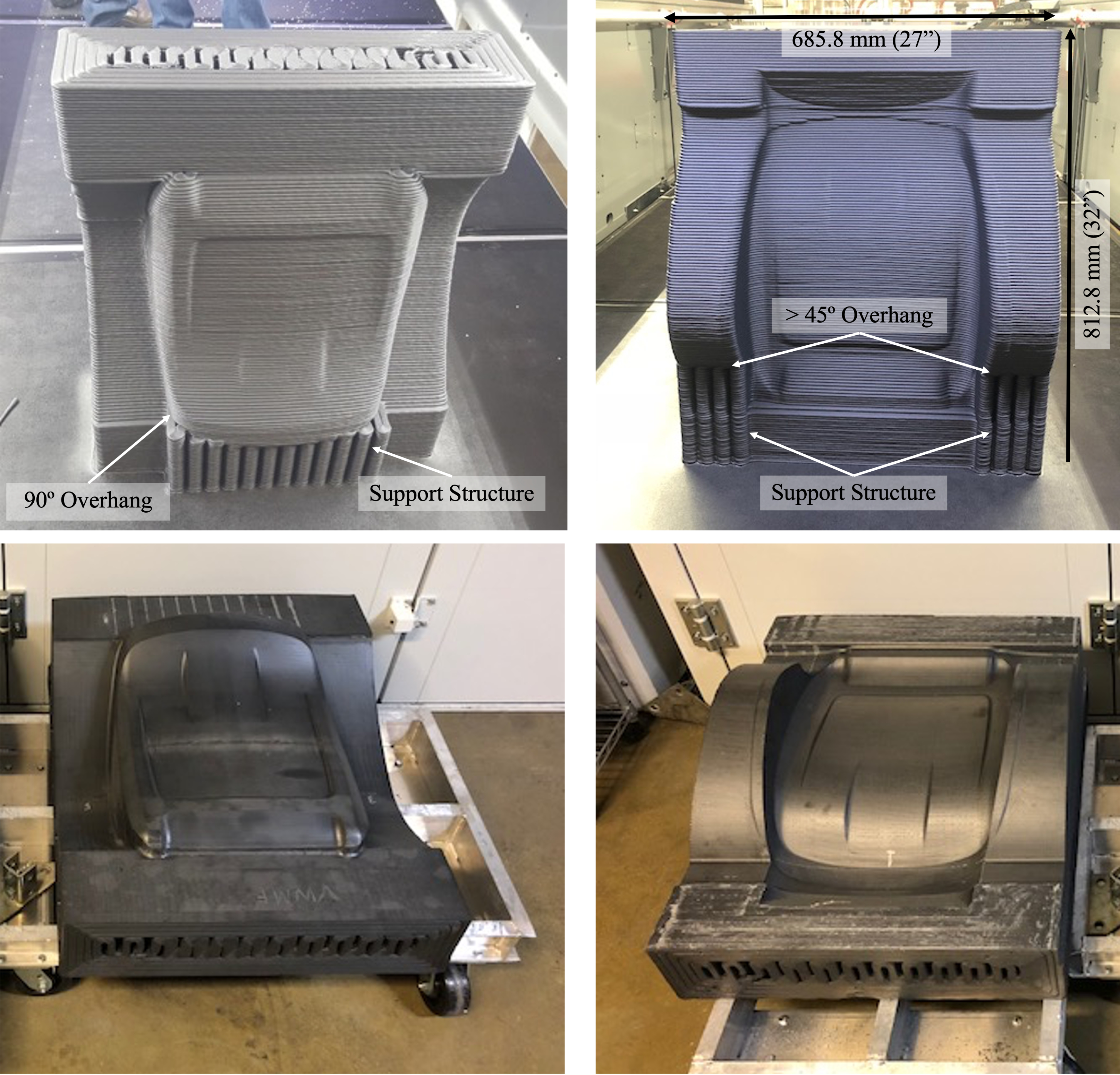
As printed (above) and post-print machined (below) seatback mold halves in CF/PPSU.
Researchers next scaled the technology up to print a larger (812.8 x 685.8 x 304.8 millimeters), more complex automotive seatback mold. Again, geometry was modified for printability and by adding removable support structures for overhang areas. This time, 25% FWF CF/PPSU was used. Core and cavity halves were produced separately, with each half printing within four hours. As before, post-print machining was used to clean up surfaces. This tool was deemed shallow enough to not require ejector pins.
As before, the mold was mounted in the press and heated for 12 hours using the press’ platens, which were again held at 190°C. Since this feedstock had even lower thermal conductivity (due to lower CF loading), the molding surface only reached 105°C, which was too low to cure SMC. As before, insulation was placed around the mold to better retain heat. However, after another 12-hour heating cycle, internal temperatures only reached 120-125°C across the forming surface. To determine if this was sufficient to cure SMC, a charge was loaded into the tool and 30 tonnes of clamping pressure was applied. Researchers observed the mold surface lost 10-15°C each time the tool opened and closed, meaning it couldn’t maintain the required temperature to properly cure SMC. Researchers discussed raising the temperature an additional 10-15°C to offset losses but deemed this impractical owing to the length of time required to heat the tool. Only two parts were successfully molded. One part was properly consolidated and cured, while the other showed sections of poor consolidation and curing.
Issues management and next steps
At this point, researchers reviewed project results and identified outstanding issues.
On the plus side, tools were printed, machined and fitted in a matter of days — at far less time and cost than conventional metal molds despite using much higher cost materials. Additionally, printed tools handled SMC forming temperatures and pressures, and, once machined, molding surfaces were considered smooth enough to produce an acceptable part finish (although not automotive Class A quality).
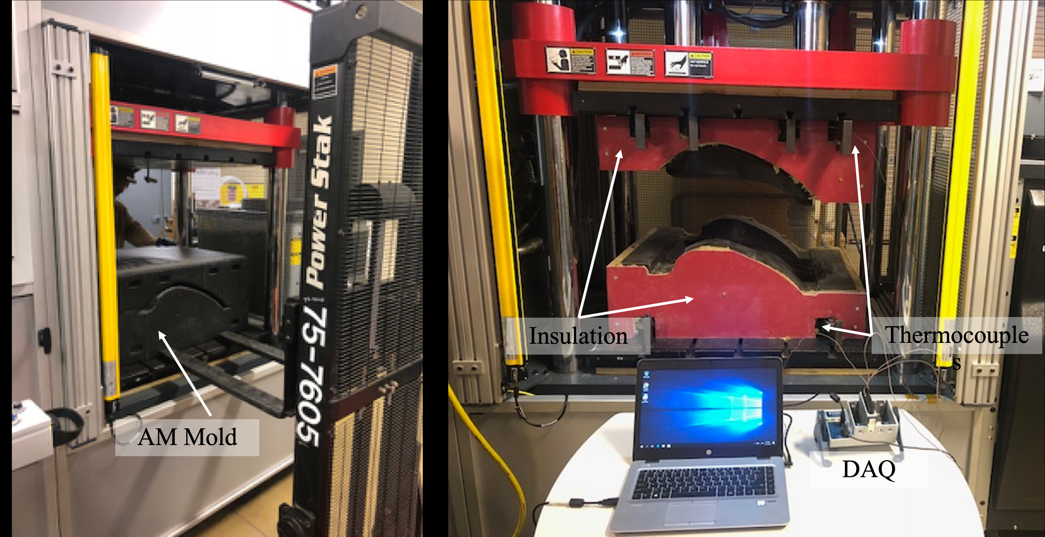
Seatback mold halves mounted in compression press ready to produce parts. As before, the press’ platens were used to passively heat the mold to temperature.
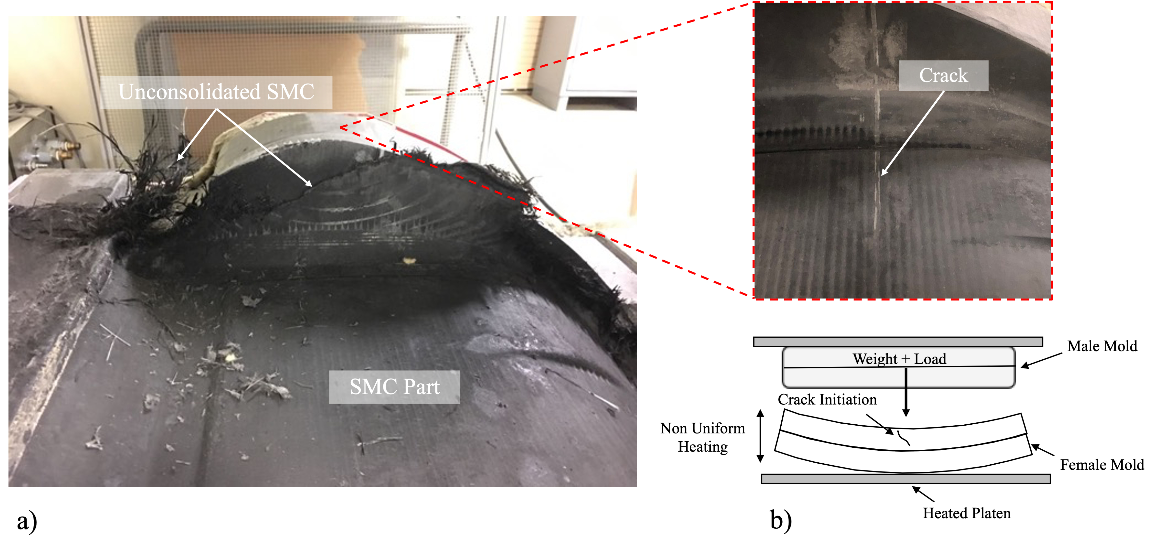
The larger and more complex automotive seatback mold proved difficult to heat and maintain temperature in, which led to non-uniform heating and distortion in the mold and areas of poor consolidation (a) and cracking (b) in the part.
On the other hand, each tool’s low thermal conductivity caused poor and unacceptably slow heat transfer from the press’ heated platens and lost heat quickly each time the press opened. Also, both tools had non-homogeneous structures (a function of print direction and fiber alignment) and non-uniform thermal profiles, which led to warpage and cracking in the PPS tool during extended heating cycles, as well as inconsistent consolidation and curing of thin-section SMC in the PPSU tool.
Researchers concluded that passively heating tools solely by conduction from the press’ platens was inefficient, so they brainstormed ways to heat tools faster. While inductive mold heating was considered, the cost and complexity of retrofitting tools was outside this short-term study’s scope, as was using alternative higher thermal conductivity feedstocks. Hence, the focus shifted to developing more efficient active heating methods. Several options were proposed and evaluated
“Despite identifying a number of technical issues, we needed to address, such as using some form of integrated active heating to reach and hold SMC molding temperatures, we were very pleased that our wild idea of printing compression tools worked,” adds Hassen. “Since this project ended, it’s proven to be the nucleus of a lot more research.”


Related Content

Automated robotic NDT enhances capabilities for composites
Kineco Kaman Composites India uses a bespoke Fill Accubot ultrasonic testing system to boost inspection efficiency and productivity.
Read More
Bladder-assisted compression molding derivative produces complex, autoclave-quality automotive parts
HP Composites’ AirPower technology enables high-rate CFRP roof production with 50% energy savings for the Maserati MC20.
Read More
Revolutionizing space composites: A new era of satellite materials
A new approach for high volumes of small satellite structures uses low-CTE, low-cost CFRP cellular core, robust single-ply skins and modular panel systems to cut lead time, labor and cost for reflectors, solar arrays and more.
Read More
Reinforcing hollow, 3D printed parts with continuous fiber composites
Spanish startup Reinforce3D’s continuous fiber injection process (CFIP) involves injection of fibers and liquid resin into hollow parts made from any material. Potential applications include sporting goods, aerospace and automotive components, and more.
Read MoreRead Next

Collaborative Boeing-led project validates large-scale composite AM tooling
The U.S. Navy-funded program demonstrated a large-scale, autoclave-curable 3D-printed carbon fiber composite tool using a Thermwood LSAM machine.
Read More
How to validate 3D-printed composite part performance
Integrated Computational Materials Engineering (ICME) workflow simulates composite material performance to speed development, optimize performance and reduce costs for a redesigned 3D-printed CFRP bracket.
Read More
Ultrasonic welding for in-space manufacturing of CFRTP
Agile Ultrasonics and NASA trial robotic-compatible carbon fiber-reinforced thermoplastic ultrasonic welding technology for space structures.
Read More