


Photo Credit, all images: Danfoss, Markforged, Hexagon
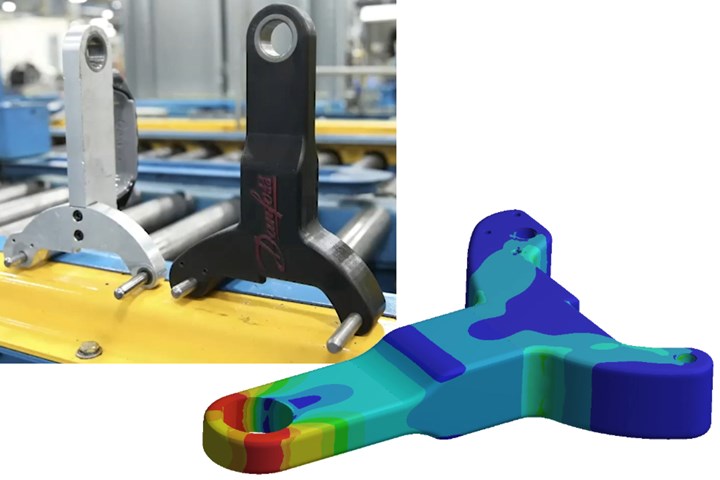
Danfoss Power Solutions (Ames, Iowa, U.S.) wanted to reduce cost and lead time challenges with a machined aluminum bracket by redesigning it to use carbon fiber-reinforced plastic (CFRP) made with its Markforged (Watertown, Mass., U.S.) 3D printer. The bracket is used to lift heavy cast metal components during CNC machining and assembly (Fig. 1).
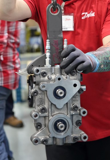
Fig.1. 3D-printed composite lift fixture
Danfoss worked with Markforged and Hexagon to predict the performance of this lift bracket, redesigned from machined aluminum to 3D-printed composite.
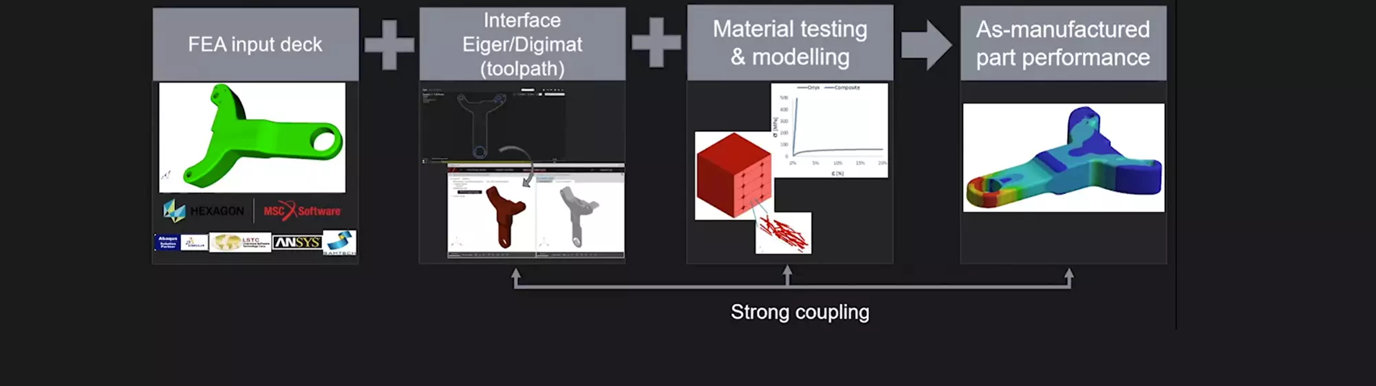
In 2019, Markforged and MSC Software Corp. (MSC, Irvine, Calif., U.S.) announced a partnership to connect Markforged material and print information with MSC finite element analysis (FEA) simulation, enabling simulations of fiber-reinforced 3D-printed parts to predict mechanical and structural performance. A simulation workflow was developed, comprising Markforged’s Eiger design software and Digimat material and process modeling software from e-Xstream engineering (Käerjeng, Luxembourg), a division of MSC. Both are now part of Hexagon Manufacturing Intelligence (Cobham, U.K.), which traditionally dealt with metrology and inspection after production, but now has capability to feed that information back into design and manufacturing optimization. This 3D-printed composite simulation workflow was validated on the Danfoss bracket, and potential for failure was investigated.


Integrated Computational Materials Engineering (ICME)
ICME is an approach that Hexagon has industrialized to simulate composite part performance. For example, Digimat is used to perform injection molding simulations, deduce the fiber orientation throughout the part and run a coupled FEA simulation using the as-manufactured material microstructure to derive the actual mechanical behavior in the part. Through the partnership with Markforged, ICME has now been adapted for 3D-printed composites. Key steps include:
- Define the part’s toolpaths/fiber paths in Eiger and build an FEA model in Abaqus, Ansys, etc.
- Export toolpath data from Eiger into Digimat
- Perform material testing and modeling to calibrate the Digimat material model
- Run FEA to evaluate as-manufactured part performance.
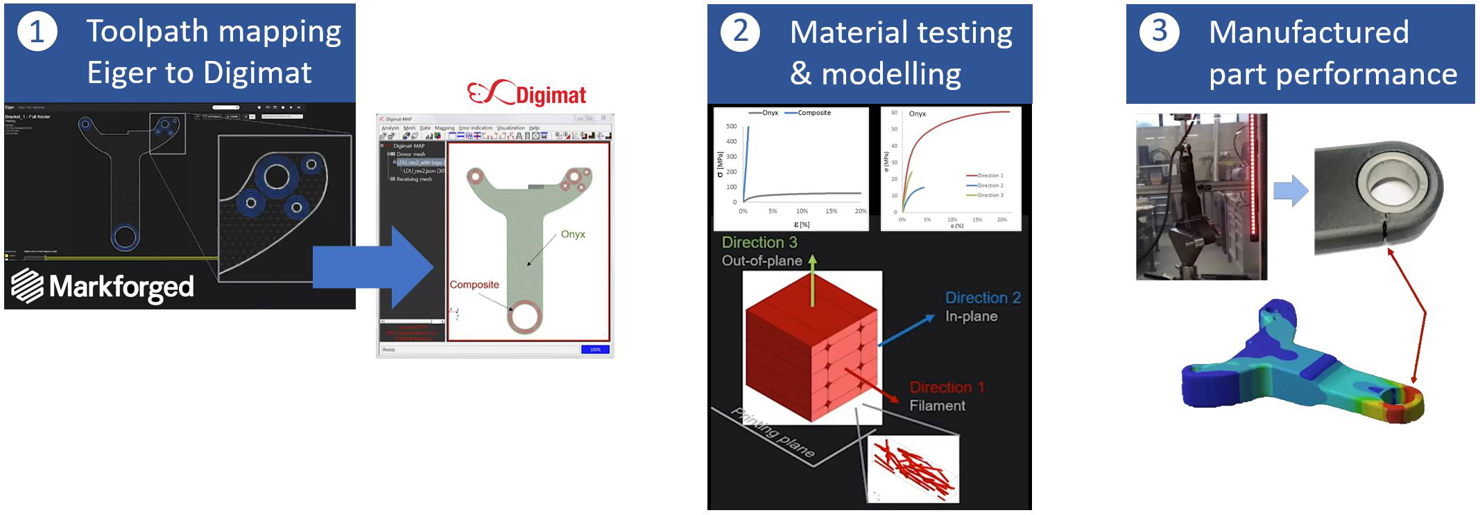
Fig. 2. Validated failure prediction
The final three steps in ICME are shown here, ending with an FEA simulation that predicted maximum strain at the top lifting ring, validated by physical testing and addressed by adding continuous carbon fiber. Photo Credit: Danfoss, Markforged, Hexagon
Eiger software
The composite bracket was designed to roughly maintain the shape of the previous aluminum part, but converted the multi-part assembly into a single printed piece that was lighter weight thanks to fiber paths tailored to align with in-service loads. After importing the CAD file into Eiger, two designs were created. One used only Markforged’s Onyx short fiber-reinforced polyamide 6 (PA6) filament. A second design added five layers of continuous carbon fiber, for example, to reinforce the outer planes of the part, the lifting ring at top and twin pin openings at bottom. In both designs, an infill pattern printed with Onyx filament was used where possible to reduce printed material and weight. Eiger can also design areas of isotropic properties and tailor section modulus to meet deflection requirements.
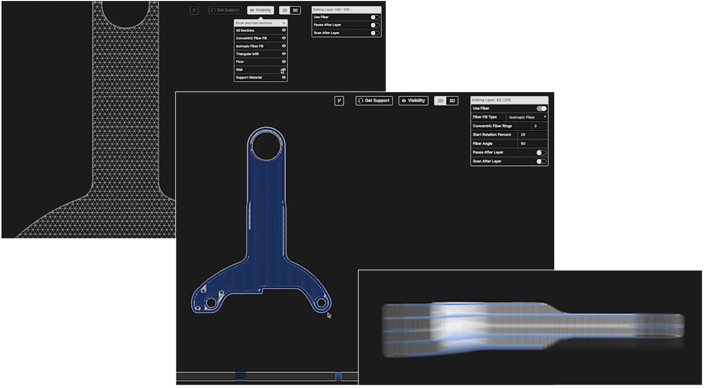
Screenshots from Markforged’s Eiger software show (from left to right) infill pattern using Onyx filament, concentric continuous carbon fiber around the bracket’s top lifting ring and twin pin openings at bottom and a side view showing five layers of continuous carbon fiber in the second design.
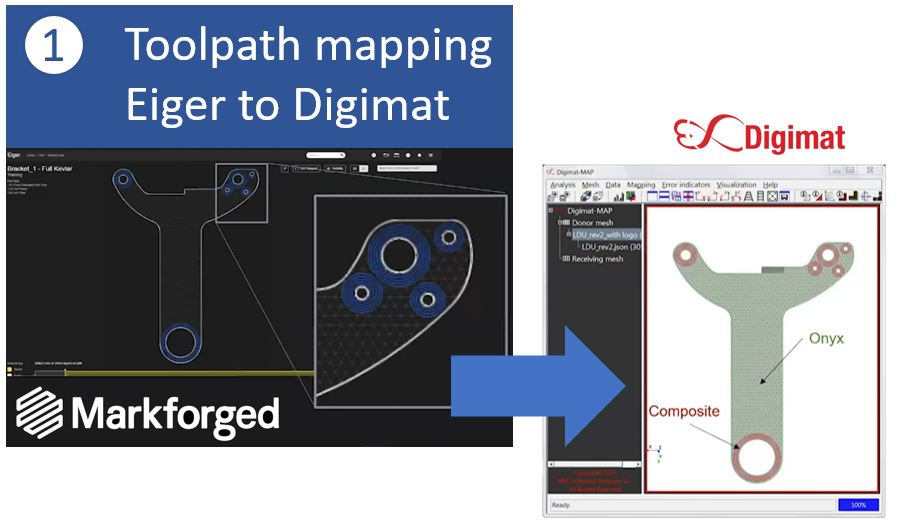
Map print toolpaths to FEA
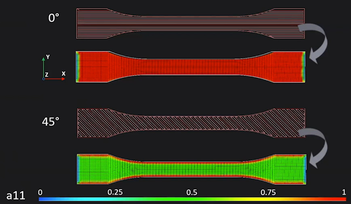
This illustrates how fiber orientation is mapped from Eiger to Digimat in a tensile test specimen. Fiber orientation for each layer is valued between 1 (aligned, red) and 0 (orthogonal, blue), with 45° shown as green. For both the 0° and 45° layers, there is some blue at the ends where orthogonal fiber has been placed.
An FEA model was created with in-service loads and boundary conditions using Ansys, Abaqus, or other standard FEA software. The next step was to export the 3D print toolpath data from Eiger to Digimat using the proprietary interface developed by Markforged and Hexagon. This step maps the filament material data (Onyx and continuous carbon fiber) along with fiber orientation from the 3D print toolpath onto the FEA structural mesh. A Markforged webinar on this case history gives more detail on how this mapping is achieved. Note in the second image for step one of Fig. 2 that fiber orientation for each layer in the part can be valued between 1=fiber aligned with the principal direction and 0=fiber orthogonal to this direction.
Calibrate Digimat material model
At this point, mechanical testing was performed on 3D-printed tensile coupons for Onyx and continuous fiber composites to calibrate the Digimat material model. This ensures the model accurately reflects the mechanical properties achieved in the characteristic directions (x,y, z) defined by the 3D printing toolpath in each printed plane, which enables the FEA model to reflect the as-manufactured part.
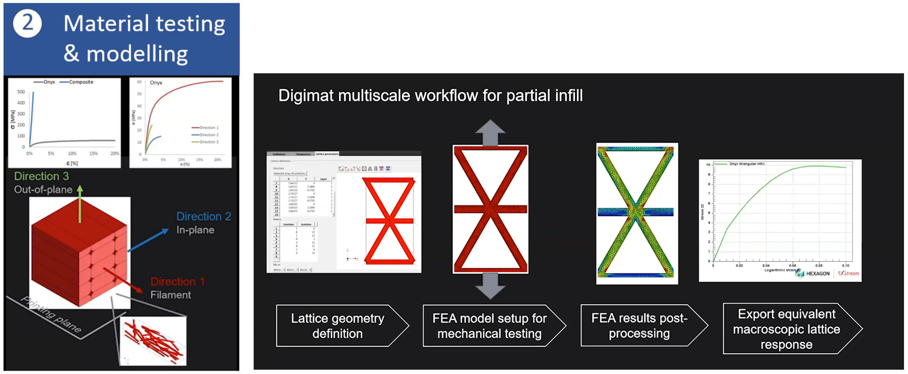
The Onyx infill in the printed lift bracket also needed to be accurately represented. To do this, a separate FEA was created and solved using Digimat FE, a tool within the Digimat platform. “We created a representative unit cell of the triangular infill geometry and then used Digimat FE to help automate assigning material behavior, boundary conditions and loads,” says Olivier Lietaer, business development engineer AM (additive manufacturing) at Hexagon. “We then ran the analysis on the infill model and, after post-processing the different results, we exported an equivalent macroscopic response for the lattice to the lift bracket FEA model. In this way, you don’t have to mesh the infill very finely in the model of the as-printed part. Thus, we have enabled a multi-scale workflow that takes into consideration the as-printed microstructure at the structural analysis FEA level that mechanical engineers need.”
Validate part performance
Finally, the coupled Digimat-FEA simulation was ready to run. The FEA results for both the Onyx and continuous fiber parts showed maximum strain at the top lifting ring (Fig. 2, step three). Both parts were printed and tensile tested to failure. Results validated the FEA failure predictions. There was also good agreement between Digimat results and the physical test data for strength and modulus.
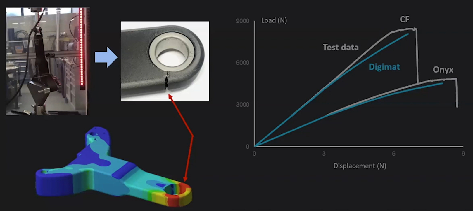
Step 3 – Manufactured part performance
FEA results showed maximum strain at the top lifting ring, validated by tensile tests (top left). There was also good agreement between Digimat results and the physical test data for strength and modulus (graph at right).
Failure in the Onyx-only tensile test part was at a load 25% higher than the maximum predicted in the simulation, but this was deemed an insufficient factor of safety. Using simulation results for the second part, says Lietaer, “we were able to show, that by adding only a couple of layers of continuous carbon fiber in the failure location, the stiffness was almost doubled to exceed 7 kilonewtons, meeting the required safety factor of 5.” Thus, he adds, this safety factor is sufficient to account for any uncertainty in actual maximum load seen in service as well as any variability in the part manufacturing, allowing the 3D-printed part to be safely deployed in Danfoss operations.
Optimize future printed parts
The next step is to optimize printed parts. “You can use Hexagon’s MaterialCenter platform,” says Lietaer, “to store and track any data from the workflow presented here.” This includes batch information for fiber and matrix materials, which printer was used and whether multiple parts were printed, as well as parameters such as print temperature and speed.
“It is also possible to store material test data used for simulation but also as-printed data such as tensile tests and metrology scans for dimensional accuracy,” he adds. “In this way, you centralize all of that data for wide access and use. For example, say some parts are failing prematurely. Using MaterialCenter, you can trace the parts and compare data to perhaps find the commonality in a specific batch of materials or a certain machine which needs maintenance. You can also compare the test data to identify which print parameters produce the best part performance. Thus, it is possible to optimize materials, machines and print processes, as well as designs for future parts.”
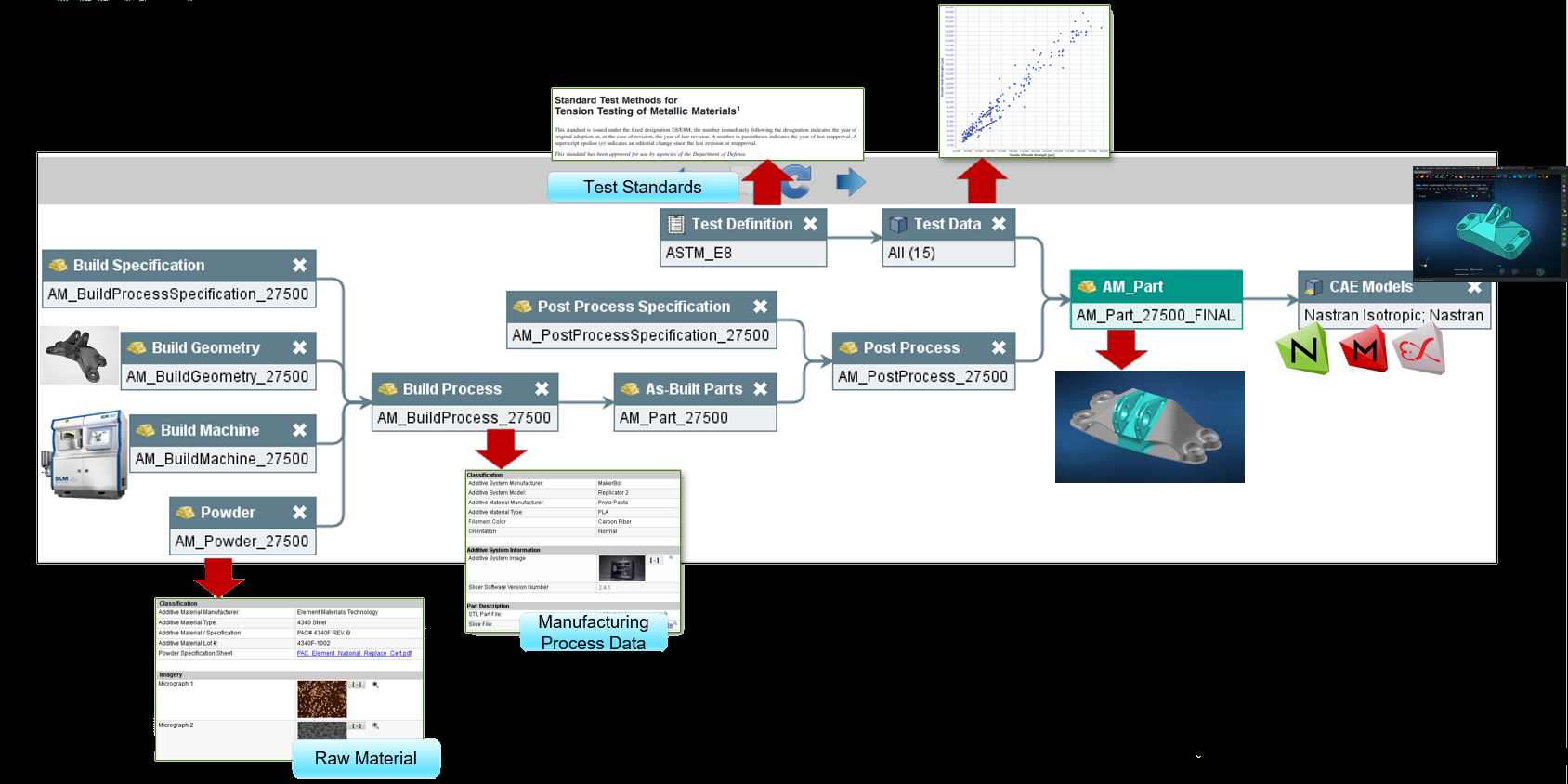
MaterialCenter can track all data from materials, print process and post-print inspection, as well as test data used for materials input, calibration and validation. This data can then be analyzed to help trace root cause in the case of future part failures or to identify optimized print parameters.
About the Author

Oliver Lietaer
Olivier Lietaer joined Hexagon (Stockholm, Sweden) in August 2016 as additive manufacturing (AM) business development engineer, where his main role is to connect the AM industry needs to the Digimat Development team, including the key tasks of accelerating new materials development, simulating the printing process and predicting the as-printed part performance. Prior to joining Hexagon, Lietaer served as R&D engineering team leader at Safran Aero Boosters (Liège, Belgium). He holds a PhD in applied mechanics from the Université Catholique (Louvain, France).


.jpg;maxWidth=300;quality=90;format=webp)


Related Content

Top 10 Considerations When Buying a CNC Machine for Composites
For a CNC machine to continue to meet or exceed a company’s needs, it must be built and spec’d with these needs in mind.
Read More
The making of carbon fiber
A look at the process by which precursor becomes carbon fiber through a careful (and mostly proprietary) manipulation of temperature and tension.
Read More
PEEK vs. PEKK vs. PAEK and continuous compression molding
Suppliers of thermoplastics and carbon fiber chime in regarding PEEK vs. PEKK, and now PAEK, as well as in-situ consolidation — the supply chain for thermoplastic tape composites continues to evolve.
Read More
Composites end markets: Aerospace (2023)
With COVID in the past and passengers flying again, commercial aircraft production is ramping up. The aerocomposites supply chain is busy developing new M&P for an approaching next-generation aircraft program.
Read MoreRead Next

From the CW Archives: The tale of the thermoplastic cryotank
In 2006, guest columnist Bob Hartunian related the story of his efforts two decades prior, while at McDonnell Douglas, to develop a thermoplastic composite crytank for hydrogen storage. He learned a lot of lessons.
Read More
CW’s 2024 Top Shops survey offers new approach to benchmarking
Respondents that complete the survey by April 30, 2024, have the chance to be recognized as an honoree.
Read More
Composites end markets: Energy (2024)
Composites are used widely in oil/gas, wind and other renewable energy applications. Despite market challenges, growth potential and innovation for composites continue.
Read More