
All-composite ROTORwing prototype UAV
Composites enable construction, and handle unique VTOL loads, of unmanned aerial vehicles’ helicopter-to-airplane conversion.
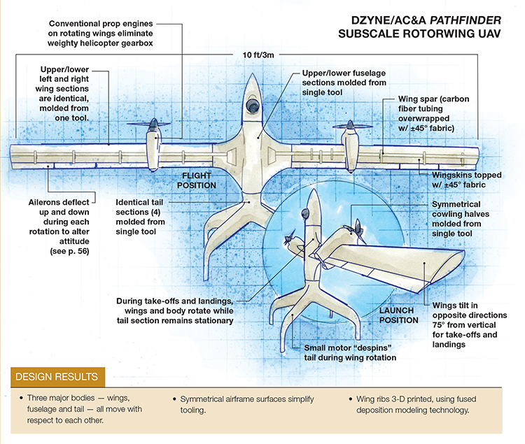
Dzyne/AC&A Pathfinder ROTORwing UAV Illustration: Karl Reque
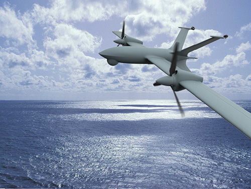
An artist’s conception of the ROTORwing in forward flight, after vertical take-off. Source: Dzyne Technologies
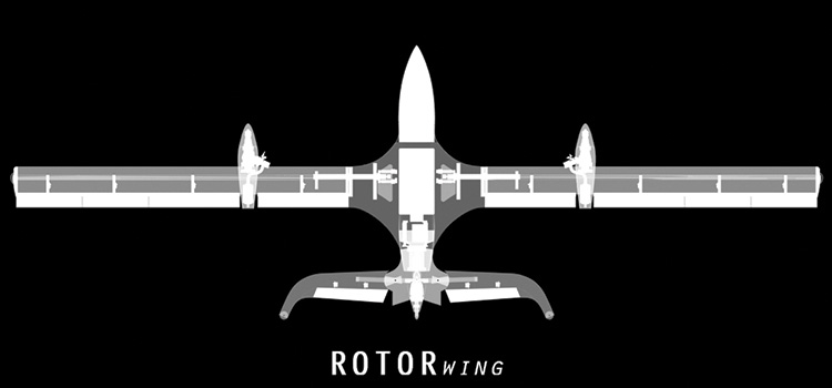
This graphic indicates the normal flight position for wings and tail. Note particularly the position of the tail fins, which have rotated forward and are locked in horizontal position. Source: Dzyne Technologies
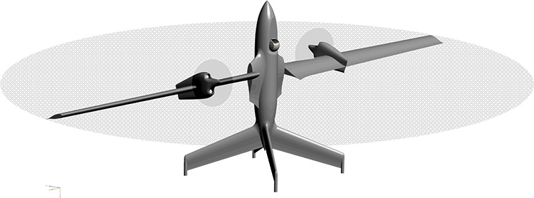
This graphic illustrates ROTORwing’s VTOL lift-off configuration. The position of the ailerons during rotation tilts the attitude of the inscribed rotational circle, which changes the craft’s flight direction. Source: Dzyne Technologies


Design Results:
- Three major bodies — wings, fuselage and tail — all move with respect to each other.
- Symmetrical airframe surfaces simplify tooling.
- Wing ribs 3-D printed, using fused deposition modeling technology.


Established in 2012, Dzyne Technologies (Reston, Va.) has achieved considerable success in engineering innovations, including a patented “roadable” submarine and several long-range, vertical take-off-and-landing (VTOL) flying machines. When the company launches its carbon fiber composite ROTORwing prototype unmanned aerial vehicle (UAV) in July 2014, it won’t be just another UAV. Unlike many conventional UAVs, the 10-ft/3m wingspan ROTORwing technology demonstrator will need neither runway, catapult nor net for launch and recovery. Called Pathfinder, it was designed at Dzyne’s Irvine, Calif., facility under contract to the Air Force Research Laboratory (AFRL, Wright Patterson Air Force Base, Dayton, Ohio). The prototype demonstrates the flight mechanics of Dzyne’s basic concept.
Spin power
“The principle behind ROTORwing is using the wings as rotors, and the flight engines to power the rotors,” explains Mark Page, Dzyne’s cofounder and chief scientist/VP. From a stationary position, tail on the ground, the ROTORwing will lift off straight up, in VTOL style. To prepare for take-off, ROTORwing first rotates its wings from the flight position (the wing chord parallel to the fuselage) in opposing directions, to the hover position, 75° off the fuselage’s 0° axis (vertical, in launch position). This wing rotation orients the plane’s two propellers in opposite directions, which causes the rotor-wings and upper fuselage to spin while the four-finned tail unit remains stationary on the ground.
When the wings and body motion reaches 60 rpm (1 revolution per second), the flaps (ailerons) are deflected down and the aircraft leaps into the air. A small motor in the tail “de-spins the tail” during flight — that is, it maintains the tail’s position and prevents it from spinning with the fuselage, explains Robert Godlasky, Dzyne’s ROTORwing chief engineer. Because it does not spin, the tail houses the aircraft’s navigation system. Directional control at this stage is provided by deflecting the ailerons down on one side of the revolution and up on the other. This tilts the “disk” described by the rotating wings (see graphic on right, p. 56), altering the flight path as requested by the pilot on the ground.
At a height of 2,000 ft/610m, the wings rotate forward to flight position, the wings and fuselage stop spinning, the tail unit locks into position and the Pathfinder then flies like a conventional airplane at scale speeds between 40 and 100 knots. (Scale speed is the speed the scale model will go in relation to the full size model. In this case, scale speed is about 10 times that of the full-size vehicle, or 400+ knots.) To initiate landing, the wings and fuselage are programmed to abruptly pull-up into a vertical climb at full speed and begin the transition back into the rotor wing configuration to allow a vertical landing — enabling the UAV to touch down gently on its tail.
“The innovation is that it matches highly efficient, long-endurance flight with vertical takeoff and landing, without needing a giant gear box between the engine and the rotor,” Page points out. In a conventional helicopter, the gearbox and tail rotor weigh about three times what the engine weighs. This airplane eliminates all that by spinning the wings. “We’ve got an engine on each wing … like a totally normal twin-engine airplane. The ROTORwing converts from a helicopter to an airplane using very small gearboxes between each assembly — wings, fuselage and tail — each of which can move independently of the others.” The result is a huge savings in weight.
Unusual stressors
Godlasky points out that the imposed loads are significant during lift-off: “When the wings are spinning one revolution per second, that force tries to eject the wings from the fuselage,” he says. “In addition to that, you’re pulling up to 2Gs momentary thrust to initiate climb. So you have the thrust load in addition to the load from centrifugal force. In addition, there are some smaller loads because the propellers are spinning in multiple axes — rotating about their own axis and being accelerated in a circle around the fuselage. This generates large gyroscopic forces, as well.”
To determine what materials and design would best handle these unusual flight loads in the prototype airframe, Dzyne used the DS SolidWorks Simulation package from Dassault Systèmes (Velizy-Villacoublay, France).
Composites were attractive in terms of manufacturing, says Godlasky, because they “allowed us to mold shapes that would otherwise be nearly impossible to manufacture, including the hard edges and small, tight radii we needed.” Both carbon fiber and aramid fiber were considered for the reinforcements. “There are advantages to using aramids in certain applications,” Godlasky observes, “but in this vehicle, we were primarily looking for stiffness-to-weight ratio, rather than toughness.” Carbon fiber composites, at half the weight of aluminum, and one-sixth that of steel, offered the best stiffness-to-weight.
The prototype airframe was built to Dzyne specifications by AC&A (Lake Forest, Calif.), a vertically integrated manufacturer of large, complex composite parts and tooling. AC&A has onsite capability for 5-axis machining, waterjet cutting, climate-controlled lamination; a 7 ft by 40 ft (2m by 12m) autoclave (capable of 350°F/176.7°C temperatures and pressures as high as 275 psi/1.90 MPa); a 4-ft by 9-ft (1.22m x 2.7m) autoclave (650°F/343°C, at 250 psi/1.72 MPa); and a walk-in oven, 9 ft by 30 ft by 8 ft (2.7m by 9m by 2.4m), able to achieve cure temperatures of up to 650°F/343°C.
Symmetry déjà vu
For economy, the wing was conceived as a constant section — that is, one long rectangle — rather than a tapered configuration, and its pieces are symmetrical in shape. “Not only are the wings symmetrical in their upper and lower skins,” says AC&A’s manager Steve Smith, “they are symmetrical left and right. A single tool makes four separate halves: upper and lower/left and right wing. They are unique in that regard.” If a wing is damaged on the aircraft, the user does not have to keep right and left wings on hand as spare parts; one wing section will replace either the right or left wing.
Similar design simplicity made it possible for AC&A to make a single tool for each major assembly — not only for the wing sections, but also for the fuselage and the four tail fins. Aluminum tools were used “because they are about half the cost of a composite mold and adequate for the size,” says Smith.
For mold release, “we are life-long users of Frekote 700,” from the Loctite line of mold release agents from Henkel (Bay Point, Calif.), Smith says.
For all the skin sets, AC&A hand-layed carbon fiber prepreg from Axiom Materials (Santa Ana, Calif.), made from bidirectional 2x2 twill T300 (Toray Carbon Fibers America, Flower Mound, Texas) and Axiom AX 5201 toughened epoxy in a balanced laminate and ply schedule that Smith describes as “only a couple of plies.” The wings have a ±45° orientation on the outer skin for torsional stiffness, Godlasky says.
Each wing has four actuators, or actuator-controlled ailerons (ailerons and actuators are visible in main drawing, p. 54), made from the same materials and process. “In VTOL mode, the ailerons are used for collective control (more or less lift) and cyclic control (tilting the rotor) of the VTOL function,” Godlasky explains. “As the rotor rotates around the body, the ailerons change pitch in every quadrant in order to make the helicopter pitch forward or roll right or left. For every revolution, these servo-controlled actuators must go to full up/down position per second for directional control.”
Additional composite structures include a nose cone that is bonded to the fuselage and contains flight electronics and surveillance sensors, as well as the cowlings for the engines. These elements are each made in upper and lower sections, from the same materials and process.
All parts were vacuum-bagged and cured in AC&A’s autoclave to the industry standard of 250°F/121°C at 90 psi/0.62 MPa for two hours. Autoclave cure was indicated, Godlasky says, because of “some tight corners in the part that I think would be difficult to mold without pressure.”
Rivetless bonding
The skin sets and other parts — about 40 in all — are bonded together with Henkel’s Hysol 9330.3, a Loctite EA (epoxy adhesive). The thixotropic formula is said to have high peel strength and excellent environmental durability. Bonding of the parts is, of course, critically important because of the centrifugal and gyroscopic forces applied during lift-off and landing. “We didn’t use rivets, but we designed the geometry of the mating pieces — the joints — to minimize peel,” Godlasky says.
Bonded parts include the cowlings; two wing spars that are off-the-shelf unidirectional carbon fiber tubes overwrapped with ±45° fabric and machined to size; and bulkheads inside the fuselage made from machined aluminum billets. Notably, six wing ribs (three per wing) were 3-D printed by AC&A, using Fortus 900mc fused deposition modeling equipment (supplied by Stratasys, Eden Prairie, Minn.), from acrylonitrile butadiene styrene (ABS). The ribs were bonded across the 0.75-inch/19-mm chord of the wingskins. The 3-D printing technology enabled dimensional fidelity within 0.007-inch/0.178-mm per layer, directly from CAD 3-D models, Smith says.
AC&A assembled the first article, a static model, but Dzyne assembled the flight-test article.
Scaling up for success
Dzyne expects a production contract from AFRL, pending a successful flight test. At that time, the carbon fiber composite airframe design will be scaled up for ROTORwing production models. Page says the full-size UAV will have a 25-ft/7.6m wingspan, weigh only 250 lb/113 kg and carry 35 lb/15.8 kg of payload for 20 hours or 70 lb/31.8 kg for six hours.


Related Content

Plant tour: Aernnova Composites, Toledo and Illescas, Spain
RTM and ATL/AFP high-rate production sites feature this composites and engineering leader’s continued push for excellence and innovation for future airframes.
Read More
Plant tour: Airbus, Illescas, Spain
Airbus’ Illescas facility, featuring highly automated composites processes for the A350 lower wing cover and one-piece Section 19 fuselage barrels, works toward production ramp-ups and next-generation aircraft.
Read More
Plant tour: Collins Aerospace, Riverside, Calif., U.S. and Almere, Netherlands
Composite Tier 1’s long history, acquisition of stamped parts pioneer Dutch Thermoplastic Components, advances roadmap for growth in thermoplastic composite parts.
Read More
Otto Aviation launches Phantom 3500 business jet with all-composite airframe from Leonardo
Promising 60% less fuel burn and 90% less emissions using SAF, the super-laminar flow design with windowless fuselage will be built using RTM in Florida facility with certification slated for 2030.
Read MoreRead Next

Next-gen fan blades: Hybrid twin RTM, printed sensors, laser shock disassembly
MORPHO project demonstrates blade with 20% faster RTM cure cycle, uses AI-based monitoring for improved maintenance/life cycle management and proves laser shock disassembly for recycling.
Read More
Cutting 100 pounds, certification time for the X-59 nose cone
Swift Engineering used HyperX software to remove 100 pounds from 38-foot graphite/epoxy cored nose cone for X-59 supersonic aircraft.
Read More
Scaling up, optimizing the flax fiber composite camper
Greenlander’s Sherpa RV cab, which is largely constructed from flax fiber/bio-epoxy sandwich panels, nears commercial production readiness and next-generation scale-up.
Read More