
The need for process modeling in filament winding applications
A discussion of how temperature, mandrel material and thickness, plus other factors affect the outcome of repeatable filament-wound composite shell manufacturing.


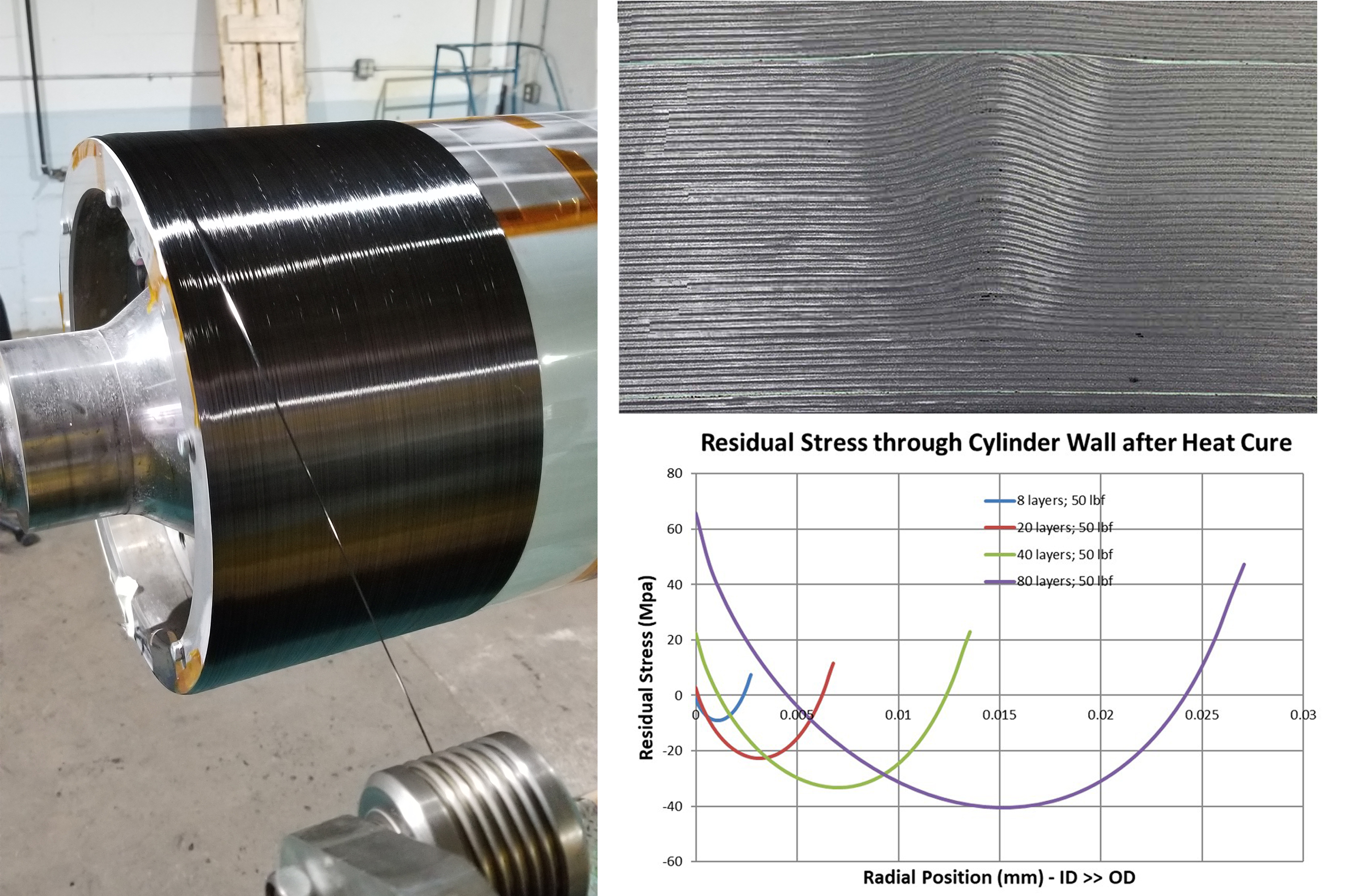
Source | Lawrie Technology Inc.
Filament winding is a common and enabling manufacturing process for producing composite items such as pressure vessels, driveshafts, electrical fuses and numerous other bodies of revolution. Fiber architecture is chosen to suit the application — for example, driveshafts favor 45° helical layers while pressure vessels use more ~90° hoops. For these and many other applications, structural design and winding equipment are highly developed; however, the filament winding process involves many more complexities than are commonly considered. This leads to serious industrial shortcomings in the performance and repeatability of filament-wound shells, but these can be addressed by process modeling.
This article will explore current analysis techniques, as well as manufacturing and materials considerations, and why these support the need for process modeling using examples including pressure vessels, permanent magnet motor (PMM) rotors, driveshafts and deep sea submersibles.


Issues with common structural analyses
There is a vast library of analytical and numerical methods for optimizing the performance of filament-wound composite shells. These typically assume the wound laminate has good quality and can take advantage of published lamina properties. Unfortunately, laminates commonly have fiber waviness, buckling and voids because optimizing the inherently nonlinear stress state during the winding process is complex and not well understood.
A linear approximation to process modeling is common, and will use fiber tension, radius of curvature and fiber angle to establish the radial pressure on the mandrel during winding. If the radius of curvature is large compared to the desired wall thickness, then the mandrel interface pressure is typically calculated by multiplying this first layer pressure by the number of layers. This type of analysis can be refined by estimating the actual radial position of successive layers and calculating the pressure gradient through the wall thickness. In the case of a modern hydrogen pressure vessel, this approach might be used to determine the air pressure required to inflate its thin polymer liner, avoiding collapse as successive layers of carbon fiber are added.
Note that typical composite laminates produced via vacuum bagging, autoclave cure or hydraulic presses using unidirectional (UD) or fabric reinforcements have fiber volume fractions (Vf) varying from 25-75%. These processes feature a constant through-thickness pressure applied during thermal cure of the laminate. In filament winding, however, the layer thickness will decrease — and Vf increase — with increasing pressure on the laminate. Thus, analysis of the filament winding process is actually a study of the mechanics of “growing bodies” — the pressure on the mandrel grows as the wall thickness grows.
Tooling is only at the inner diameter (ID) — traditionally, there is no hard tooling at the outer diameter (OD) — and this is frequently a removable mandrel, but it could also be a plastic or metal liner for pressure vessels and the metal rotor for a PMM. As the required layer count grows, the contribution of the middle layers to the mandrel interface pressure reduces because the as-wound layer tension — and radial position of the middle layers — changes with the addition of later layers and their additional pressure.
This phenomenon is exacerbated in thick filament-wound composites like naval submersible structures. In these components, the middle layers are wound with tension and a corresponding hoop stress, but can lose this entirely and eventually buckle under the continuing radial pressure of the later layers. A schedule to reduce tension can improve this slightly but cannot avoid the highly nonlinear nature of the process. Wrinkling, waviness and buckling are therefore a common finding in thicker composite shells.
For thin-walled shells applied to PMM rotors, although they are unlikely to experience complete loss of circumferential tensile stress in the middle layers during winding, it is common to see a ~20% reduction in overall containment pressure compared with what is predicted using a linear calculation.
Challenges of a thermal cure
The mandrel interface pressure has been discussed above as an important process parameter. For most filament winding applications, the product must be wound, cured and removed from the mandrel so that the next part can be made on the same tooling. Part removal requires the interface pressure after curing to be zero, and a small gap between part and tooling is preferable. Usually achieved following thermal cure, this requires control over another set of parameters including mandrel material and thickness plus cure temperature.
For hoop-wound carbon fiber, the hoop coefficient of thermal expansion (CTE) is close to zero, so any metallic mandrel material can work. However, applications like pressure vessels and driveshafts also require helical layers — windings at angles <90°. These layers produce less interface pressure for a given fiber tension when winding — note there is zero pressure at 0° or axial winding — and also have larger CTE values. To maintain process control and predict gaps after cure as well as finished dimensions when using helical or axial layers, the mandrel must still expand more than the composite laminate when heated. Thus, it is important to choose a mandrel material with a CTE larger than the proposed composite laminate to ensure positive interface pressure when hot and, after cooldown, the required zero pressure and gap for part removal. This could also be a factor when using fibers with a different CTE than carbon fiber.
However, cure also affects final part quality and should be included in the part’s analysis. As temperature increases in the oven, the uncured composite and the mandrel will grow together and reach an equilibrium diameter with a thermal component, adding substantially to the interface pressure produced by winding with tension. The uncured composite grows in diameter by virtue of both radial strain and circumferential strain but shrinks back after cure by virtue of circumferential strain only. This is because the cured laminate is several orders of magnitude stiffer through the thickness than the fiber and wet resin before cure. This is used to calculate the room temperature gap developed at the interface for part removal and reuse of the mandrel for the next wound part. (Most companies do this experimentally and not by process modeling.)
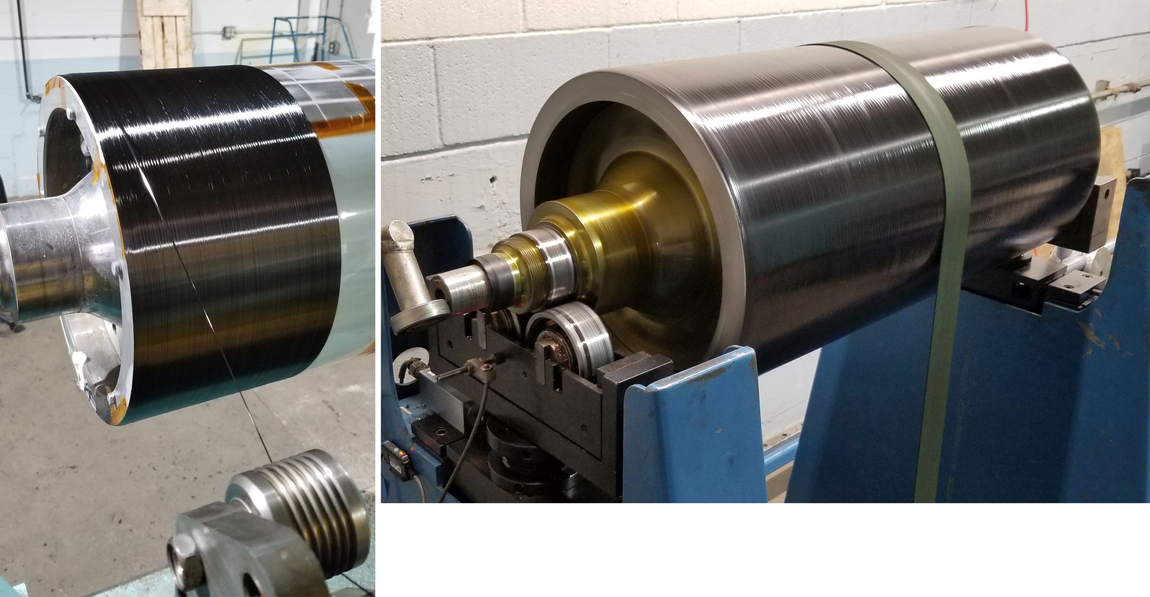
Figure 1. Ultra-high tension winding of a large diameter PMM rotor (left) and subsequent dynamic balancing (right).
In the case of a PMM rotor containment band, an elevated temperature cure will either remove the as-wound magnet consolidation pressure completely or greatly reduce it. For this reason, a room temperature cure is required for PMM rotor wrapping of very high-speed rotors.
Thus, the highly nonlinear winding process can easily compromise the integrity of the middle layers — particularly in thicker composite shells. A thermal cure with an appropriately expansive mandrel adds another nonlinear process on top of this. It is a mistake, however, to assume that the additional radial pressure applied by an expanding mandrel will remove any waviness or buckling produced by the winding process. While additional hoop tension is produced on the layers closest to the ID, the layers closer to the OD see much less of this new pressure and frequently remain wavy or buckled if they started out that way before heating.
Residual stress development
Although thermal cure can help produce the essential radial gap that allows reuse of tooling, this comes with a price. While a finished free-standing shell removed from tooling must have a net zero hoop stress, this always comprises a residual tensile stress at the ID and a residual compressive stress either in the middle of the shell or at the OD. Notably, these significant residual stresses can change the structural performance of pressure vessels.
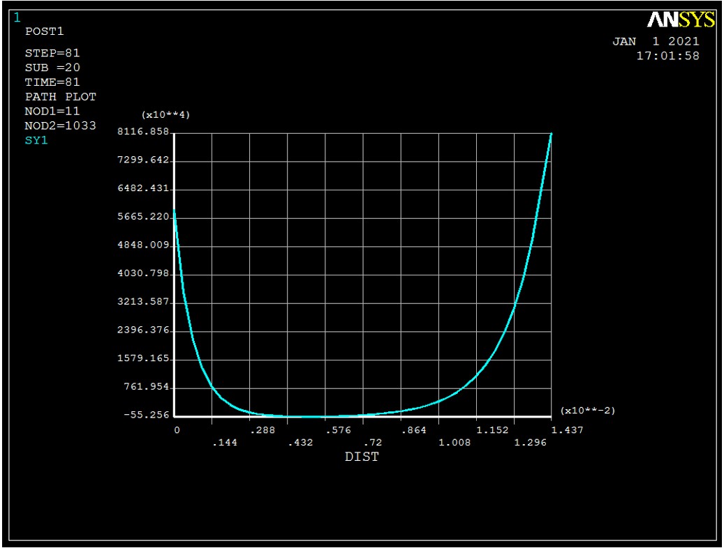
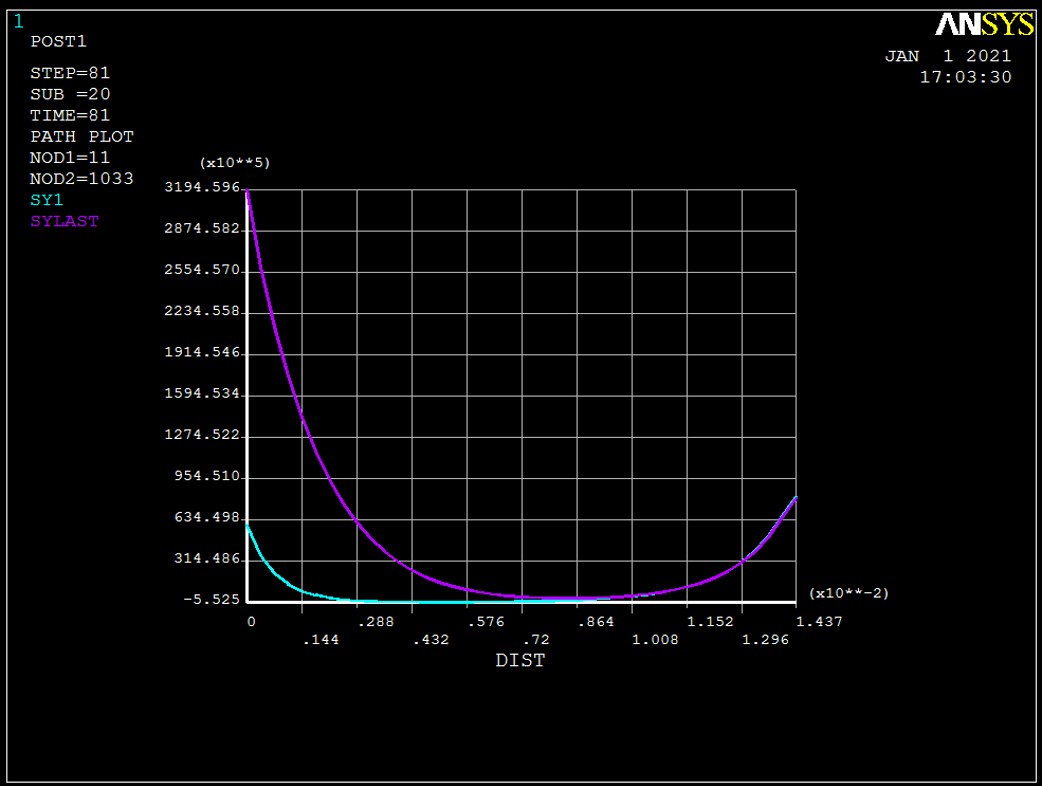
Figure 2. Hoop stress after winding (teal, top) and after heating (purple, bottom) using 10 lbf fiber tension, 250°F cure and 14-millimeter wound wall thickness. The vertical axis has been re-scaled in the bottom graph. Note the mid-thickness compression remains after heating.
Fig. 2 shows the nonlinear distribution of hoop stress through the wall after winding an arbitrary 14-millimeter-thick carbon fiber shell at 90° on a 300-millimeter-diameter steel mandrel with a 12-millimeter wall thickness. Fiber tension was 10 pounds force (lbf) and cure temperature was 250°F. The predicted hoop stress at the ID after winding was 60 MPa (8.7 ksi) and 319 MPa (46.3 ksi) after heating, while at the OD it was predicted to be 81 MPa (11.75 ksi) after winding and remained unchanged after heating. Most interestingly, almost half of the wall thickness is subjected to hoop compression after winding is complete, and some of this remains after the addition of temperature. This snapshot of hoop stress at temperature is important because the distribution remains after solidification and cooldown such that buckled fibers are now a permanent part of the rigidized shell. Also after cooldown, residual stress develops, and the composite diameter will reduce somewhat depending on the shell CTE in the circumferential direction.
Expedients used to alleviate the issues with thick shell waviness have included curing small fractions of the thickness sequentially — adding days to the process — followed by machining the OD of the cured section. This provides a smooth surface to begin winding the next section and removes the residual stress at the OD each time. The result is a new residual stress state and a reduction of the measured ID. Because the whole shell changes in dimension, quite large dimensional tolerances are required.
This approach of winding and machining successive sections appears to have been used on the deep sea submersible Titan (see discussion of thick-walled shells below). Fig. 3 shows a 25-millimeter-thick section that is buckled. Note the white lines above and below the buckled section that indicate machined surfaces. This extensive buckling develops when winding at the 2-3 lbf tension likely used for Titan (see discussion in sensitivity study below). Fig. 3 shows one of five cured 25-millimeter-thick sections. Alternatively, 25 cured sections of 5-millimeter thickness could have been used to avoid buckling with very undesirable cost and logistical implications, or preferably, a good process model could have been used to optimize the fiber tension for winding the entire 125-millimeter-thick laminate in a single step without distorted layers or secondary machining.
Material considerations
Reducing cost and improving throughput has become a key consideration for many filament winding applications. Pressure vessels for hydrogen-powered vehicles and for spacecraft are driving the need for higher performance and production rates while composite rotor/stator sleeves for electric motors require higher rotational speeds and extremely high fiber tension to contain magnets in PMMs. Such advances are driving examination of winding materials and processes.
Carbon fiber is typically the material of choice and can be embedded — in descending order of cost — in thermoplastic (TP) tape or towpreg, thermoset (TS) towpreg or low-viscosity TS resin. These materials can also use a variety of carbon fiber tow sizes to control layer thickness.
TP tows and tapes. These are the most expensive options in terms of raw material and process equipment but offer the ability for in situ consolidation via laser heating without significant heat reaching the mandrel. Recent projects developing PMMs for aircraft propulsion have selected TP tapes because of this real advantage. However, suppliers of TP tapes tend to offer a maximum Vf of ~55%. For PMM rotors, this means fewer layers can be installed in the small air gap between the outer surface of the rotor (containing the permanent magnets) and the inner surface of the stator. For other applications where this is not an issue, using laser consolidation still could pose a challenge. Because consolidation happens layer-by-layer without heating in an oven, there is no thermal expansion in the mandrel to produce a gap upon cooldown for part removal. Whatever interface pressure is developed during winding will remain, and mandrel extraction will require other expedients such as collapsible tooling.
TS towpreg. TS towpreg is less expensive than TP tapes but requires a thermal cure. Note that for both TS towpreg and TP tows and tapes, the resin cannot flow during the “growing body” phase of winding. Towpregs, however, will allow inviscid flow at temperature and just before cure with a radial pressure and hoop stress outcome different than that obtained with liquid resin winding, but again is highly nonlinear. The principal benefit is cleanliness [CW editor: faster winding speed and the ability for new market entrants to reduce wound product variability are also reported], but a problem is that the layer-by-layer Vf cannot adjust to the local pressure during winding. At temperature and just before gel, there may be insufficient resin in the layer or an excess which cannot escape to the surface in the time available before gel. A towpreg optimized for filament winding might have a low viscosity at temperature and adequate residence time at that low viscosity, but it remains critical to specify a resin content in the towpreg suitable for the anticipated Vf variation through the wall.
Wet winding. The numerical modeling performed in Fig. 2 and also in the sensitivity study below assume wet winding with liquid TS resin such that resin can continually migrate through the layers to the surface as pressure is added and Vf increases. Depending on both the ID and the fiber tension, the interface pressure might grow to 20 psi or 5,000 psi! A UD Vf might be 52% for 20 psi and 75% for 5,000 psi, with large associated differences in layer thickness. Wet winding allows for this huge range. For PMM applications, an additional major benefit is that a room temperature cure is possible when winding with liquid TS resins such that void-free, variable Vf shells can be produced without mandrel expansion and loss of interface pressure. Thus, liquid resin processing may be messier but remains the gold standard for many applications.
In summary, of the three major material choices, liquid TS winding allows for variation in layer thickness and Vf through the wall without voids regardless of diameter or wall thickness. TS towpreg does not allow for in-process Vf tailoring but is cleaner, possibly faster, requires less labor and can be appropriate for smaller wall thickness applications. TP tows and tapes don’t require any cure steps and provide the cleanest process without the possibility of layer wrinkling but may not provide the high Vf and high specific strength some applications demand.
Analysis considerations for large, thick-walled shells
The background provided above highlights the fairly complex modeling required to capture all aspects of the filament winding process. Understandably, many winding applications are developed using a seat-of-the-pants approach. For example, when a satisfactory result is obtained, the quality assurance documents simply require that nothing changes. However, this is unsatisfactory when the product is a one-off or when the tooling or part investment is very high.
A well-engineered composite winding process for large-diameter wound shells with thick walls would benefit from knowing in advance the gap possible for mandrel extraction and the fiber tension required to avoid any layer buckling, as well as an estimation of residual stresses. Large hydrogen storage vessels are an example, where roughly two-thirds of the tank wall is wound at 90°. While a liner provides the inner mold line and does not have to be removed, avoidance of buckled layers and voids is obviously desirable to maximize strength and minimize cost.
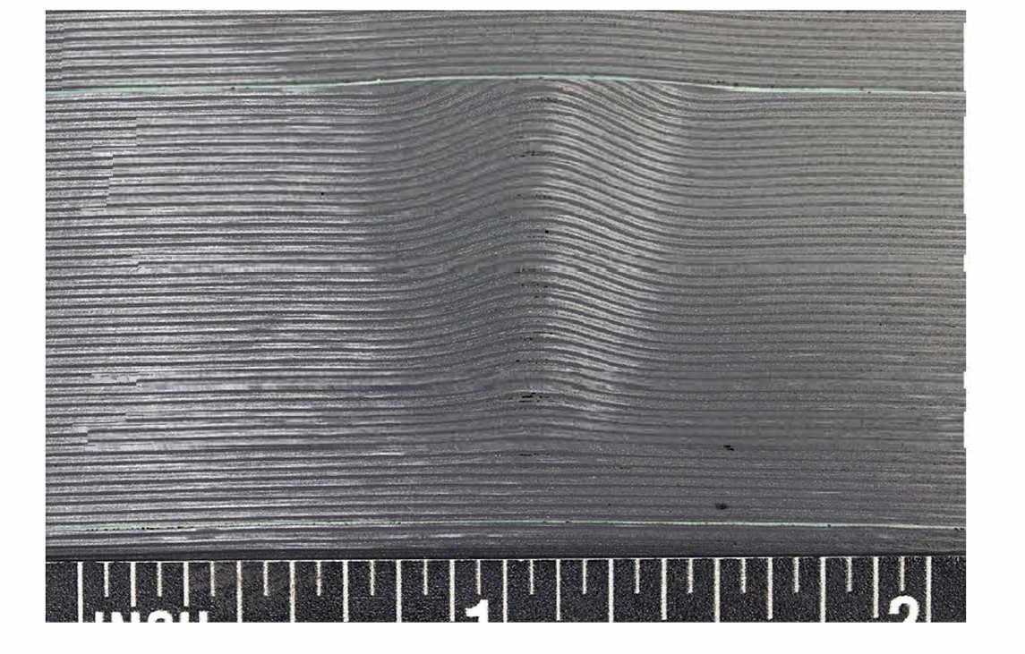
Figure 3. Wrinkles in Titan V2 hull trimmed end. Source | “Materials Investigation of the Experimental OceanGate Submersible Titan” by the U.S. Coast Guard Marine Board of Investigation, Sep. 25, 2024.
Deep sea submersibles are another example. Due to its failure in June 2023, the Titan is the most well-known and featured a thick carbon fiber composite shell. Its failure was a tragic event with extensive negative publicity. This column does not purport to examine the facts involved but will use the Titan’s rough dimensions as a process example. Deep sea submersibles are a perfect application for filament-wound carbon fiber because of the low weight in water, the possible huge specific strength and stiffness and the outstanding fatigue performance of an optimized fiber-dominated design. This comment flies in the face of public opinion in the aftermath of the loss but remains true. It is probable that design and analyses performed for Titan were competent and well executed, but producing what was designed was a real challenge as evidenced by the significant buckling visible in Fig. 3. This image shows a recovered 25-millimeter-thick section with distorted layers, which are not capable of providing the hoop compression strength required at the ocean depths for Titan missions. The vessel had a total wall thickness of roughly 125 millimeters with five 25-millimeter sections cured and ground sequentially.
Another example of a carbon fiber composite shell with roughly the same diameter as the Titan is a proposed U.S. Navy nuclear submarine driveshaft. With large shaft power and low revolutions per minute (rpm), the ~18-meter-long shaft requires a majority of helical layers with supplemental hoop and longitudinal layers to avoid torsional buckling and resonant frequencies. At approximately 1.25 meters in diameter, the consolidation pressure possible from fiber tension is much smaller than typical in smaller diameters, and the large wall thickness provides the perfect conditions for extensive layer buckling and voids. Removal of an 18-meter-long mandrel is also a large risk without process modeling and optimization unless the mandrel is collapsible
Sensitivity study demonstrates issues
The graphs below show analysis results from a sensitivity study designed to model geometries similar to the above examples of the Titan, hydrogen storage tanks and the naval driveshaft. It considers only hoop layers and a 250°F cure for a wet wound, standard modulus 24K carbon fiber. The mandrel used in the simulation was a 9.5-millimeter-thick steel cylinder chosen to minimize weight and just avoid collapse under the likely interface pressures developed. The fiber tensions studied varied from 2 to 50 lbf, and the number of wound layers varied from 8 to 80.
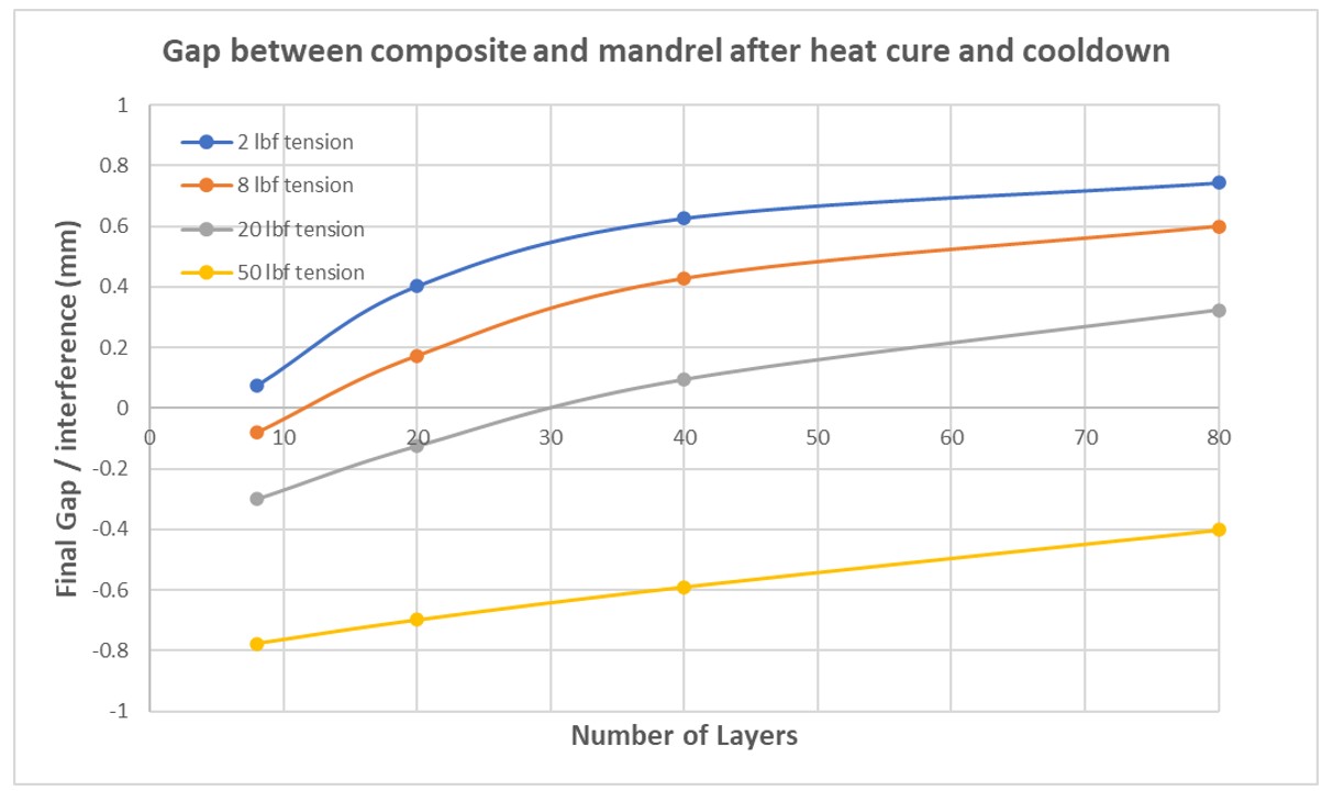
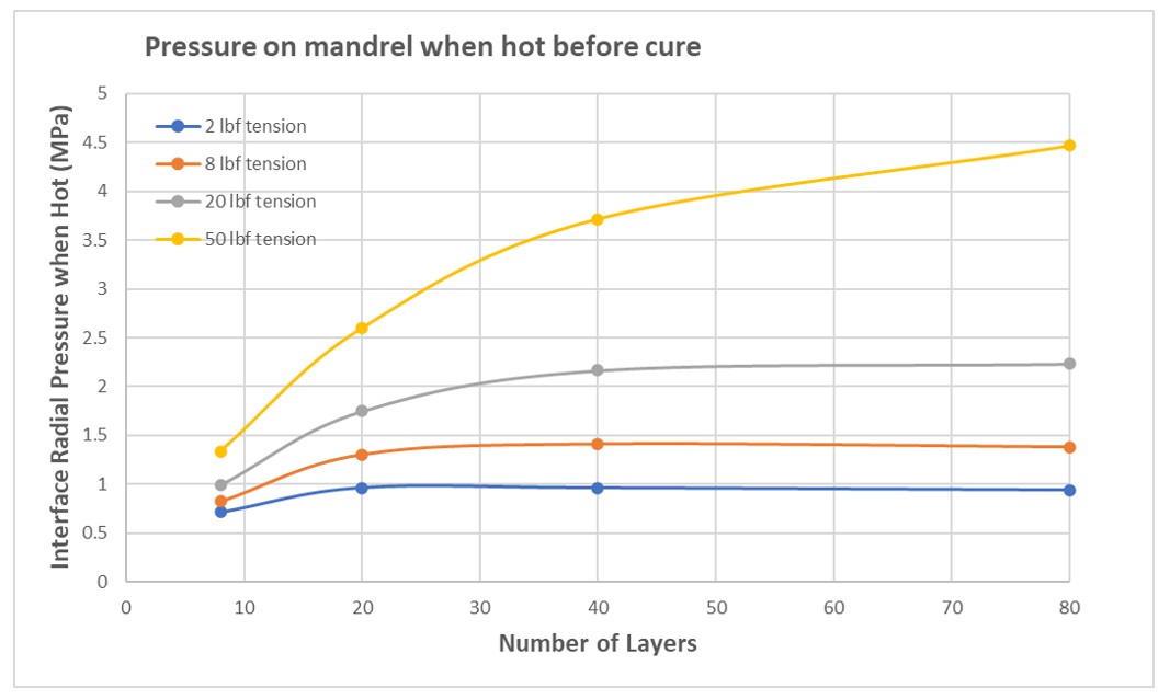
Figure 4. Gap achieved from mandrel after cooldown (top) and mandrel pressure just before cure (bottom).
The Fig. 4 (top) graph at right shows that at a 50-lbf tension (yellow curve), there is no shell thickness which can be removed from the mandrel because a significant radial interference remains in all cases. For a 20-lbf tension (gray), more than 30 layers are required for mandrel removal to be possible.
The next graph (Fig. 4 bottom) shows the pressure at the mandel interface at temperature and just before cure while the resin is still at low viscosity, but at that point the final fiber architecture has already been determined. For tensions below 50 lbf, the curves flatten with additional layers, suggesting they aren’t contributing to interface pressure. They are also still wet, and thus cannot support compression before cure, so they must buckle.
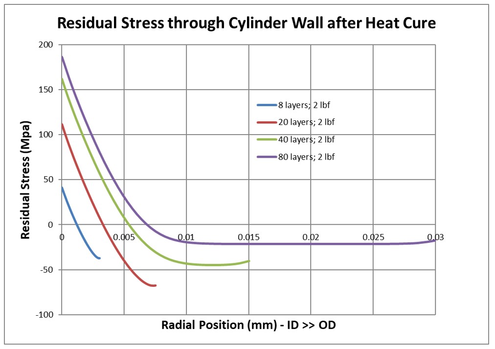
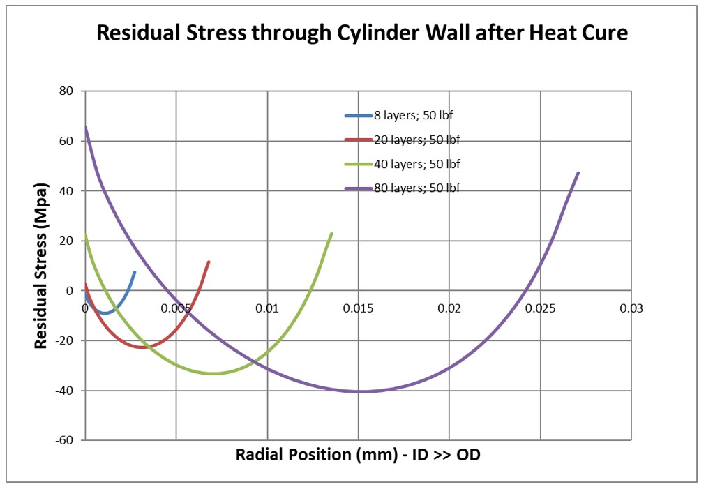
Figure 5. Residual stress development after cure and cooldown using 2-lbf tension (top) and 50-lbf tension (bottom).
Fig. 5 compares the residual stress developed for the range of shell thicknesses studied at winding tensions of 2 lbf and 50 lbf. The successive curves show residual stress with increasing layers moving right from the vertical axis.
At 2-lbf winding tension, for all shell thicknesses, there is much higher residual hoop tension at the ID and more modest residual compression at the OD. In contrast, the 50-lbf winding tension results in tensile residual hoop stresses at both ID and OD, while the mid-thickness material retains the residual hoop compression necessary to provide the required net-zero stress when the part is free-standing, off the mandrel.
Notably, this low winding tension is quite close to the typical 3-4 lbf tension that carbon fiber producers use as they package fiber at the end of the production line. An end user can certainly use this package directly in a winding process, but only up to a tension of ~10 lbf. Much beyond that and the tensioned line cuts through the package like a cheese wire and destroys the remaining material. The solution is to add tension after the fiber leaves the spool, and as indicated above, quite often a significant amount of tension is required to obtain a shell with unbuckled layers.
Discussion and conclusions
This study is only a snapshot of one part geometry. Note that cure temperature, mandrel material and thickness, plus other factors can also change the winding outcome. However, it is clear that higher tensions can improve every aspect of the wound shell’s quality, strength and dimensional accuracy. Notably, an accurate process model can reduce a typical 0.030-inch ID tolerance by an order of magnitude to 0.003 inch. Void-free, unbuckled shells will also result in higher strength with much smaller statistical variance and therefore enable lower cost products.
In the case of PMM rotors wound at high tension and with containment band thickness of 1-2 millimeters, buckled layers are unlikely but a 20% loss of anticipated containment pressure is common because of the nonlinear growing body behavior. A recent development rotor for an aircraft propulsion system required 50 lbf of tension on a 3K carbon tow resulting in the following stresses.

Stresses in winding 3K carbon tow with tension of 50 lbf for a development PMM rotor in an aircraft propulsion system.
Note that the last layer stress as installed on the cured rotor will double in magnitude as the rotor spins up to operating speed. This implies that rotor applications are now approaching the published strength of available carbon fibers and, thus, accurate understanding of the process is essential. In the case of pressure vessels storing compressed gases like hydrogen, an inflated mandrel must follow the growing interface pressure from winding to maintain the inner mold line exactly. In some cases, shop air at <150 psi will be insufficient to match the interface pressure necessary to avoid wrinkling.
In the case of submersibles, the highest hoop compression from the head of water they must withstand is at the shell ID, and a shell produced without distorted layers could have a significant pseudo-autofrettage (residual tensile stress) at the ID to improve performance — adding to the suitability of a well-made composite vessel in this application.
Another factor demonstrated in the sensitivity study presented here, the average shell Vf varied from 52.1% for 80 layers at a 2-lbf tension to 64.8% for 80 layers at a 50-lbf tension. Shell thickness varied in proportion. That difference highlights the challenge in winding with TP tapes or TS towpreg where the raw material has a fixed Vf as produced.
The mandrel geometry is also key for shells that are wet wound and thermally cured. If, as is very common, the machined mandrel does not have precise axisymmetry — i.e., the wall thickness varies — then the equilibrium geometry during cure will not be cylindrical at the interface. The implication in the case of pressure vessels, whether designed to withstand internal or external pressure, is that the in-service stress state will now include a serious bending component — a load component not included in traditional structural analyses.
It is frequently stated that advanced composite materials offer outstanding performance in myriad applications. This is often accompanied by caution against “black aluminum,” meaning that simply substituting a composite material for an isotropic metal in an identical geometry seldom produces a satisfactory result. In the case of filament-wound composites, being able to optimize fiber type, part geometry and layup angle is a major advantage, though it is just as important to simultaneously design the manufacturing process.
About the Author

Duncan Lawrie
Duncan Lawrie owns and operates Lawrie Technology Inc. (LTI, Girard, Pa., U.S.) specializing in advanced composite materials. In addition to new product development using high-performance fibers LTI also provides consulting services in the area of structural optimization, FEA and a well-equipped mechanical test facility.
Lawrie has a BS degree in mechanical engineering from Liverpool University and an MS in aeronautical structures from Cranfield Institute of Technology in the U.K. His long career spans work as a stress analyst in aerospace, wind turbine, chief engineer, product development engineer and product department engineer and more. Lawrie also built and flew a human-powered aircraft and was a founding member of the Kremer Prize Committee, responsible for the cross-channel flight of the Gossamer Albatross in 1981.


Related Content

Co-molding SMC with braided glass fiber demonstrates truck bed potential
Prepreg co-molding compound by IDI Composites International and A&P Technology enables new geometries and levels of strength and resiliency for automotive, mobility.
Read More
Otto Aviation launches Phantom 3500 business jet with all-composite airframe from Leonardo
Promising 60% less fuel burn and 90% less emissions using SAF, the super-laminar flow design with windowless fuselage will be built using RTM in Florida facility with certification slated for 2030.
Read More
Ceramic matrix composites: Faster, cheaper, higher temperature
New players proliferate, increasing CMC materials and manufacturing capacity, novel processes and automation to meet demand for higher part volumes and performance.
Read More
Troubleshooting thermoplastic composite stamp forming
Understand the basic science of TPC stamp forming, a manufacturing process steadily gaining momentum in aerospace and mobility applications thanks to its rapid forming, short cycle times and automated methods.
Read MoreRead Next

Carbon Axis XCell platform now combines AFP and filament winding processes
The compact, user-friendly composites manufacturing machine brings two complementary processes together on one platform for industrial users, R&D and technology development environments.
Read More
Dialing in composites performance via dynamic digital twins
Sport Dynamics Lab uses Flexdynamics testing, digital models and AI tools to compare designs, materials and systems, enabling optimization with potential for propellers, drones and vibrational structures.
Read More
Post Cure: 3D printed plastic, composite mouthstick designs assist limited-mobility users
Three M Tool and Machine has used its in-house additive manufacturing capabilities to rethink medical devices like mouthsticks, which must be stiff, lightweight and comfortable enough for everyday use.
Read More


