Revisiting the Fundamentals of Light Resin Transfer Molding (LRTM)
Sponsored ContentLike other closed molding composites processes, Light Resin Transfer Molding (LRTM) offers reduced waste and emissions, efficient materials use and a consistent and repeatable process. But LRTM requires less costly tooling and can still provide excellent cosmetics on both sides of a part in an efficient manufacturing process.
Share
Though it’s been around since the 1970s, resin transfer molding (RTM) continues to grow in popularity due to its ability to efficiently make strong and excellent quality parts in production quantities. Like several other composites closed molding processes, RTM offers virtually no material waste and a very clean production environment with far less HAP emissions in comparison to most open molding processes.
It’s also a more consistent and repeatable process that can produce parts with high strength-to-weight properties and dimensional conformity with aesthetically pleasing surfaces on both sides of a part. Light RTM (LRTM) has more recently increased in use because it can use simpler, lower cost molds that don’t have to contain high cavity pressure, yet still achieve short cycle times of as little as 20 minutes to mold a part complete, including initial curing, often with no subsequent finishing required.
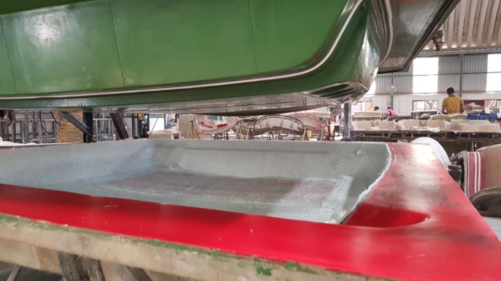
LRTM can produce large and complicated parts with excellent quality and accuracy.
LRTM is successfully used in several end markets served by the composites industry, including aerospace, trucks and buses, marine, wind energy and many others. An important factor in consistently producing high-quality LRTM parts is precision control of the resin infusion system that is so critical to good process control. Magnum Venus Products (MVP), a global provider of fluid movement solutions for over 80 years, revitalized the process by defining production details to save time, decrease cost, and increase part quality. Since the inception of LRTM, MVP has led the process development with novel techniques including Flex Molding, Infusion, and its latest process aptly named Fast Flow LRTM, which utilizes collapsible channels to decrease injection times. MVP provides a full-service solution to closed molding, from comprehensive training and support to extremely accurate injection equipment. Here’s more from MVP on the important aspects of the LRTM process and how to consistently mold high-quality parts in a production environment.
The LRTM Process
The LRTM process basically only requires an injection or proportioner system, a vacuum system and the mold itself. This is showing the Flex Molding process, a variation of LRTM, with a re-usable membrane counter mold. Flex Molding was developed by MVP to enable infusion of a part using an injection machine connected to pneumatic accessories that are loaded on a vacuum bag, re-usable membrane, or both.
A great attribute of LRTM is that the investment required for equipment and tooling is relatively modest. You ultimately just need an injection or proportioner system – such as MVP’s Patriot Innovator PLC Injection System – that meters and mixes the resin and catalyst and injects the mix into the mold, a vacuum system that seals and creates negative pressure between the mold and counter mold, and the mold itself.
The tooling consists of a base mold (“A” side) and a semi-rigid counter mold (“B” side). The base mold is built with a relatively stiff composite structure with a very simple steel reinforced framework. The counter mold is a thin 3-to-4-mm laminate with extra stiffness built-in around the flange where it mates with the base mold. The counter mold is built with two seals running around the peripheral flange. The outer seal is a neoprene or silicone ‘wing’ type seal that forms the primary vacuum seal. The inner silicone seal is a dynamic seal to prevent the injected resin from escaping from the mold into the flange area.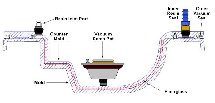
To make a part, after a release agent and gelcoat are sprayed into the base mold cavity, dry fiber reinforcement is loaded into the mold and the two matching mold halves are closed. Vacuum is then drawn between the inner and outer seals to hold the mold halves together. Once the vacuum pressure is verified, a resin and catalyst mixture is injected at low pressure (<1 bar or 14.5 psi) into a peripheral feed channel running around the entire edge of the component, just inside the inner seal.
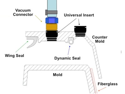
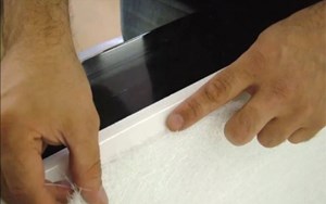
Flange detail for LRTM mold.
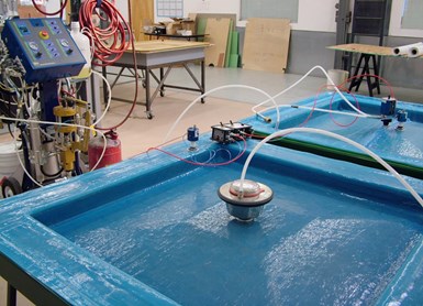
A vent is positioned at the final point of fill, usually in the center of the component, through which vacuum is drawn. On large molds or molds with complicated geometry, more than one exit vacuum point can be used. The mold cavity is evacuated at a slightly lower level of pressure than the vacuum seal. A catch pot is positioned at final fill point(s) to collect any excess resin that would otherwise be pulled into the vacuum system. This central vent is normally built into the counter mold.
The resin is injected through the counter mold into the resin channel running around the part along the dynamic seal, using either an MVP Autovalve or a simple 10-mm (.39 in.) injection tube connected to the appropriate injection ports. At the end of the injection, the injection tube is clamped off and the injection machine is disconnected. Vacuum is kept on the catch pot until the resin has cured. It is important to use an appropriate gel time to solidify the part. For example, if the injection time is 10 minutes, the gel time has to be 12 to 15 minutes. A shorter gel time will stop the resin flowing into the catch pot; a longer gel time will let too much resin go into the catch pot.
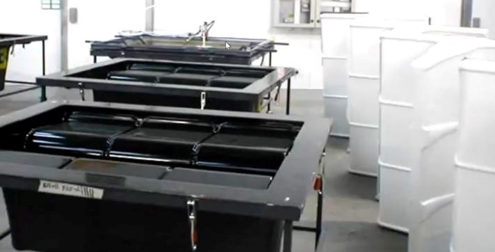
For families of parts a single counter mold may be able to be used on multiple base molds. This creates very efficient production if one base mold can be prepared while another is processing a part.
Equipment for Better LRTM Process Control
While LRTM can be executed with relatively simple pump, vacuum and tubing components, using more technically advanced equipment yields a higher quality and more repeatable process as well as shorter cycle and setup times. MVP has been designing products specifically for this process since its inception in the 1970s. Here are a few important ones that contribute to a productive and safe process:
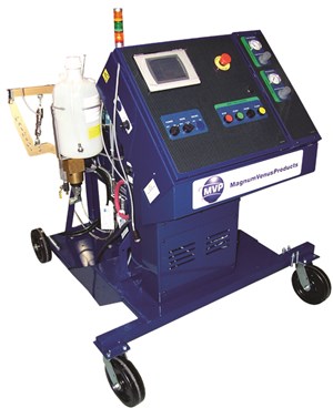
MVP Patriot Innovator Injection System with PLC.
Injection Unit – To consistently produce high-quality LRTM parts requires precise control of injection pressure and the mix ratio of catalyst to resin. The Patriot Innovator Injection System does both in one compact package. The unit is designed for injecting polyester, vinyl ester and methacrylate resins and catalyst at controlled pressures. The material mixing is done on demand at the injection head, and the catalyst ratio can be adjusted from 0.75% to 2.5%. The fully pneumatic automated control system regulates the number of pump strokes per injection to provide consistent material delivery and recirculation to maintain material consistency, helping make the process easier to execute and more efficient. Depending on how automated you want the process to be, MVP also offers a PLC control option. This provides exact control of shot sizes, reducing material waste and saving cost. The PLC option also comes equipped with RFID tracking for supplies and injection formulas for safer injections and increased accuracy.
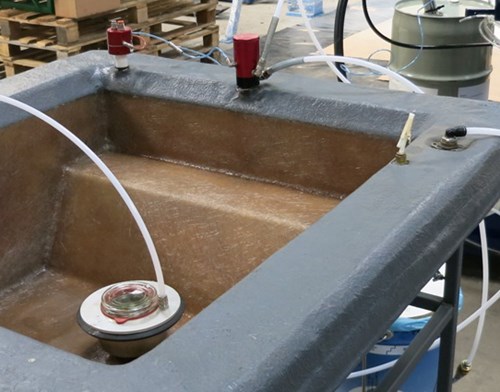
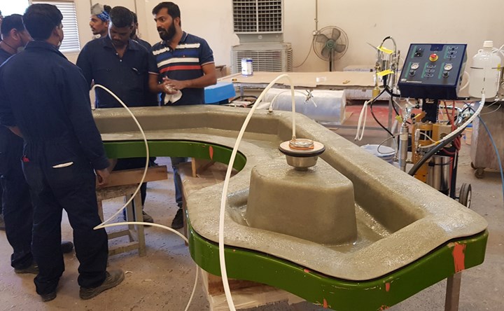
Using accessories like the Turbo Auto Sprue injection valve (back center of mold) and PPVS pressure sensors (left back) result in a more accurate and consistent process. The vacuum catch pot is shown at front corner of mold.
Pressure Sensing – Maintaining optimum injection pressure is important to achieving an efficient and safe process. Too little pressure prolongs fill time. Too much pressure can flex the mold and cause thicker than desired parts. It can also separate mold halves during injection or even damage the counter mold. MVP maintains precise pressure control with the Mold Pressure Guard feature that is built into the Patriot injection System and a PPVS pressure sensor. If there is too much pressure inside the mold, the pump automatically shuts off until the pressure is relieved. Once the pressure is normalized, it restarts injection
Precise Material Metering and Flushing – To maintain consistent product quality and reduce waste, you must precisely control the amount of material injected with each shot. You must also ensure that the injection line is clean and free of obstructions. If material is left in the line too long it will start to cure and cause inconsistent material flow or even clog the line. Using MPV’s Turbo Auto Sprue (TAS) injection valve at each injection port addresses both issues.
When injection begins, an air signal is sent to the valve, opening it. Once the MVP injection unit hits its preprogrammed stroke count, the machine automatically shuts off and sends a signal to close the valve. This provides precise control over the amount of material injected with each part. When the injection ends, a gel alarm activates if the operator fails to flush the machine. This will prompt the operator to initiate an injection line flush cycle, which forces about 300-cc of solvent into the line, through the valve and out to a flush bucket. This procedure is followed by a timed and adjustable air purge to ensure all solvent is out of the injection circuit and it’s ready for the next shot. A safety interlock ensures the flush cycle cannot be activated while the machine is in inject mode. This metering and cleaning system results in very minimal waste, a clean injection, and reusable valves and hoses.
Trouble-Shooting Common LRTM Problems
As much as using better injection equipment will ensure a more precise and consistent resin transfer cycle, there are still other factors to consider in achieving a high-quality and efficient LRTM process. Here are a few often overlooked aspects of the LRTM process that really matter:
Technical flange design – This is the most important element to ensure the mold and counter mold are clean and ready to use again after demolding a part. Proper flange design and processing includes:
- Using a vertical flange to easily close the large mold without using a clamp. This is common practice in Europe but less common in the United States.
- Using a 45-degree angle at the part border to precisely load glass into the mold.
- Cover the flange area when spraying gelcoat instead of using tape, which can be time consuming and expensive.
Careful cutting and placement of reinforcement materials will ensure a more consistent final product.
Loading reinforcement materials over the seals – Because fiber reinforcement is typically loaded into the cavity of the base mold but the seals are attached to the counter mold, it is easy to inadvertently position fiber reinforcement material in the flange space (between the inner and outer seals). This ruins the integrity of the cavity vacuum. Taking care to accurately prepare and use fiber reinforcement cutting templates helps prevent this problem.
Inconsistent reinforcement loading – Inconsistently loading or positioning fiber reinforcement material results in variable part quality. Be sure to have a well-followed procedure for where and how to place fiber reinforcements and use a pattern to cut the glass precisely.
Thermal variability – Inconsistent temperatures in the manufacturing facility or resin will also result in process variability, affecting material flow rates and other factors. Using MVP’s auxiliary heaters, thermocouples, and a resin recirculation system helps improve thermal consistency.
Poorly mixed additives – Additives such as fillers, pigments and promotors provide a variety of opportunities to enhance the properties of a LRTM part but can fall out of the resin if not mixed properly. MVP offers a line of mixers and recirculation circuits to maintain material consistency up to the injection head.
Selecting the proper injection points – It’s critical to select the proper injection points according to the part shape and size.
Thickness between part end and resin channel – Decreasing the thickness between the end of your part and the resin channel will regulate the resin flow when starting injection and will make it easier to trim the part after it’s demolded.
Mold construction – When constructing your mold, MVP recommends infusing a reusable calibrated part thickness instead of using sheet wax for large molds. This option is faster, six times cheaper, and the calibration part is reusable if building more than one counter mold. It’s also critical to have the right seal profile, especially for the resin channel. MVP recommends two dimensions to decrease resin waste. Lastly, decrease and standardize raw material on the mold and counter mold by using the same gelcoat, resin, and glass for both.
With its ability to manufacture aesthetically pleasing parts with very high strength-to-weight properties, and at very reasonable cost, LRTM is great choice to efficiently make a wide range of consumer and industrial products. With the right equipment and process controls, those products can be made to the highest quality standards time after time.
Please go here for more information on MVP Composite Application Products.
