


This blog is an online sidebar for the May 2020 feature, “Revolutionizing the composites cost paradigm, Part 2: Forming”, which discusses the RApid high-Performance Manufacturing (RAPM, pronounced “wrap-em”) program led by The Boeing Co. (Chicago, Ill., U.S.). RAPM is the “forming” part of DARPA’s Tailorable Feedstock and Forming (TFF) program to enable rapid, low-cost and agile manufacturing of small, complex-shaped composite parts.
Here, I simply wanted to provide some of the additional visuals and points for discussion that we didn’t have room for in the feature article. RAPM was split into three different material and process tracks: Resin infusion, thermoset prepreg and thermoplastic prepreg forming. We’ll follow that same division as we walk through some of the details of these parts forming trials here.


References include:
- SAMPE 2019 technical paper and slide presentation, “Fabrication of a Complex Part with Deep-Draw Sections by Resin Transfer Molding” by Thomas K. Tsotsis1, Gilbert Cespedes-Gonzalez2, Mario Wiener2, Leslie Cohen3, Dominic Calamito3, Stephan Costantino4, Florian Klunker4. 1The Boeing Company, Huntington Beach, Calif., U.S.; 2SGL Composites GmbH, Ried im Innkreis, Austria; 3HITCO Carbon Composites, Inc., Gardena, Calif., U.S. and 4Huntsman Advanced Materials, Basel, Switzerland.
- SAMPE 2019 slide presentation, “Process Modeling to Improve Tool Design and Part Quality for Resin Infusion” by Thomas K. Tsotsis.
- SAMPE 2020 technical paper, “Challenges of Aerospace Structural Part Geometries for High-Rate Compression Molding” by Aurele Bras1, Alejandro J. Rodriguez2, Richard Russell1, Timothy J. Luchini3, Travis Adams3, Adam Whysall1, Scott A. Rogers2, Scott Lucas2, Gail L. Hahn3. 1The Boeing Company, Saint Louis, Mo., U.S.; 2Solvay Composite Materials, Anaheim, Calif., U.S. and 3Solvay Composite Materials, Heanor, U.K.
- SAMPE 2019 technical paper, “Rapid High Performance Molding of Structural Thermoplastic Composite Parts” by Justin J. Schell1, Steven M. Shewchuk1, David Leach2, Trevor McCrea2, Ned Abrams2, Richard Postera2, Gail L. Hahn1. 1The Boeing Company, Saint Louis, Mo., U.S.; 2ATC Manufacturing, Post Falls, Idaho, U.S.
Resin infusion preform design
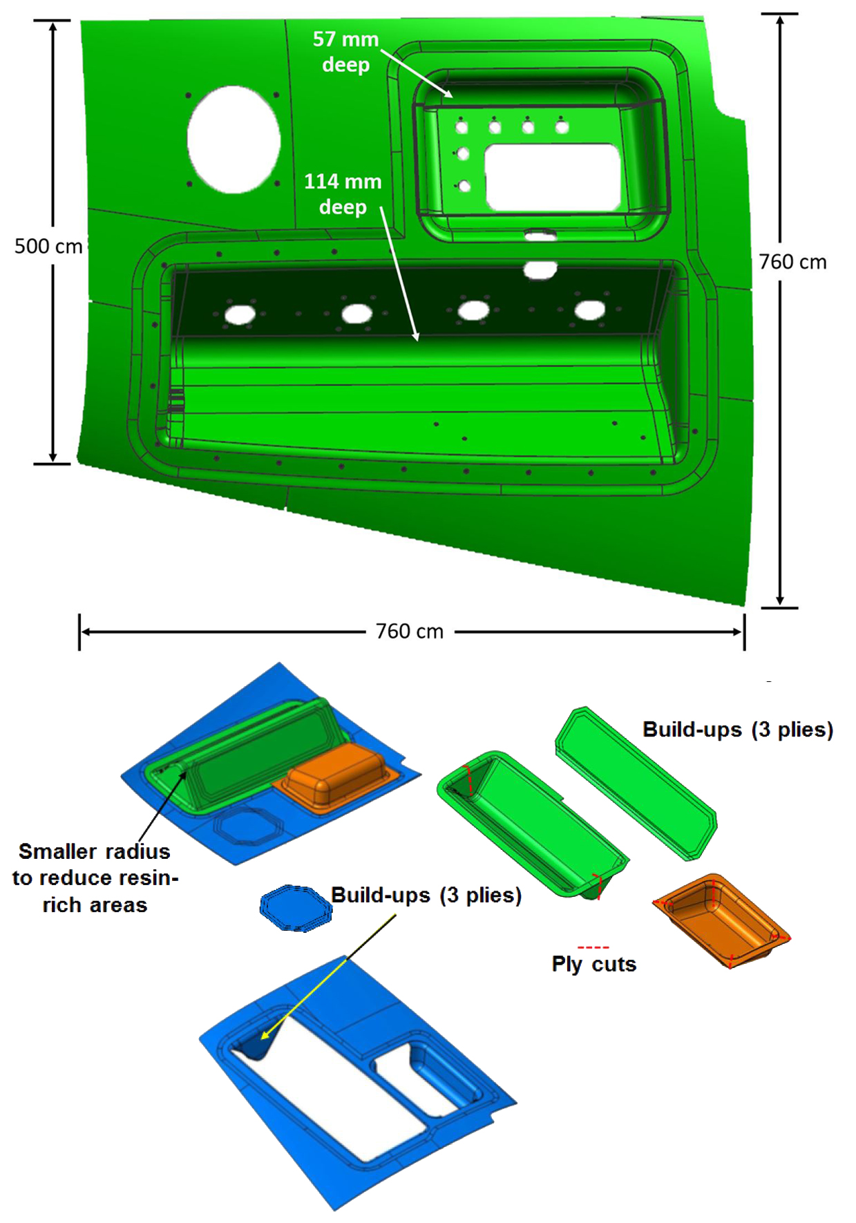
RI-RAPM-004 challenge part dimensions and NCF preform elements. SOURCE | Fig. 2, 3 and Slides 5, 7, “Fabrication of a Complex Part …” by Tsotsis, et. al.
As explained in the feature article, after molding the pathfinder parts in the initial Manufacturing Development trials, RAPM moved on to the RI-RAPM-004 deep-draw, double-pan challenge part. The part’s geometry was inspired by an actual part for a production platform that is difficult to fabricate — a pan assembly with two deep-draw sections as well as pad-ups around the deep-draw sections and the access hole.
Improvements in preforming were developed to show a path toward more efficient manufacture using resin infusion/resin transfer molding (RTM) than is possible with the previous state of the art using prepreg layup.
The non-crimp fabric (NCF) preform for RI-RAPM-004 was broken up into multiple sub-elements: skin, deep-draw sections, and the build-ups around the machined access hole and deep-draw sections. All fabrics were 400 grams/square meter (gsm) ±45° biaxial, except for the build-ups, which were 154-gsm unidirectional (UD). Different ply layups were used for the elements to achieve the designed panel thicknesses.
Even with 12 different NCF preform elements, a 2/3 reduction in piece count was achieved versus 66 cut pieces for the current part using prepreg. RAPM estimates this also reduces labor for this part — which mostly comprises cutting and layup — by 90%.
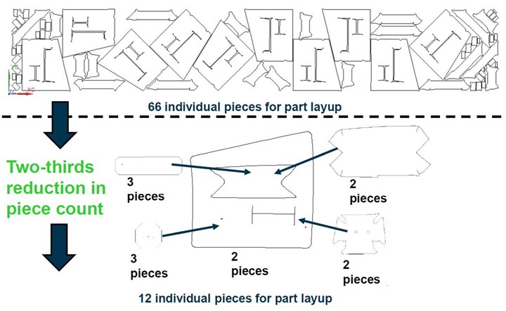
The 12 NCF preform elements for the RI-RAPM-004 challenge part reduced piece count versus the current production part made using prepreg. SOURCE | Slide 6, “Fabrication of a Complex Part …” by Tsotsis, et. al.
Resin infusion modeling
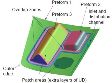
Flow analysis model for the RI-RAPM-004 challenge part. SOURCE | Fig. 7 and Slide 7, “Fabrication of a Complex Part …” by Tsotsis, et. al.
A model comprising the 12 preform elements was created for resin flowanalysis using low-pressure RTM (maximum 30 bar) to determine the optimum strategy for infusion, resin outlet positioning and flow channeling. The model assumed a fiber-volume fraction of 50% for base preform plies and 54.8% for pad-up plies.
The resin outlet was originally located in the center of the part’s bottom edge (see left image, below). Flow modeling showed that at 95% resin filling, the resin flow path was headed to the lower right corner and there was a high likelihood of forming a dry spot along the bottom right of the part. “By moving the outlet to where the resin wanted to go, the chances for creating a dry spot could be greatly reduced,” explains Boeing technical fellow and RAPM principal investigator Tom Tsotsis.
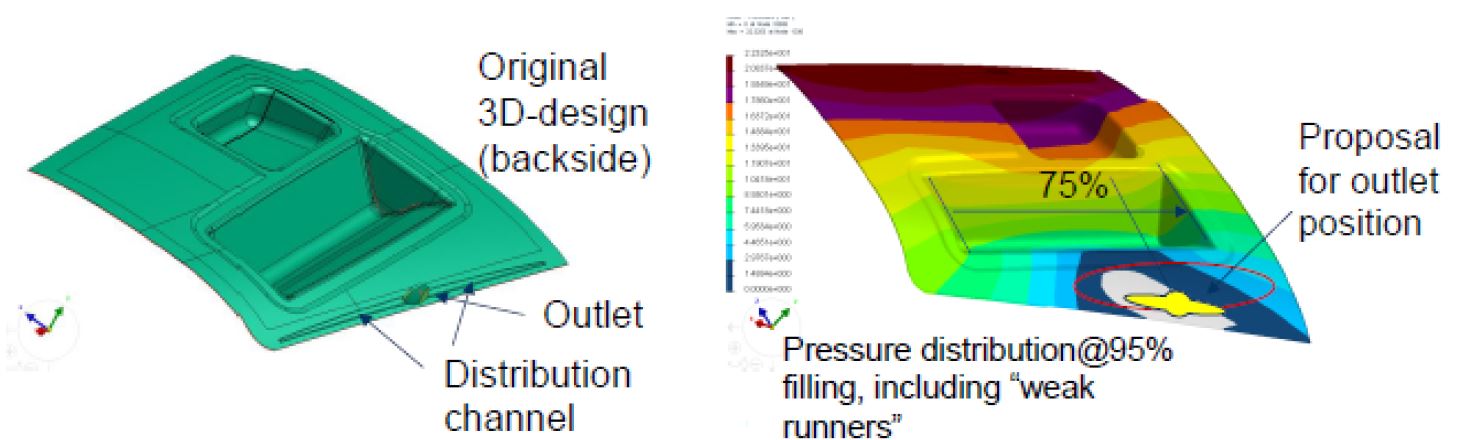
Original resin outlet location (left) resulted in a resin flow pattern (right) with a high risk for creating a dry spot at the lower right. The solution proposed was to relocate the resin outlet to the predicted dry spot (right). SOURCE | Fig. 9 and Slide 8, “Fabrication of a Complex Part …” by Tsotsis, et. al. and Slide 14, “Process Modeling to Improve Tool Design and Part Quality for Resin Infusion” by Tsotsis.
As explained in the CW May 2020 feature on RAPM, flow modeling was performed by Huntsman (Basel, Switzerland) — supplier of the FAF2 two-part epoxy resin used —with PAM RTM software (ESI Group, Paris, France). For the RI-RAPM-004 part, flow modeling showed:
- Weak runners should be used vs. strong runners to ensure uniform preform filling and reduce risk for racetracks/dry spots;
- The resin distribution channel/main feedline should be shortened (to slow resin flow);
- Racetracking was predicted to occur along the edges of the various preform elements.
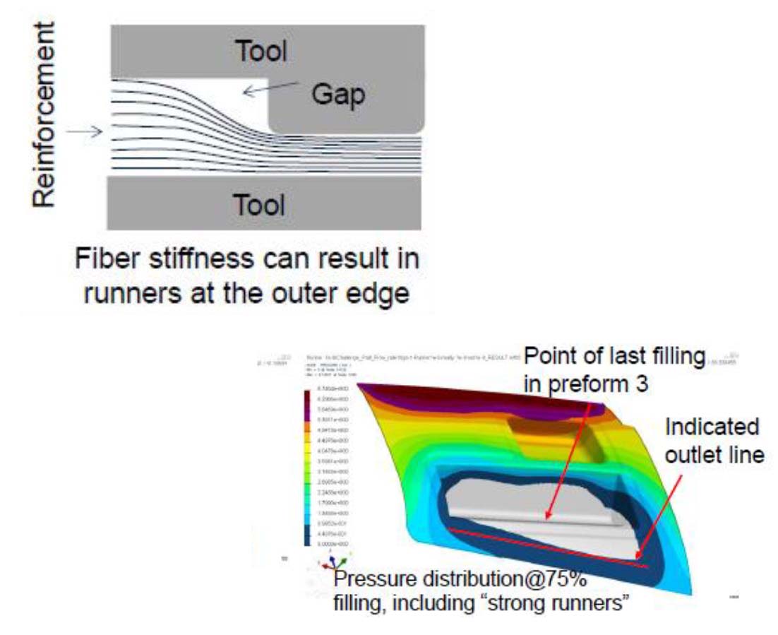
“Runners” are gaps between the preform and mold tool which allow resin to flow on top of the preform and affect racetracking during infusion. SOURCE | Slide 12, “Process Modeling to Improve Tool Design and Part Quality for Resin Infusion” by Tsotsis.
“In the Huntsman lexicon, ‘runners’ are essentially gaps between the preform and the mold edge,” explains Tsotsis. “In the context of the flow modeling for the RI-RAPM-004 part, having weak runners meant preventing racetracking.” This is because having a small gap between the preform and mold allowed resin to flow on top of the preform and then be forced down into the preform once gap infusion was completed. Having strong runners, however, would mean a large gap and would create too fast a resin flow for the complex geometry of the RI-RAPM-004 challenge part.
These results influenced both the part’s preform and tool design to make sure no dry spots occurred. With these modifications, flow modeling showed that the mold should be filled in 120 seconds with a flow rate of 10-40 grams/second at a maximum pressure of 30 bar and tool temperature of 130-150°C.
Note that initial resin infusion trials showed dry spots in the bottom of the rectangular deep-draw section, as well as fiber distortion near the resin outlet due to lifting of one of the skin preform stacks. To solve this, the resin inlet and outlet locations were reversed. Flow modeling confirmed this would work.
Slide 15, “Process Modeling to Improve Tool Design and Part Quality for Resin Infusion” by Tsotsis.
Preforming and infusion
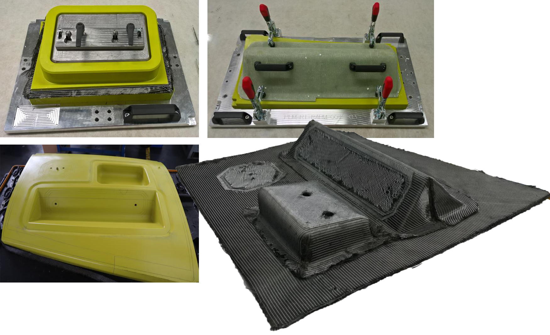
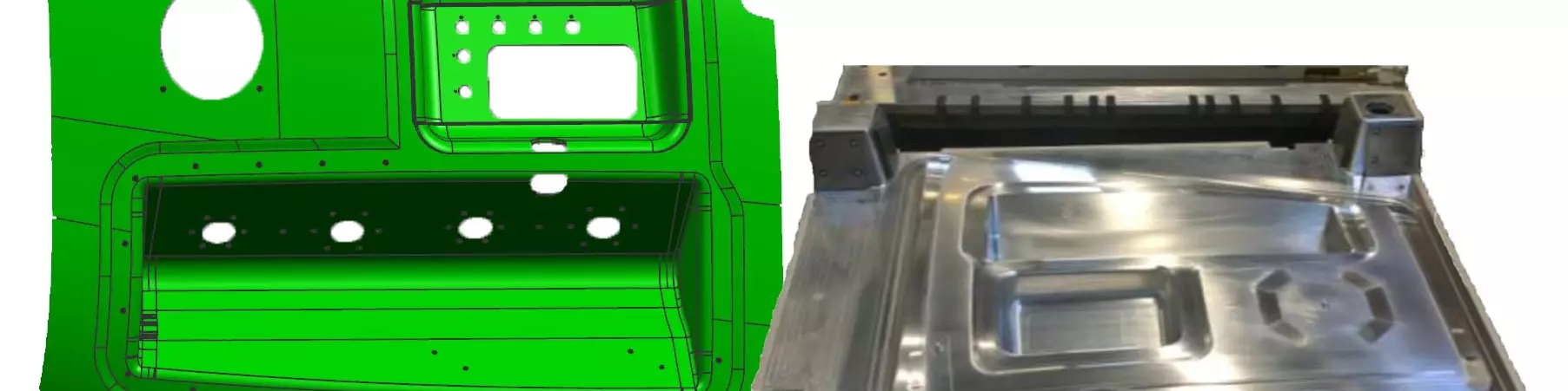
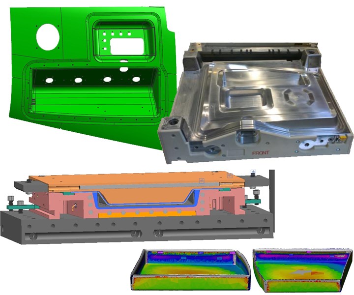
Preform tools for the rectangular and V-shaped deep-draw details (top left, right) produced the preform elements that were then assembled onto the full part preform tool (bottom left) and heat set into the final part preform (bottom right). SOURCE | Fig. 5, 11 and Slides 9, 13 from “Fabrication of a Complex Part …” by Tsotsis, et. al.
RI-RAPM-004 parts were made by SGL Composites (Ried im Innkreis, Austria). Preforms were shaped using low-cost tools made from polyurethane-based Raku-Tool from RAMPF Tooling Solutions (Grafenberg, Germany). These tools were very easy to mill and provided an extremely fine surface structure and excellent dimensional stability, with heat resistance up to 110°C, which was sufficient for heat-setting the preforms.
The rectangular and V-shaped deep-draw sections were each preformed to near-net shape by preheating and then pressing in their respective preforming tools. These details were then assembled using the full part preform tool. Though preforming was done by hand in RAPM, it could easily be automated for volume production.
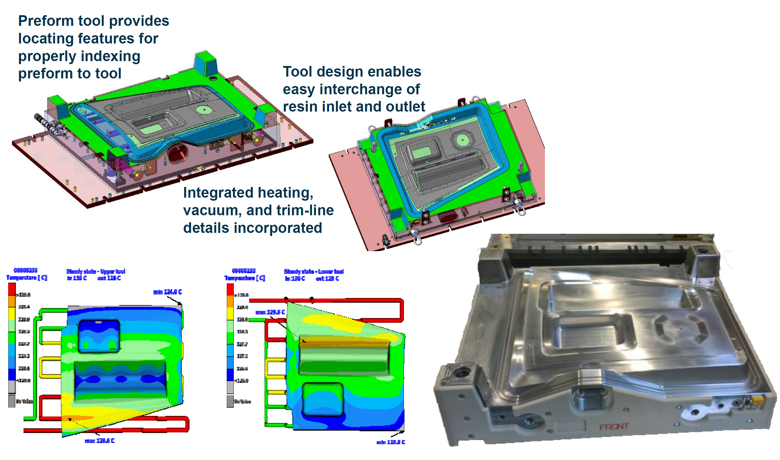
Machined polyurethane preforming tools and aluminum infusion tools (bottom right) were designed — including thermal analysis (bottom left) — to work together for low-cost, flexible processing. SOURCE | Fig. 4 and Slides 9, 11, 12, “Fabrication of a Complex Part …” by Tsotsis, et. al.
The assembled preform was then loaded into the aluminum infusion tool. The preforming and infusion tools were designed to enable a robust yet cost-effective process. Modeling of the infusion tool’s thermal performance was completed before that tool was finalized and machined. Results showed the difference between hot and cold spots was within tolerance — 5.6°C for the top tool and 4.3°C for the bottom tool.
After infusion and initial cure at 130°C, all parts were post-cured at 180°C and then machined to net shape. Once process parameters were set, 10 parts were produced and sent to Boeing for evaluation. These parts were of similar or better quality vs. prepreg-based production parts.
The parts trials in RAPM’s resin infusion track demonstrated that this approach can be used to make high-quality parts for four different preform fabrics and two different resins.
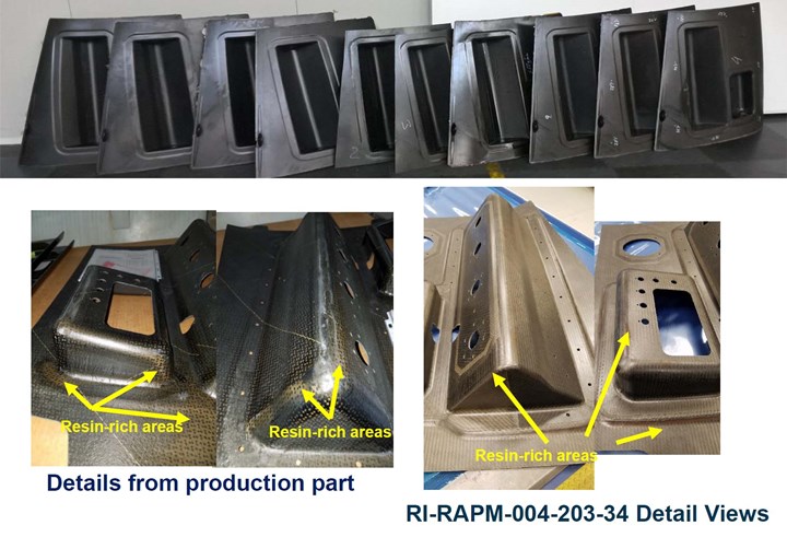
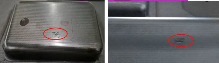
Finished RI-RAPM-004 parts made by SGL Composites showed similar or better quality vs. prepreg-based production parts and were sent to Boeing for full evaluation. SOURCE | Fig. 13 and Slides 14, 15 from “Fabrication of a Complex Part …” by Tsotsis, et. al.
Thermoset prepreg parts
Most of the details for RAPM’s thermoset prepreg parts trials are presented in the main feature article and the blog/online sidebar “Novel prepreg for compression molding in RAPM”, including discussion of the spring-frame and double diaphragm forming (DDF) processes used. This track began with the manufacturing development parts shown below.
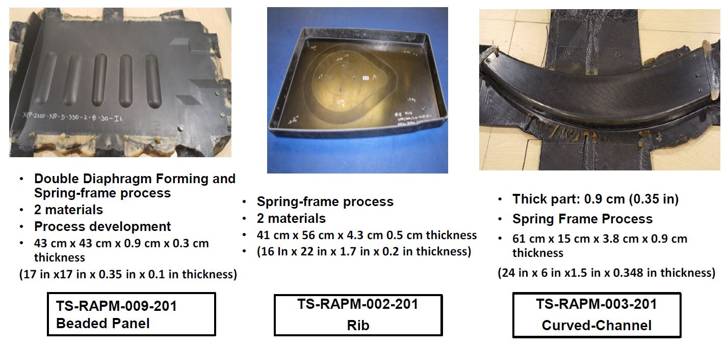
Manufacturing development parts trialed in RAPM’s thermoset prepreg forming track . SOURCE | Fig. 6 from 2019 SAMPE technical paper, “Rapid High Performance Molding (RAPM) for Small Parts” by Gail Hahn and Thomas K. Tsotsis, The Boeing Company.
However, there was one achievement in this part of RAPM that deserves more detail here. It was explained that all three parts above were made using three different epoxy prepregs based on resins from Solvay Composite Materials (Alpharetta, Ga., U.S.):
- CYCOM 5320-1 — what Gail Hahn at Boeing described as “our go-to for out of autoclave (OOA) parts”
- CYCOM 970 — a solvent vs. hot-melt prepreg option
- XEP-2750 — a new aerospace system now commercialized as EP-2750, optimized for press forming.
As explained in the blog on EP2750, one of its characteristics optimized for compression molding is its fully impregnated nature versus CYCOM 5320-1, which is optimized for edge-breathing required in vacuum bag only OOA prepreg processing. CYCOM EP2750, although only slightly higher in resin content — 40% vs. 36% for CYCOM 5320-1 — better maintains hydrostatic pressure during compaction and cure in the matched metal tool cavity of press forming, reducing the risk for dry areas, inconsistent cured part thickness, wrinkles and poor surface finish.
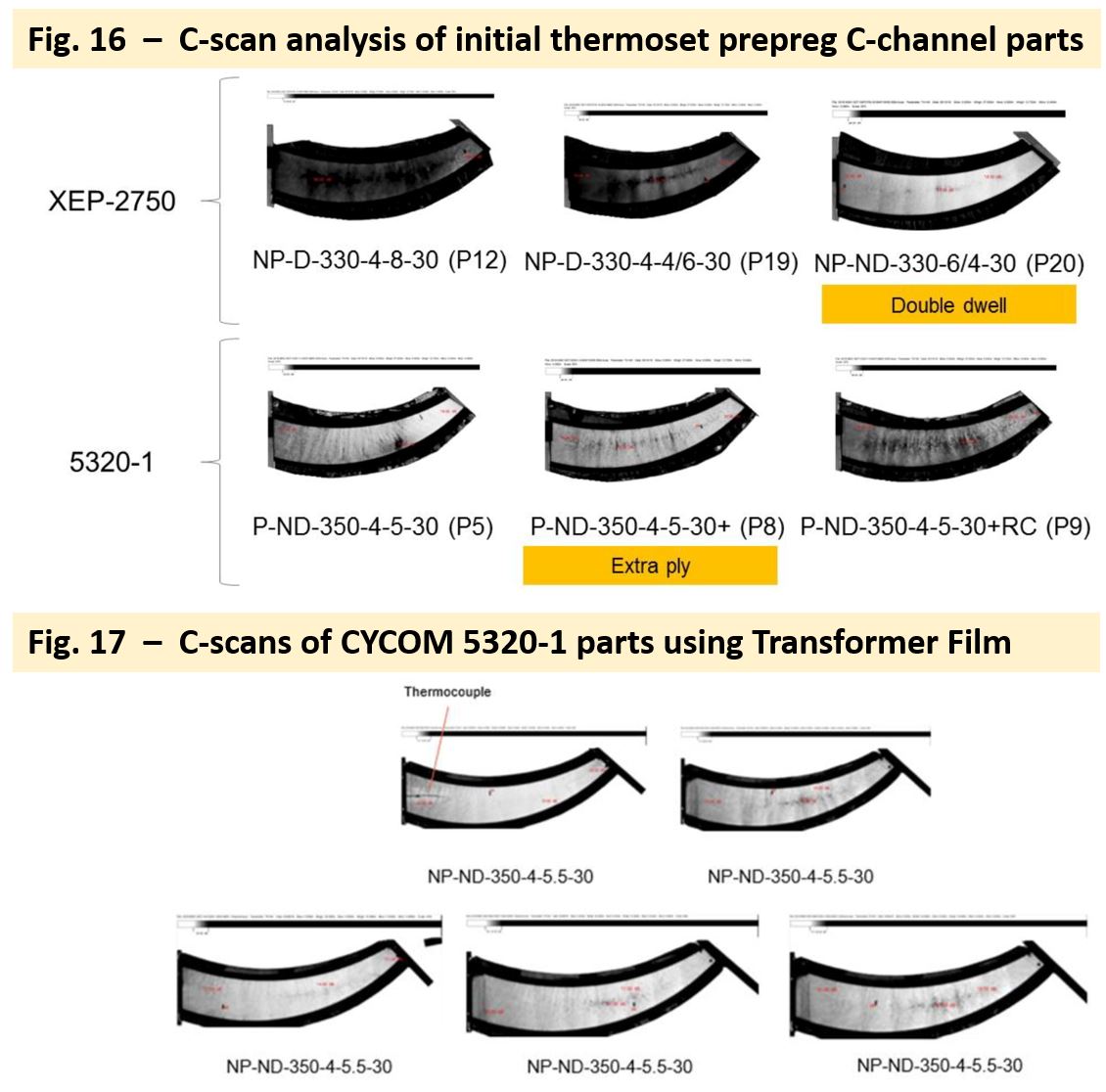
Compression molded parts using CYCOM 5320-1, even with an extra ply of prepreg showed wrinkles and porosity (Fig. 16). However, repeatable, high-quality parts were produced by adding a Transformer Film prior to compression molding (Fig. 17). SOURCE | Fig. 16 (top) and Fig. 17 (bottom), “Challenges of Aerospace Structural Part Geometries for High-Rate Compression Molding” by Aurele Bras, et. al.,
However, Solvay did develop a means for achieving the same results withCYCOM 5320-1. It is a patented Transformer Film, which is applied to the part layup prior to compression molding and increases resin content to maintain hydrostatic pressure during press forming. Initial TS-RAPM-003 curved C-channel parts made with CYCOM 5320-1 showed wrinkles, which also carried porosity. An extra ply of prepreg did reduce the magnitude of the wrinkles and porosity but did not eliminate them.
Shown in Fig. 16 and 17 from the SAMPE 2020 technical paper, “Challenges of Aerospace Structural Part Geometries for High-Rate Compression Molding” by Aurele Bras, et. al., wrinkles and porosity were eliminated by using the Transformer Film. As explained by Alejandro Rodriguez, senior applications engineer at Solvay Composite Materials, “Repeated manufacturing of C-channel parts using compression molding with CYCOM 5320-1 3K 8HS prepreg and Solvay Transformer Film show the quality and robustness of this high-rate manufacturing process.”
Thermoplastic prepreg forming
RAPM also used compression molding with thermoplastic composites. One of the first parts trialed in this track was the TP-RAPM-002 rib. It used a single-step process to mold a blank made from 12K carbon fiber reinforced polyetherketoneketone (PEKK) 12-inch wide unidirectional (UD) tape into a final-shaped part.
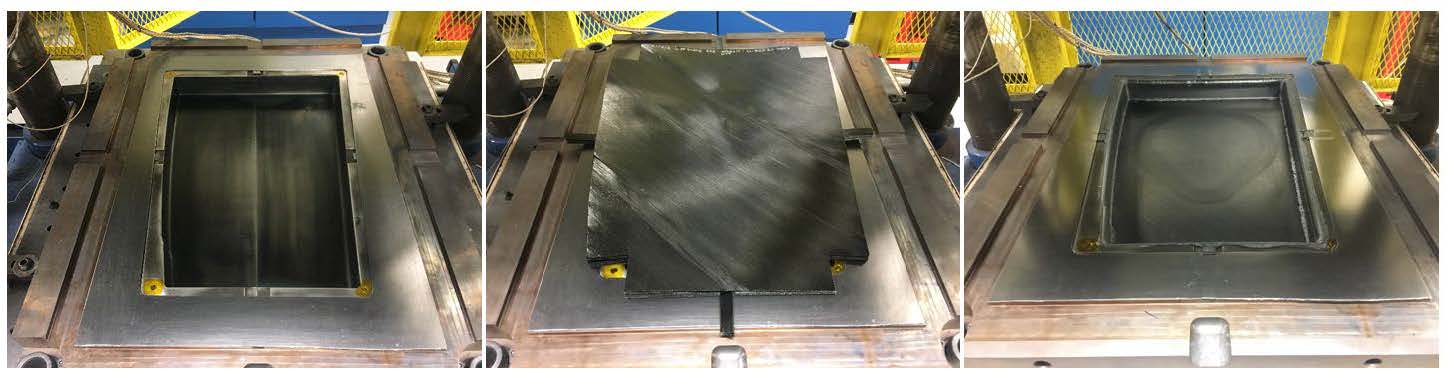
Molding of a TP-RAPM-002 rib from UD tape blank to finished part in a single-step process. SOURCE | Fig. 8, “Rapid High Performance Molding of Structural Thermoplastic Composite Parts” by Schell, et. al.
The tooling approach developed used a thin aluminum bladder that was pressurized with inert gas at high temperatures, expanding to apply even pressure to all of the part’s surfaces during stamping. This made it possible to maintain hydrostatic pressure horizontally against the part’s vertical flanges while using a press that lacked horizontal hydraulic system and controls and thus acted only in the vertical direction.
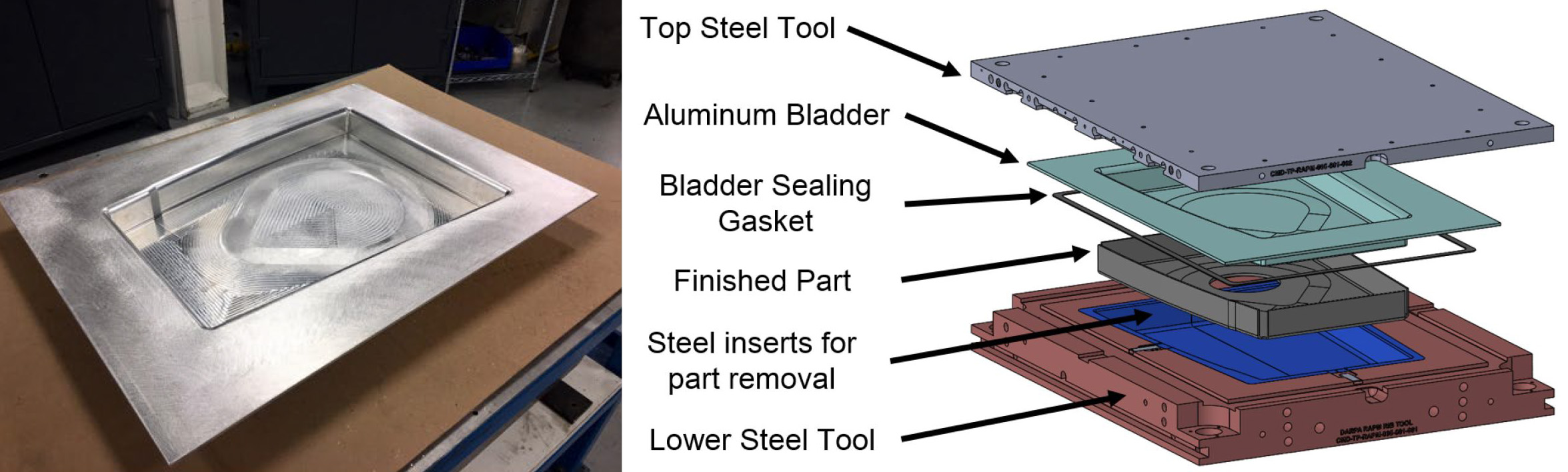
Aluminum bladder and tool assembly used to mold TP-RAPM-002 rib parts. SOURCE | Fig. 5, 6 from “Rapid High Performance Molding of Structural Thermoplastic Composite Parts” by Schell, et. al.
SOURCE | Fig. 7, “Rapid High Performance Molding of Structural Thermoplastic Composite Parts” by Schell, et. al.
The aluminum bladder was milled from a single billet of 2024 aluminum and was undersized 30% from the final part thickness to accommodate the bulk of the thermoplastic unidirectional tape in the un-consolidated blank. Although the same bladder approach was used to consolidate the thermoplastic fabric prepreg blank for the TP-RAPM-003 curved C-channel, that bladder was made from magnesium and required super plastic forming. The aluminum bladder for the -002 ribs did not require super plastic forming.
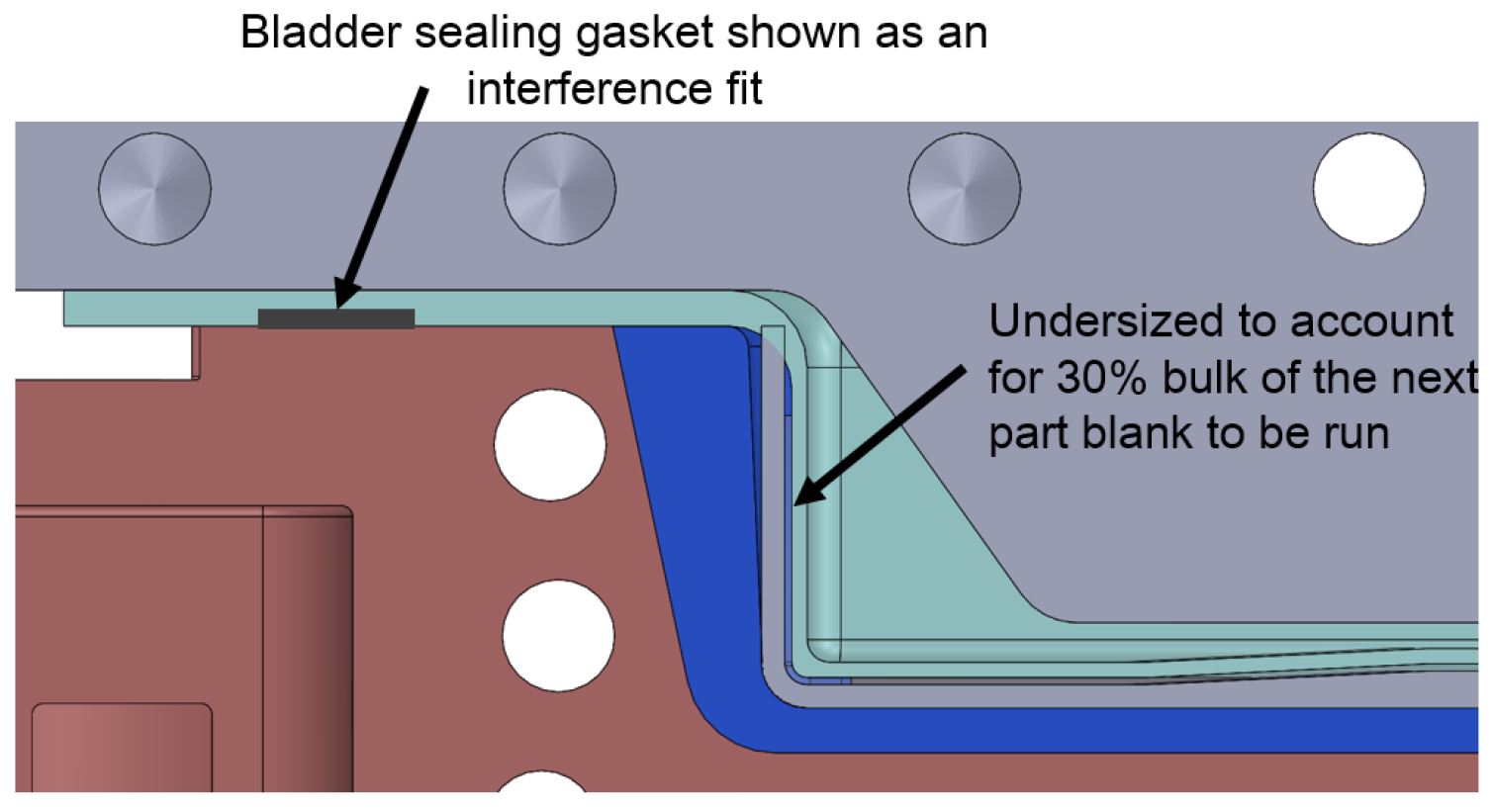
Just below the bladder is a high-temperature graphite sealing gasket that runs spans the full perimeter of the bladder. This tooling setup functioned so that the press hydraulics bottomed out on this gasket and would then apply a force through the gasket. This force then sealed the argon gas within the aluminum bladder. The press hydraulics did not apply pressure to the material laminate itself — the pressure was applied by the gas-filled bladder. In order to pressurize the bladder a pressure inlet was added to the top steel tool. This allowed argon gas to be supplied from a cylinder and pressurize the bladder cavity while the press hydraulics sealed the bladder and kept the tool closed.

SOURCE | Fig. 3, “Rapid High Performance Molding of Structural Thermoplastic Composite Parts” by Schell, et. al.
The top and bottom steel tools were 410 stainless as were the removable inserts in the lower tool to facilitate part removal. When the press cycle started, the upper tool with the aluminum bladder lowered to slowly press the bulk layup into the female cavity of the lower tool. This is where the additional 30% bulk factor in the aluminum bladder at room temperature was key to fitting the bulk layup into the tool without interference. The pressure applied by the bladder to the thermoplastic material was critical to achieve proper consolidation while it experienced a volume change and shrinking due to its coefficient of thermal expansion (CTE). That shrinking was overcome by the pressure the bladder applied normal to the horizontal and vertical surfaces of the part.
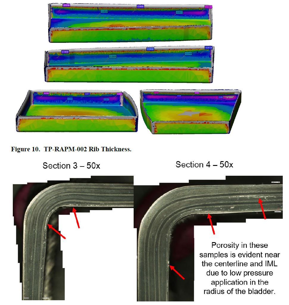
Thickness variation and porosity in TP-RAPM-002 rib parts. SOURCE | Fig. 10 and 11, “Rapid High Performance Molding of Structural Thermoplastic Composite Parts” by Schell, et. al.
The parts produced using this method, however, showed both porosity and variations in cured part thickness. The bladder used with a vertical-only press (motion in only one axis) was very difficult to control. The forming experiments were successful in proving that a thin aluminum bladder can apply enough sustained pressure to consolidate a PEKK thermoplastic composite part with passable NDI results. However, the approach requires more analysis to be successful for this type of complex-geometry rib, which featured pad-ups in the center of the web as well as vertical flanges on all four sides.
The magnesium bladder tool used to consolidate the thermoplastic fabric prepreg blank for the TP-RAPM-003 curved C-channel was more successful. This process was completed using the Boeing St. Louis PtFS work cell, and is described in the online sidebar, “RAPM development of PtFS”. The consolidated blanks were then stamp formed by ATC Manufacturing to the final part shape. Those two processes used together overcame the limitations faced on the TP-RAPM-002 rib parts and showed that complex geometries are attainable with stamp forming for complex-shaped composite parts for which standard, one-step compression molding might not be possible.


Related Content

Industrial composite autoclaves feature advanced control, turnkey options
CAMX 2024: Designed and built with safety and durability in mind, Akarmark delivers complete curing autoclave systems for a variety of applications.
Read More
Plant tour: Airbus, Illescas, Spain
Airbus’ Illescas facility, featuring highly automated composites processes for the A350 lower wing cover and one-piece Section 19 fuselage barrels, works toward production ramp-ups and next-generation aircraft.
Read More
Uavos, Mira Composites perform test flight of ApusNeo HAPS aircraft
The highly composite 18-meter-wingspan platform successfully obtained imagery from 3,000-12,000-meter altitudes, supporting its progress toward use in high-altitude missions.
Read More
Industrial curing autoclaves with advanced control systems
CAMX 2025: Turnkey Akarmak autoclaves support various composite curing needs with enhanced process control, international specification compliance and optimal heat distribution.
Read MoreRead Next

Next-gen fan blades: Hybrid twin RTM, printed sensors, laser shock disassembly
MORPHO project demonstrates blade with 20% faster RTM cure cycle, uses AI-based monitoring for improved maintenance/life cycle management and proves laser shock disassembly for recycling.
Read More
Cutting 100 pounds, certification time for the X-59 nose cone
Swift Engineering used HyperX software to remove 100 pounds from 38-foot graphite/epoxy cored nose cone for X-59 supersonic aircraft.
Read More
Ultrasonic welding for in-space manufacturing of CFRTP
Agile Ultrasonics and NASA trial robotic-compatible carbon fiber-reinforced thermoplastic ultrasonic welding technology for space structures.
Read More