
Novel prepreg for compression molding in RAPM
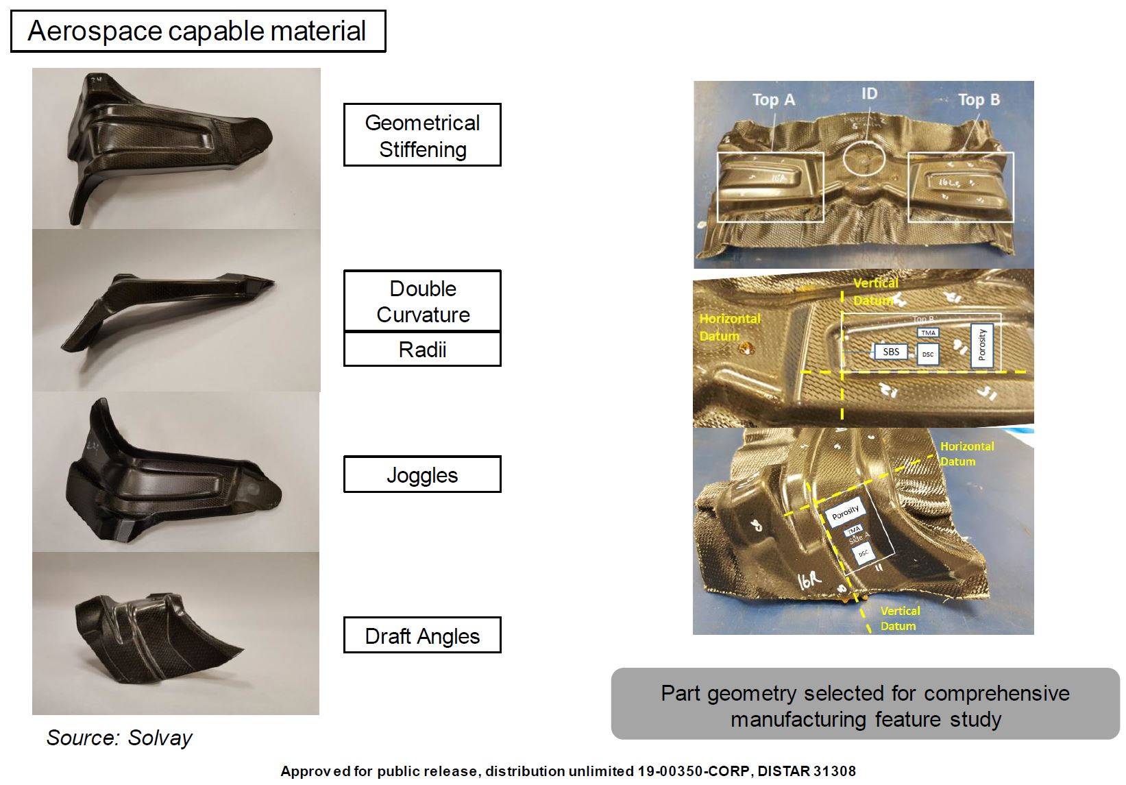
Solvay and Boeing combine aerospace performance with process knowledge for high-rate, low-cost composites production.


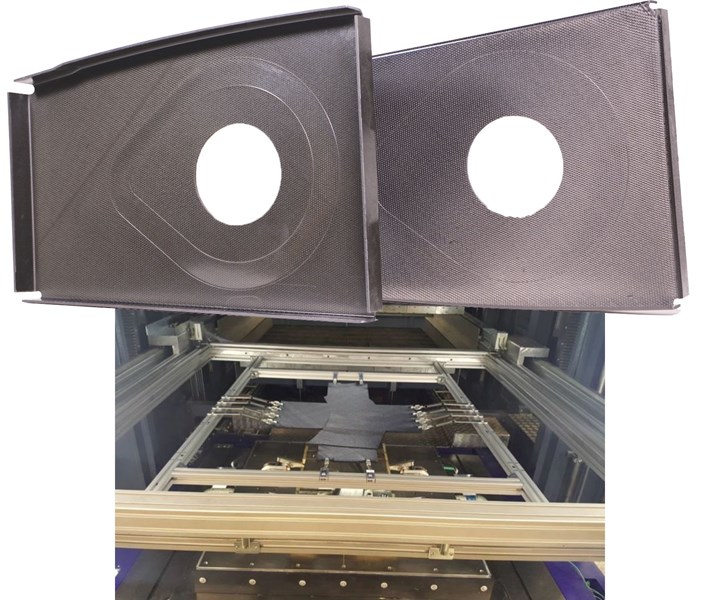
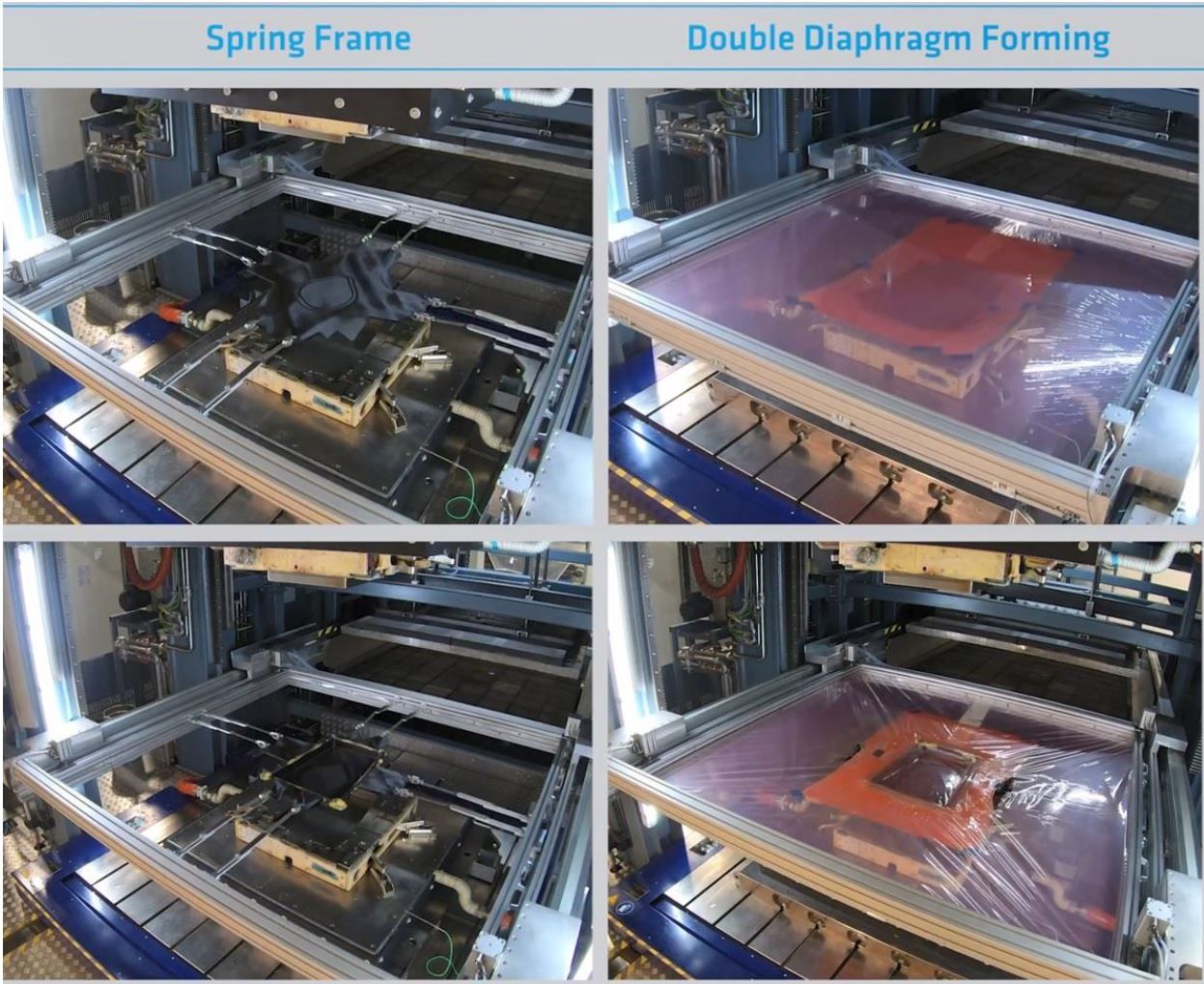
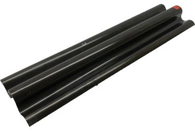
Rib parts (top) trialed using spring-frame molding (shown here, bottom, with curved C-channel part) and double diaphragm forming (DDF) processes in the DARPA-funded and Boeing co-funded RAPM program which is administered as a cooperative agreement through the Army Research Office. SOURCE | Boeing, DARPA, Solvay.
Carbon fiber/epoxy prepreg has been the baseline material for aerospace composites for decades because it provides high mechanical properties and precise resin/fiber content, as well as ease of handling for layup and autoclave cure. However, as aircraft and urban air mobility (UAM) manufacturers explore higher production rates and lower costs, compression molding is attractive, cutting cycle times and boosting efficiency versus the autoclave. At its simplest, compression molding comprises preheating the molding material, placing it into an open tool cavity and consolidating with hydraulic pressure at temperature, during which the liquid thermoset material is converted to a solid. The cured part is then ejected for any required trimming and finishing steps.


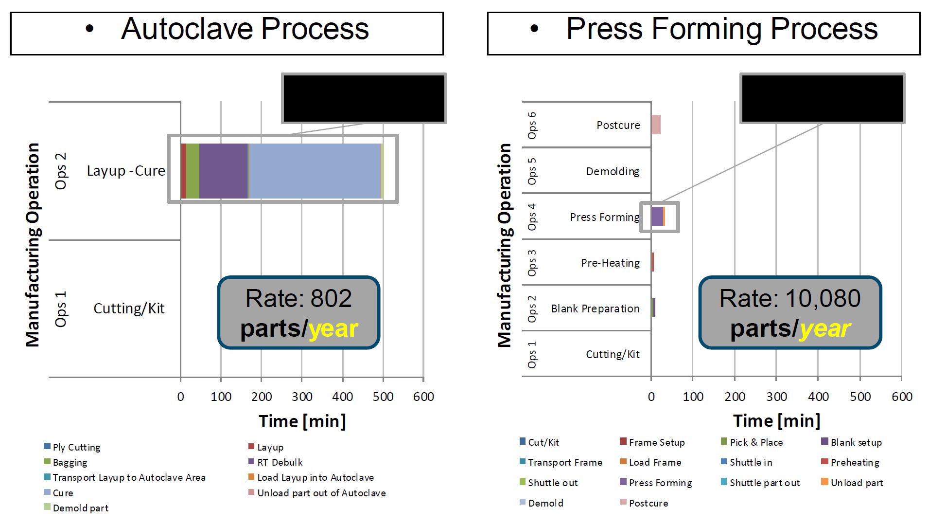
SOURCE | Boeing, DARPA, Solvay. Slide 8 “Rapid High Performance Molding of Structural xEP-2750 Prepreg for Compression Molding” by Timothy J. Luchini, et. al., SAMPE 2019.
Combining press molding and prepreg not only delivers an efficient, high-rate process with the performance and easy handling of prepreg, it also avoids some of the complex process dynamics of filling dry reinforcements with liquid resin during processes such as resin infusion and resin transfer molding (RTM). For smaller aerostructures especially, prepreg press molding offers the potential for takt times of <30 minutes while still achieving high-quality, complex geometry parts.
Solvay Composite Materials (Alpharetta, Ga., U.S.) was a key partner in the RApid high-Performance Manufacturing (RAPM) program led by The Boeing Co. (Chicago, Ill., U.S.). RAPM is the “forming” part of The Tailorable Feedstock and Forming (TFF) program launched by the Defense Advanced Research Projects Agency (DARPA, Arlington, Va., U.S.) in 2015. Its goal is to enable rapid, low-cost and agile manufacturing of small, complex-shaped composite parts and increase composites’ ability to compete against machined aluminum in defense applications.
SOURCE | Boeing, DARPA, Solvay. Slide 7 “Rapid High Performance Molding of Structural xEP-2750 Prepreg for Compression Molding” by Timothy J. Luchini, et. al., SAMPE 2019.
A long-time supplier to Boeing for defense applications, Solvay has also been a leader in novel solutions for commercial aerospace, such as the out-of-autoclave (OOA) epoxy prepreg CYCOM 5320-1, and for automotive as well, such as the 1-minute takt time, vinyl hybrid SolvaLite 730 prepreg.
RAPM was a perfect opportunity for Solvay to test and refine its experimental system XEP-2750, now commercialized as CYCOM EP2750, which was developed to bridge aerospace and automotive composites production. This blog — an online sidebar to the May 2020 feature “Revolutionizing the composites cost paradigm, Part 2: Forming” — reviews that development as well as the compression molding processes used and what CYCOM EP2750 offers to both aerospace and automotive composites manufacturers.
References for this blog include:
- “Spring Frame Press Fabrication of Aerospace Production Components” by Timothy J. Luchini1, Alejandro J. Rodriguez2, Scott A. Rogers2, Aurele Bras3, Adam Whysall3, Richard Russell3, Scott Lucas2, Gail L. Hahn1. SAMPE Conference Proceedings. Charlotte, NC, May 20-23, 2019.
- “Challenges of Aerospace Structural Part Geometries for High-Rate Compression Molding” by Aurele Bras1, Alejandro J. Rodriguez2, Richard Russell1, Timothy J. Luchini3, Travis Adams3, Adam Whysall1, Scott A. Rogers2, Scott Lucas2, Gail L. Hahn3. Society for the Advancement of Material and Process Engineering – North America.SAMPE Conference Proceedings. Seattle, WA, May 4-7, 2020. Society for the Advancement of Material and Process Engineering – North America.
- “Rapid High Performance Molding of Structural xEP-2750 Prepreg for Compression Molding” by Timothy J. Luchini1, Alejandro J. Rodriguez2, Scott A. Rogers2, Aurele Bras2, Adam Whysall2, Richard Russell2, Scott Lucas2, Gail L. Hahn1. SAMPE 2019.
1The Boeing Company, Saint Louis, MO 63134, 2Solvay Composite Materials, Anaheim, Calif., U.S. and 3Solvay Composite Materials, Heanor, U.K.
- CompositesWorld webinar: “Automotive Processes for High-rate Aerospace Composites Manufacturing” by Alejandro Rodriguez, Solvay Composite Materials, Anaheim, Calif., U.S.
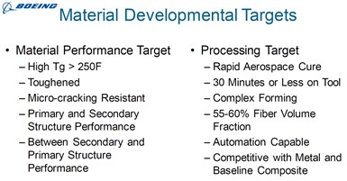
Material and process targets
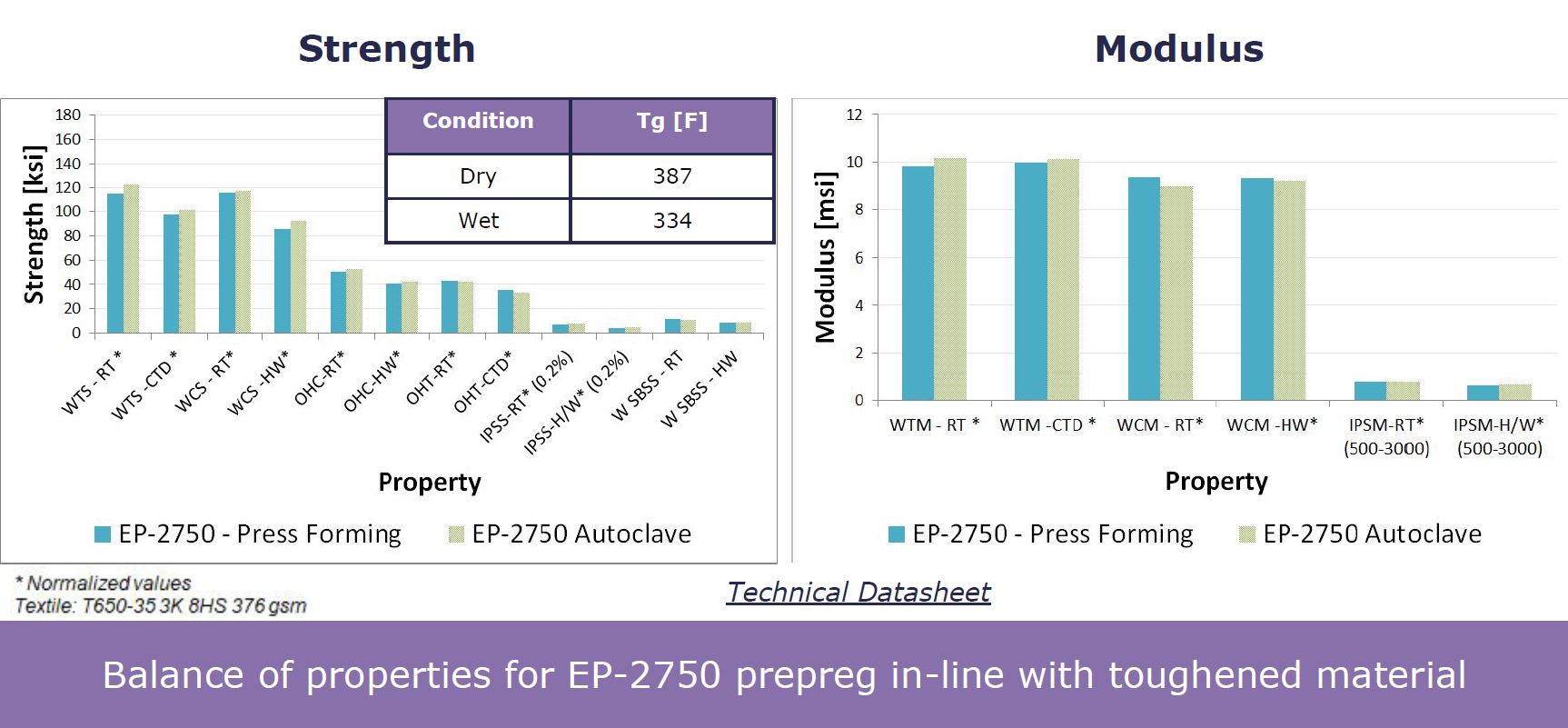
WTS, WCS – wet tensile and wet compression strength
RT – room temperature
CTD, HW – cold temperature dry, hot wet
IPSS, IPSM – interply (interlaminar) shear strength and shear modulus
SOURCE | webinar presented by SolvayCW (April, 2020)
SOURCE | Slide 5, “Rapid High Performance Molding of Structural xEP-2750 Prepreg for Compression Molding” by Timothy J. Luchini, et. al., SAMPE 2019.
CYCOM EP2750 was developed to meet the performance targets set by Boeing for an aerospace toughened epoxy, exhibiting a balance of glass transition temperature (Tg) up to 350°F, good notched properties — e.g., open hole compression (OHC) and open hole tension (OHT) — and solvent resistance. This new class of prepreg is applicable to both primary and secondary aerostructures and is compatible with multiple reinforcements (e.g., carbon and glass fiber).
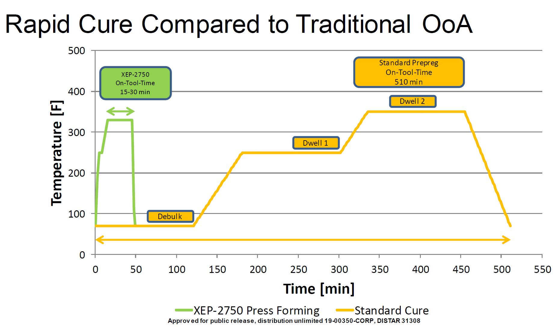
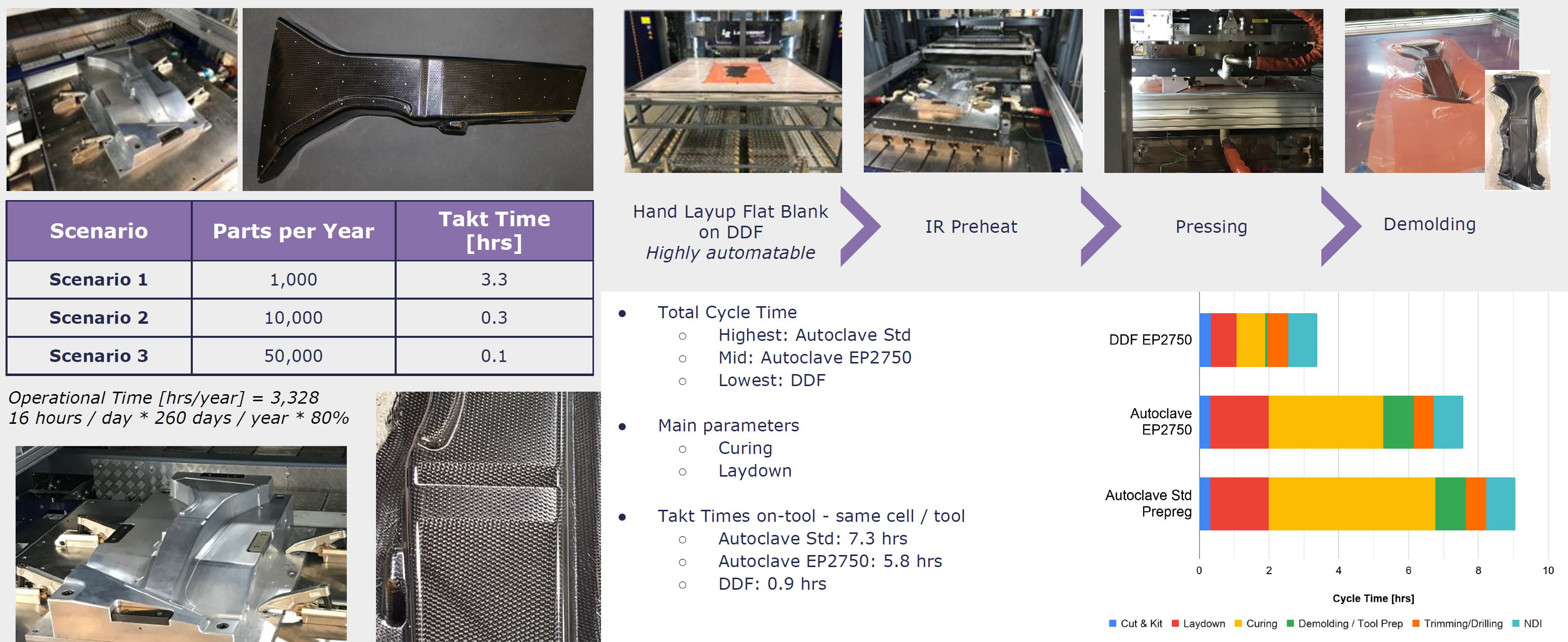
CYCOM EP2750 was also developed with the ability to scale up production using automated handling and compression molding. This includes an on-tool cure time of 15-30 minutes at 330-370°F, with a 1-hour post-cure at 350°F. This takt time of 30 minutes or less enables an annual production volume of 10,000 parts per tool.
Solvay used two variations of compression molding during the RAPM program: spring-frame molding and double diaphragm forming (DDF). Both use the principle of holding a flat blank and carrying it through an infrared (IR) preheat stage before shuttling it into a matched metal tool cavity. The press then closes the steel mold following an automated program and applies full pressure to the prepreg for the remaining time on-tool.
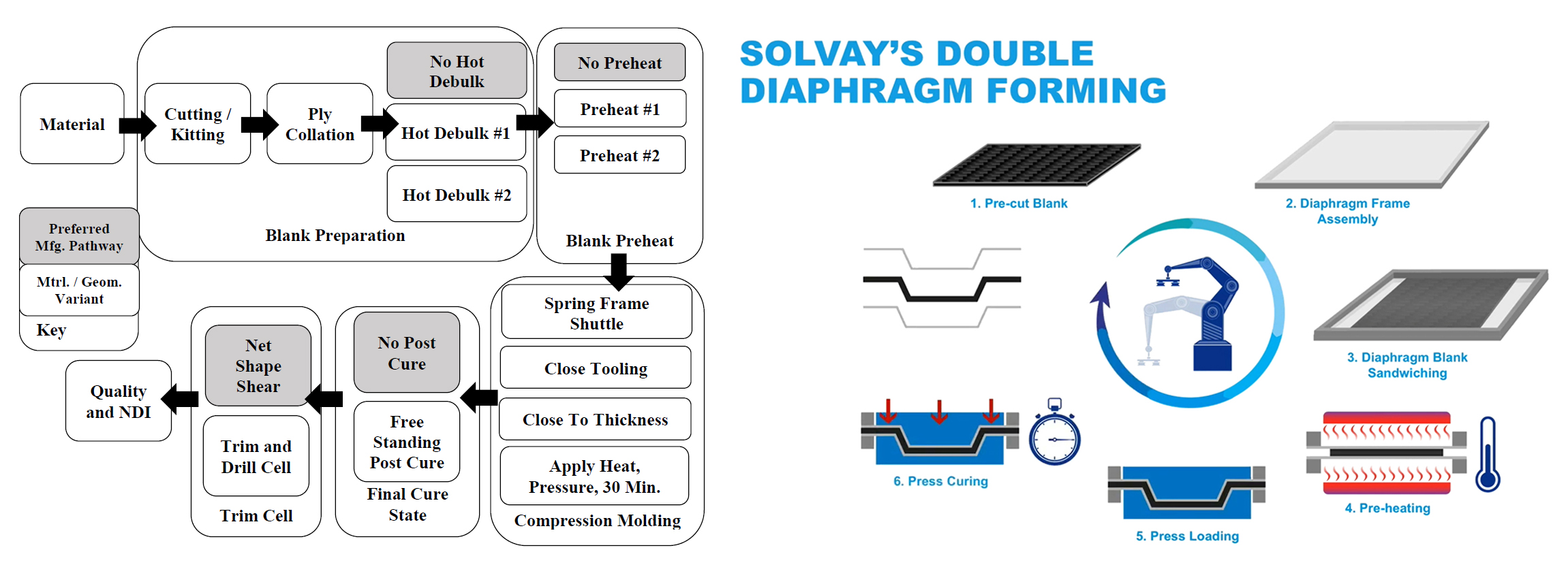
Process diagrams for spring-frame molding (left) and DDF. SOURCE | Boeing, DARPA, Solvay.
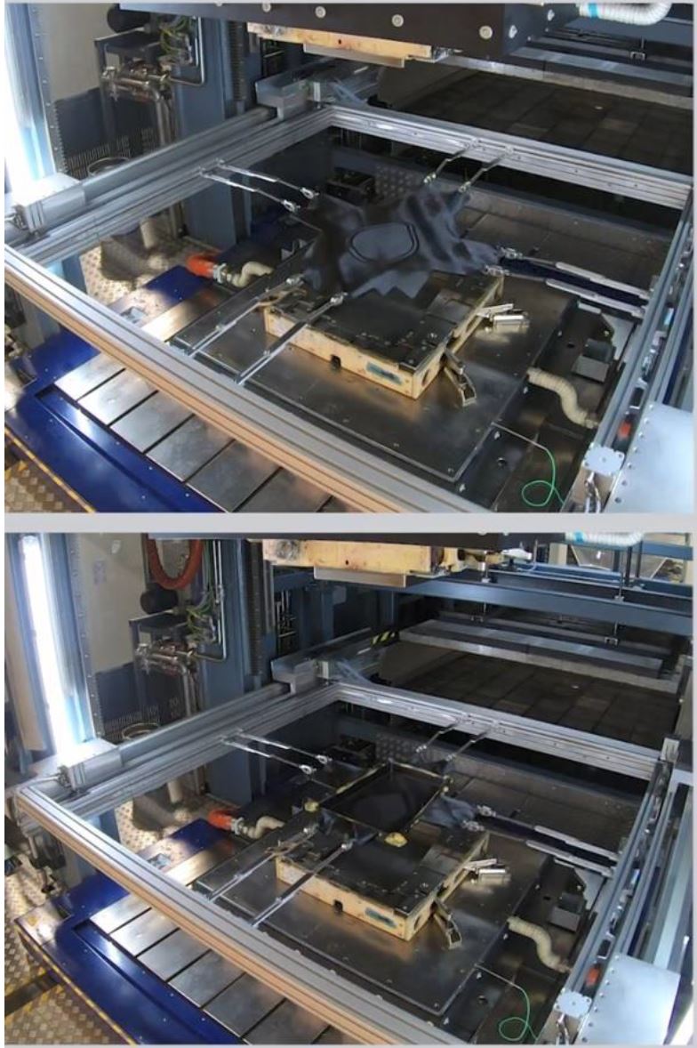
Blank shuttled from preheat to tool before closing (top) and part being released (bottom). SOURCE | Fig. 10, “Challenges of Aerospace Structural Part Geometries for High-Rate Compression Molding” by Aurele Bras, et. al., SAMPE 2020.
Both spring-frame molding and DDF use matched metal tools and offer a hot-in, hot-out approach, eliminating tool heat up and cool down, for high-rate production. Both were used to successfully mold multiple types of complex geometry parts with pad-ups, vertical flanges and thicknesses variations from 3.8 to 8.9 millimeters. These parts were made at Solvay’s Application Center in Heanor, U.K. Though not available during RAPM, Heanor now features a fully automated compression molding line from prepreg roll to molded part, achieving takt times of 15 to 60 minutes for aerospace parts made with EP2750 and takt times of 3 minutes or less for small to medium parts using automotive prepregs. Solvay sees multiple benefits in the DDF process including:
- Elimination of preforming step – 2D blank to 3D part
- No mold release or cleaning required
- Reduction in ancillary materials (e.g., breather, bleeder, bagging, tape) vs. autoclave
- Improved buy-to-fly vs. spring frame molding because less excess material is needed for attaching spring clamps.
Full vs. partial impregnation maintains pressure
Characteristics of EP2750 that facilitate compression molding include its low tack for automated pick and place handling and its fully impregnated nature versus CYCOM 5320-1, which is partially impregnated to facilitate edge-breathing, necessary for void-free laminates using OOA processing. Compression molding, however, exploits very rapid, forced resin flow due to the higher pressures applied — e.g., up to 350 psi (typical maximum for EP2750) compared to 35 psi common in autoclave processing and 14.7 psi in vacuum-only OOA processing.
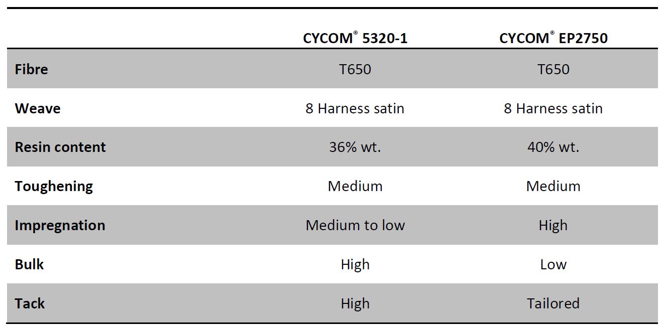
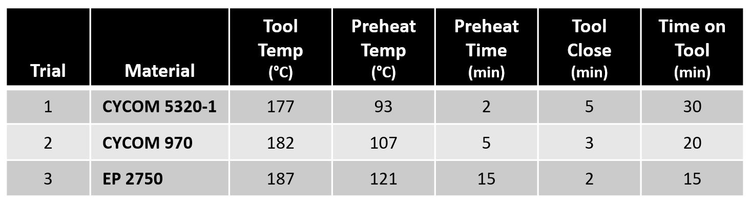
Comparison between CYCOM 5320-1 OOA prepreg and CYCOM EP2750 prepreg for compression molding. SOURCE | Table 1,
Having a more fully impregnated prepreg, even though resin content is only slightly higher — 40% in CYCOM EP2750 compared to 36% in CYCOM 5320-1 — maintains hydrostatic pressure during compaction and cure in the matched metal tool cavity, resulting in less risk for dry areas, inconsistent cured part thickness (CPT), wrinkling and other defects while ensuring good surface quality.
Notably, Solvay developed a patented Transformer Film for increasing hydrostatic pressure when using lower resin content CYCOM 5320-1 prepreg. Applied to the part layup prior to compression molding, the Transformer Film increases resin content and helped to bring the CPT up to requirements in RAPM part molding trials.
RAPM parts molding trials
As explained in CW’s May 2020 feature article, CYCOM EP2750 was one of the primary materials trialed in RAPM’s thermoset prepreg track. Pathfinder parts trialed in the initial Manufacturing & Development phase included
TS-RAPM-001 and -009 beaded access panels, TS-RAPM-002 rib and TS-RAPM-003 curved C-channel. The parts were designed at Boeing (multiple locations globally), tooling was made at C-Con GmbH (Munich, Germany), parts were manufactured at Solvay’s Applications Centre in Heanor, U.K. and were then tested at Solvay Anaheim, Calif., U.S. and Boeing St. Louis, Mo., U.S.
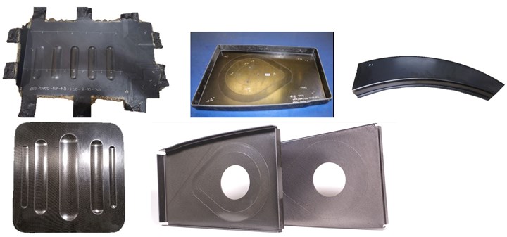
TS-RAPM-001 (bottom) and -009 (top) beaded access panels, TS-RAPM-002 ribs (center) and TS-RAPM-003 curved C-channel (right) parts. SOURCE | Boeing, DARPA, Solvay.
Cross-sections of TS-RAPM-009 parts made with EP 2750 prepreg. SOURCE | Fig. 3.2, “Spring Frame Press Fabrication of Aerospace Production Components” by Timothy J. Luchini, et. al., SAMPE 2019.
Example test matrix variables for spring-frame forming part trials. Table 2, “Spring Frame Press Fabrication of Aerospace Production Components” by Timothy J. Luchini, et. al., SAMPE 2019, edited by CW.
Surface quality was evaluated using non-destructive inspection (NDI) and selected panels were cross-sectioned for porosity, short beam shear, fiber volume fraction, resin content, degree of cure, and glass transition temperature.
Porosity levels below 0.5% were readily achieved, attributed to the high consolidation pressures of compression molding. Though process parameters had to optimized for each different part, once locked down, the process was shown to be repeatable.
TS-RAPM-009 beaded panel
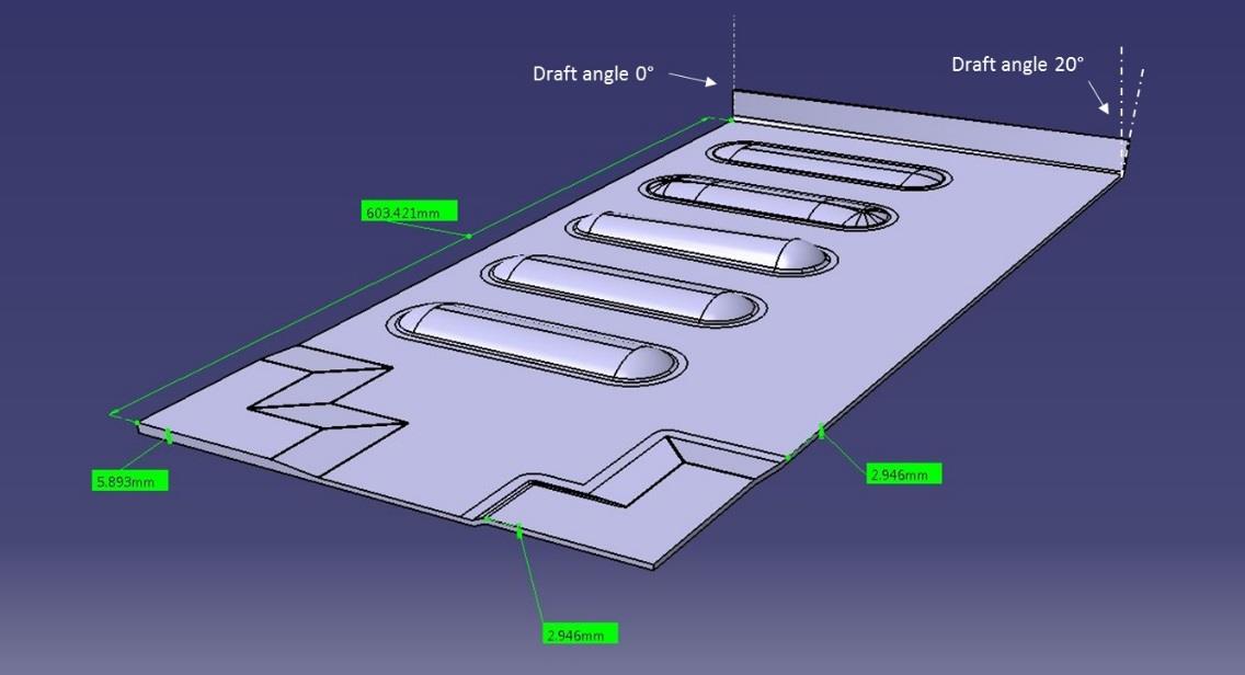
TS-RAPM-009 beaded panel geometry. SOURCE | Fig. 2, “Challenges of Aerospace Structural Part Geometries for High-Rate Compression Molding” by Aurele Bras, et. al., SAMPE 2020.
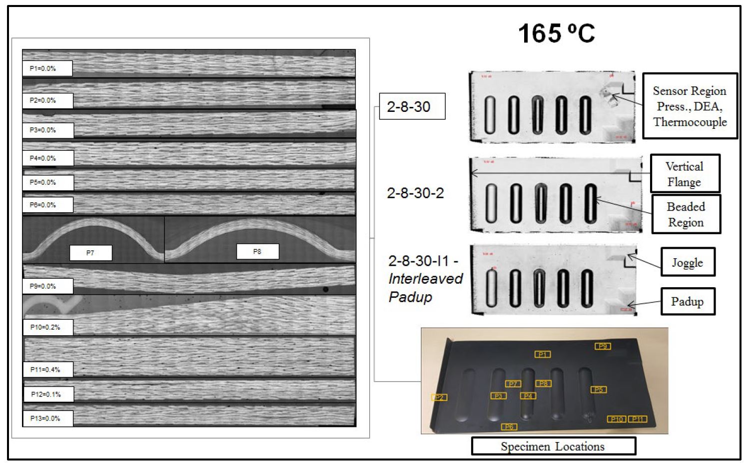
This 600-millimeter-long flat part featured parallel beads of various geometries. Thickness increased from 3 to 6 millimeters in one corner (pad-up) while the opposite corner featured a constant thickness joggle. The opposite edge comprised a vertical flange with a draft angle that varied linearly from 0° to 20°.
Slippage of pad-ups
Initial trials were run with pad-ups stacked on the surface of the layup. However, because the pad-up plies were located near the edge of the part, it was possible for them to be squeezed out of the part, resulting in a region of low pressure during cure and porosity. The solution was to interleave the pad-up plies within the laminate stack. The risk of slippage and porosity was not seen in later parts where pad-ups were located away from edges and effectively locked in by surrounding material.
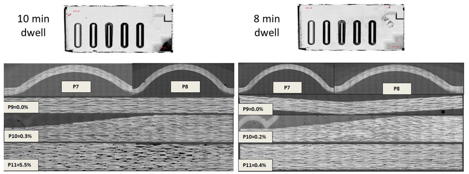
Photo-microcopy comparison of TS-RAPM-009 beaded panel part sections extracted from the thin, tapered, thick and beaded areas. SOURCE | Fig. 6, “Challenges of Aerospace Structural Part Geometries for High-Rate Compression Molding” by Aurele Bras, et. al., SAMPE 2020.
Porosity with dwell time
Increased porosity was also seen if the dwell time was too long. Beaded panels made using 8 minutes dwell had lower void content than those made with 10 minutes dwell. This was particularly true in the pad-up area, where void content was 5.5% for the 10-minute dwell and 0.4% for the 8-minute dwell. The shorter dwell maintains a high resin flow, wetting out fibers effectively and sustaining pressure in the tool cavity through cure.
The longer dwell allowed resin flow and pressure to decrease, especially in the pad-up area, due to its proximity to the edge of the tool cavity, which had no shear edge or reduction in section. Thus, the pressure in the tool cavity decreased at the part edge, especially in thicker regions where the cross-section was larger. The absence of pressure here also exacerbated the risk for slippage of the pad-up plies. “When designing tooling, a reduction in section in the surrounding of the tool cavity will help build and maintain pressure, particularly for parts with varying thicknesses,” explains Gail Hahn, Boeing research fellow and principal investigator for the RAPM project. “You need to present some form of pinching or sealing in order to encourage a state of hydrostatic pressure in the cavity.”
TS-RAPM-002 rib
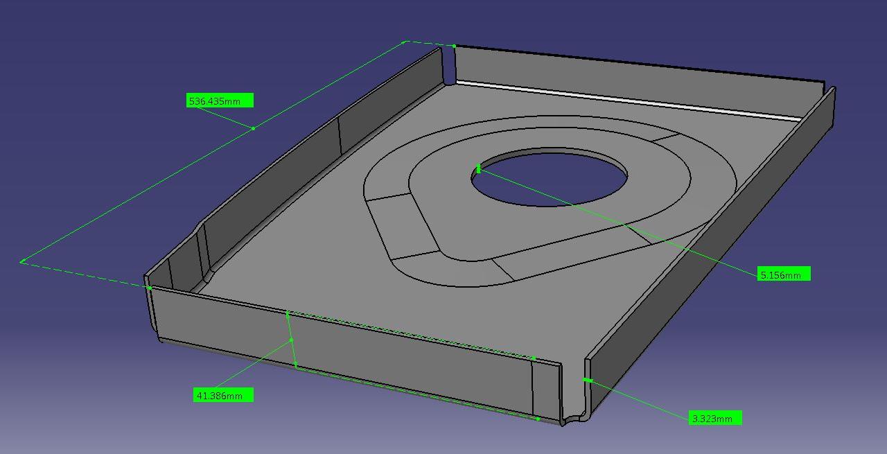
TS-RAPM-002 rib part geometry. SOURCE | Fig. 9, “Challenges of Aerospace Structural Part Geometries for High-Rate Compression Molding” by Aurele Bras, et. al., SAMPE 2020.
Once processing parameters were established for the TS-RAPM-009 beaded panels, the process was repeated for the TS-RAPM-002 rib, which measured 540 millimeters on its longest edge. The rib built up thickness in the center from 3.3 to 5.2 millimeters and the depth of the draw was 42 millimeters on the final trimmed part. All four edges featured vertical flanges. Note that a spring-in compensation angle was determined during the beaded panel trials and was then applied to the rib’s tool geometry. Beaded panel trials also led to higher tension capability and spring location modularity on the spring-frame.
Close up of TS-RAPM-002 rib in spring frame before and after molding. SOURCE | Fig. 10, “Challenges of Aerospace Structural Part Geometries for High-Rate Compression Molding” by Aurele Bras, et. al., SAMPE 2020.
Excess material for clamps
Ribs were made using both spring-frame molding and DDF. Due to the rib’s deep draw, excess material was required in order to attach the spring-frame clamps, but this could be reduced when using DDF. Another issue was that the tool design limited room for the spring clamps to be in close vicinity within the tool cavity.
Variations in CPT
The cured ply thickness (CPT) was higher on the flat parts of the rib than on its vertical edges. It was reasoned that the part’s geometry kept resin within the central flat area, noting that the vertical flanges acted as a resin seal. This helped compaction and part finish in the central flat area. However, the vertical flanges suffered from strong shear during tool closing, which caused surface roughness but not porosity (see porosity data below). CYCOM EP2750, a lower bulk material, helped to mitigate this effect — its lower thickness lessened the shear.
Variations in web thickness with prepreg resin content
Quality investigations showed repeatable ribs with porosity <0.1% and minimal fiber wrinkling/waviness. However, while it was assumed part thickness variation would be minimized with matched mold processing, review of material processing parameters and finished part CPT showed that while the tooling gap in the rib’s vertical flanges was fixed and consistent, the web thickness could vary as a function of the prepreg resin content (less than +/-2%) and process — CPT could vary between the flanges and web as resin was allowed to migrate inside the cavity.
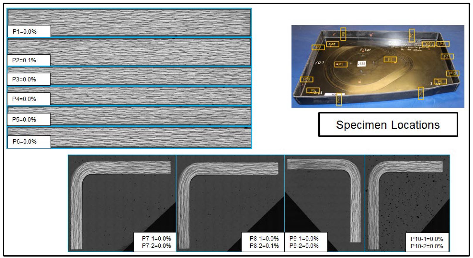
TS-RAPM-002 rib cross-sections for optical porosity investigation. SOURCE | Fig. 3.8, “Spring Frame Press Fabrication of Aerospace Production Components” by Timothy J. Luchini, et. al., SAMPE 2019.
TS-RAPM-003 curved C-channel
This part was 640 millimeters long with a 40-millimeter-deep U-section on the final trimmed piece. The inner radius of the section was greater than the outer radius, and the thickness increased from 6.6 millimeters in the narrow section to 8.8 millimeters at the wide end. Due to its thickness, the C-channel part was substantially heavier than the previous parts discussed. Therefore, the spring-frame required more attachment points than with the previous parts.
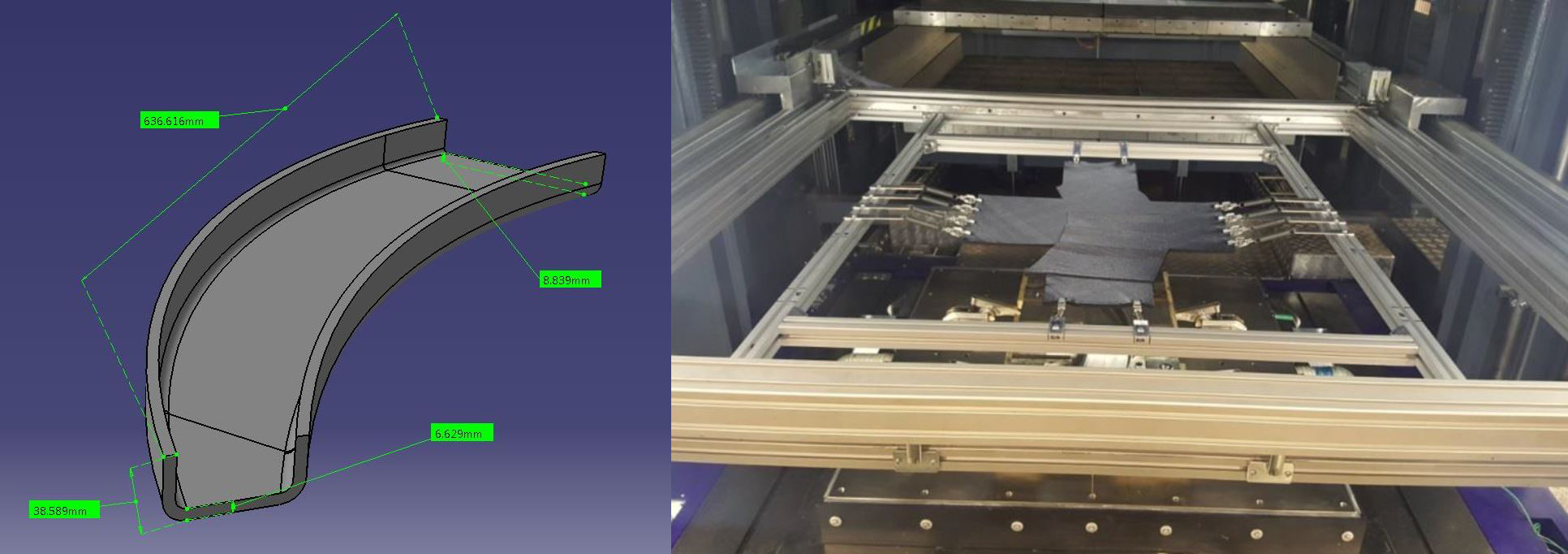
TS-RAPM-003 curved C-channel part geometry and spring-frame configuration. SOURCE | Fig. 14 and 15, “Challenges of Aerospace Structural Part Geometries for High-Rate Compression Molding” by Aurele Bras, et. al., SAMPE 2020.
Double dwell to maintain pressure in thick parts

Fig. 16 – C-scan analysis of initial C-channel parts made using CYCOM EP2750 (top) and preconsolidated CYCOM 5320-1 (bottom).
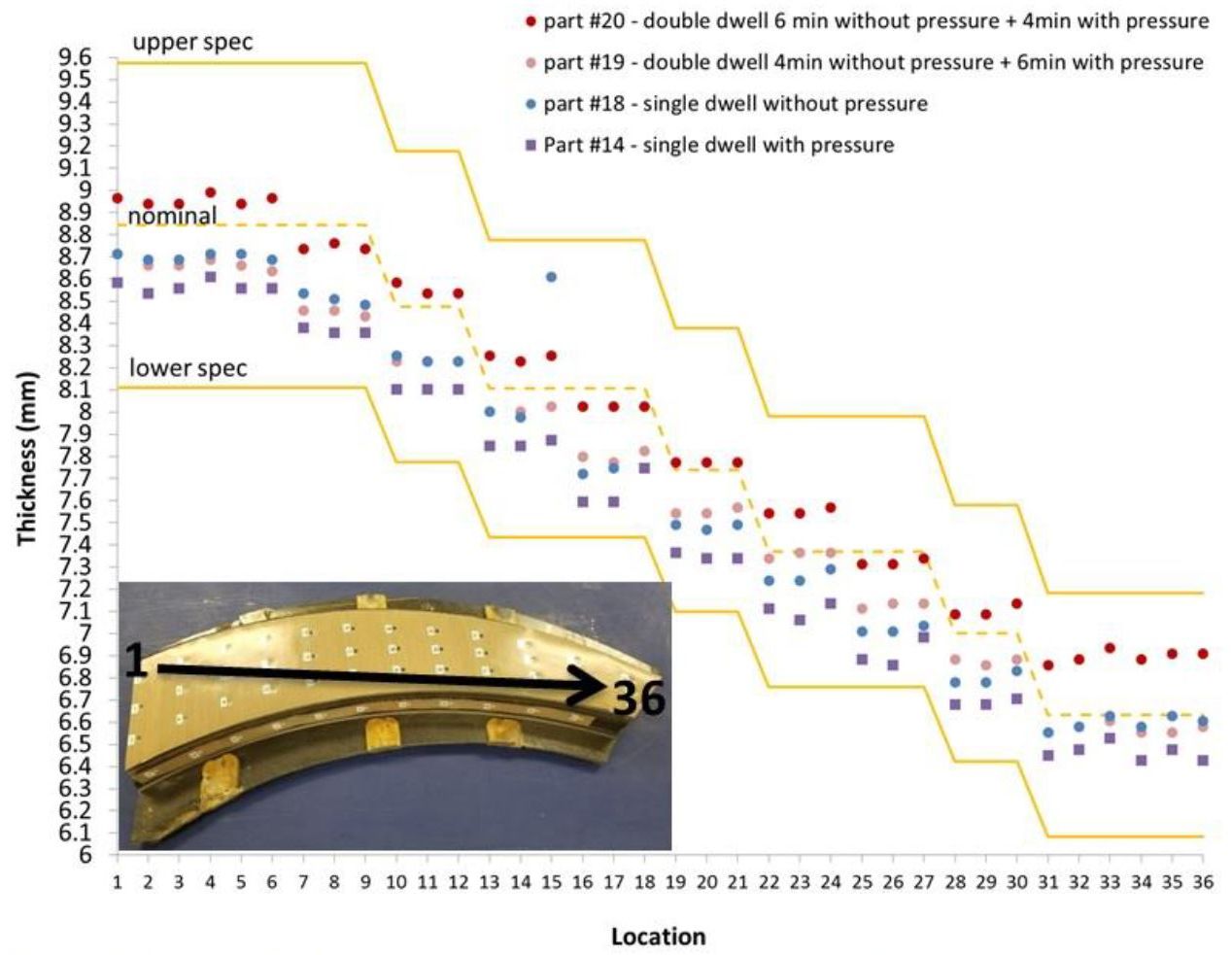
Fig. 18 – Microscope measurement of C-channel thickness vs. location for 36 samples, moving from thick (point 1) to thin (point 36) end of the part.
SOURCE | “Challenges of Aerospace Structural Part ...” by Aurele Bras, et. al., SAMPE 2020.
C-scans of molded parts highlight a wrinkle propagating from the inner radius to the outer radius for parts using preconsolidated blanks. The grey scale indicates the wrinkles also carry porosity.
These wrinkles and porosity were removed for CYCOM EP2750 prepreg parts by using a “double dwell” process. This consists of applying a certain amount of pressure during the dwell immediately following the viscosity build-up of the material. “This was determined using the data provided by the press and the tools during the development of the process,” explains Hahn. “Basically, there are two steps of progressive pressure build-up prior to full pressure application. As a result, the pressure-vs-time profile has a similar shape to the resin viscosity profile. An initial dwell at bulk thickness is used to drive resin viscosity up to prevent a thinning out of the material charge [blank or preform]. If the charge is of significant thickness, two dwells are used to prevent loss of pressure due to resin shrinkage. The first dwell is at a gap of X, and the second at a gap of Y, with Y < X.”
Fig. 18 above shows the effect of double dwell on C-channel part thickness. Matching pressure to resin viscosity enabled more resin to be retained within the part, which wet out the fibers for low porosity and built thickness to reach the required nominal yet maintained low fiber distortion. However, the RAPM team emphasized that this double dwell process is favored only for thicker parts, noting that it can induce CPT unevenness in parts of varying thicknesses.
RAPM lessons learned and further parts trials
The RAPM part trials discussed here has contributed knowledge towards high-rate manufacturing of aerospace structural parts using prepreg compression molding. Lessons learned include:
- Low bulk is beneficial for part quality, specifically to contain porosity levels and increase surface finish in vertical edges. Higher resin content-prepreg, such as CYCOM EP2750, allows a wider manufacturing window, as well as increased process repeatability
- Ideally, press equipment should include an infrared (IR) preheat station, automated carrier frame for shuttling preheated blank/preform to the mold, tight parallelism tolerances between upper and lower press platens, ability to control and monitor the position of the platens to a tight tolerance and the ability to press using low as well as high forces.
- Pre-consolidation of blanks/preforms allows reducing fiber disturbance in vertical walls and contributes to reducing overall porosity levels in molded parts. NOTE this is debulking, NOT preforming on a shaped tool
RAPM has shown that prepreg compression molding can produce high-quality, aerospace-grade structures while reducing cycle time and labor. This enables composites to better compete in trade studies for aerospace applications while delivering increased weight savings and component performance (e.g., resistance to corrosion, cracking and fatigue, etc.).
Solvay and Boeing have worked together to refine the novel EP2750 prepreg system, demonstrating takt times down to 20 minutes, thanks to a combination of material chemistry, prepreg and process knowledge and automation.
TS-RAPM-012 Boeing challenge “wave” part.
SOURCE | Boeing, DARPA, Solvay.
In addition to the Manufacturing Development parts discussed above, RAPM has also produced several Challenge and Transition parts, meant to challenge initial developments and transition candidates with potential to win against machined aluminum in defense applications. These include:
- TS-RAPM-007 Solvay challenge part
- TS-RAPM-008 skin access panel
- TS-RAPM-012 Boeing “wave”
- TS-RAPM-014 motor arm
- TS-RAPM-015 fin
Results and lessons learned from these part trials and other RAPM manufacturing feature studies will be published in 2020/2021.
SOURCE | Slide 10, “Rapid High Performance Molding of Structural xEP-2750 Prepreg for Compression Molding” by Timothy J. Luchini, et. al., SAMPE 2019.
Solvay automotive parts trials
Solvay has also illustrated how EP2750 performs in automotive parts, such as a B-pillar sized 36 by 16 by 2 inches with a thickness of .0725 inches, comprising 5 plies of Solvay THORNEL T650-35 standard modulus 3K tow carbon fiber in a 376 grams/square meter 8-harness satin fabric. This part was made at Solvay Heanor, U.K. using DDF. When compared to autoclaved standard prepreg, the combination of CYCOM EP2750 and DDF offers a 60% reduction in cycle time and 85% in takt time (time between starting one part and the next part on a production line — i.e., the line’s pulse time).
SOURCE | webinar presented by SolvayCW (April, 2020).


Related Content

Call for abstracts: CW Tech Days to explore high-temperature composite solutions
The fall 2025 installment of CW’s Tech Days online event series will cover high-temperature composite solutions for defense and space applications.
Read More
Orbital Composites wins AFWERX award for Starfighter drone fleet
Under the TACFI contract, Orbital is implementing the AMCM process to build 3D printed composite multi-mission UAS aircraft, surpassing $10 million in government awards.
Read More
MATECH C/ZrOC composite is deployed in hypersonic aeroshells
Ultra high-temperature insulating CMC targets hypersonics, space heat shields and other demanding applications, tested up to 2760°C under extreme stagnation pressures.
Read More
Converting carbon fiber for UHTCMC to 3500°C
Advanced Ceramic Fibers LLC demonstrates ultra-high temperature ceramic matrix composites using SiC and other metallic carbides for applications in aerospace, defense, energy and more.
Read MoreRead Next

Revolutionizing the composites cost paradigm, Part 2: Forming
Boeing-led parts trials explore infusion, compression molding and thermoplastics, offering lessons and supply chain options to better compete with aluminum.
Read More
Next-gen fan blades: Hybrid twin RTM, printed sensors, laser shock disassembly
MORPHO project demonstrates blade with 20% faster RTM cure cycle, uses AI-based monitoring for improved maintenance/life cycle management and proves laser shock disassembly for recycling.
Read More
Ultrasonic welding for in-space manufacturing of CFRTP
Agile Ultrasonics and NASA trial robotic-compatible carbon fiber-reinforced thermoplastic ultrasonic welding technology for space structures.
Read More