


This blog is an online sidebar for the May 2020 feature, “Revolutionizing the composites cost paradigm, Part 2: Forming”, which discusses the RApid high-Performance Manufacturing (RAPM, pronounced “wrap-em”) program led by The Boeing Co. (Chicago, Ill., U.S.), the “forming” part of DARPA’s Tailorable Feedstock and Forming (TFF) program to enable rapid, low-cost and agile manufacturing of small, complex-shaped composite parts.
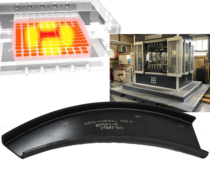
All three material and process tracks in the RAPM program — resin infusion, thermoset prepreg and thermoplastic forming — included trials using a Production to Functional Specification (PtFS) pixelated-heating control and tooling system, supplied by Surface Generation, and located at Boeing R&T in St. Louis (see table below).


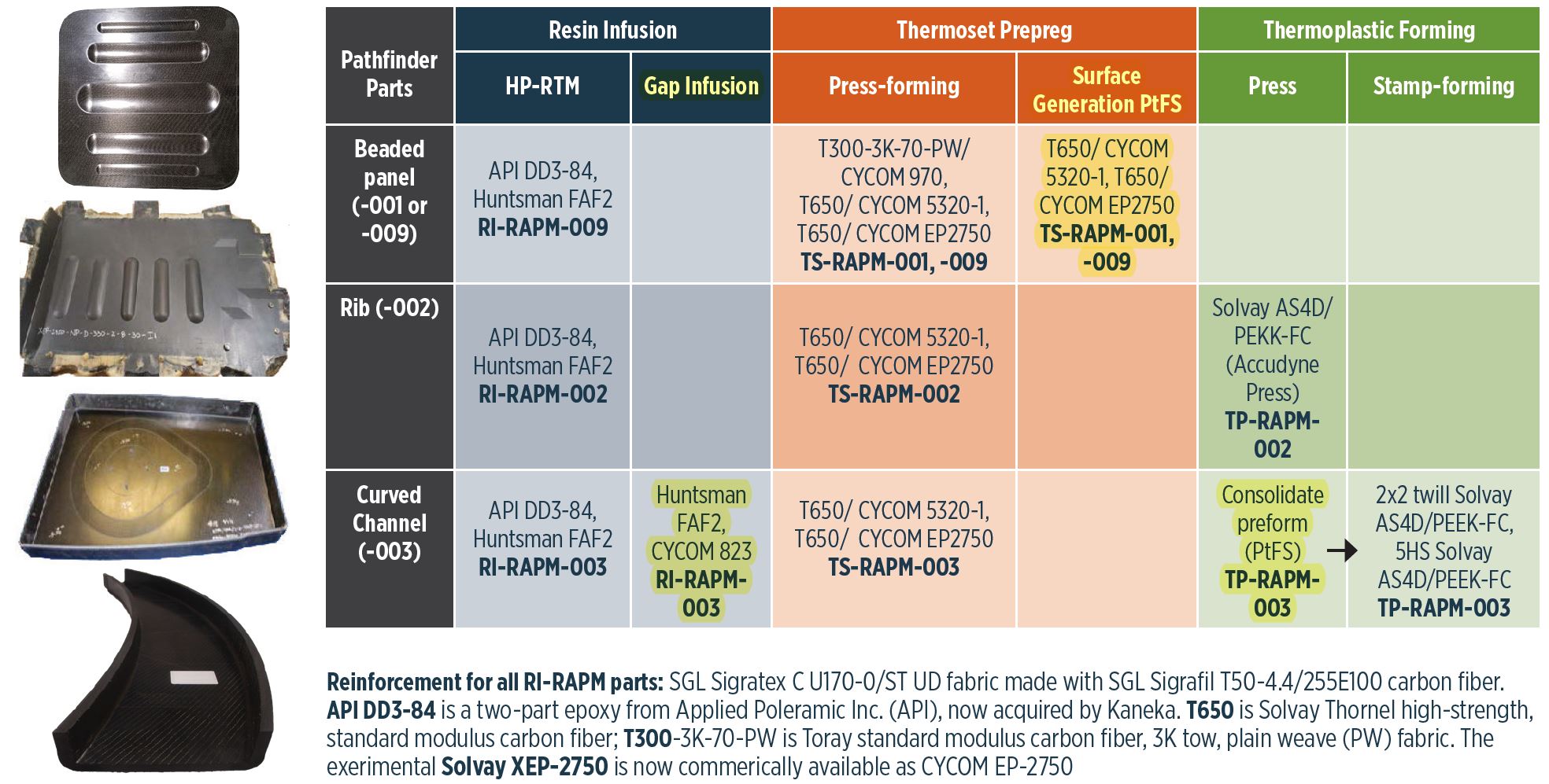
Fig. 1 from CW May 2020 feature, “Revolutionizing the composites cost paradigm, Part 2: Forming”, summarizing initial parts forming trials in the RAPM program with those using the Boeing St. Louis PtFS work cell highlighted in yellow.
Note that PtFS has been commercialized for years. This blog concerns RAPM's process development using the PtFS system. References for this blog include:
- 2019 SAMPE (May 20-23, Charlotte, N.C.) technical paper and slide presentation, “Development of Scalable Dynamic Control Architectures for Flexible Composites Manufacturing Work Cells” by Steven M. Shewchuk1, Ben Halford2, Michael P. Matlack1, Andrew Sharpe2 and Pete Massey2. 1The Boeing Company, St. Louis, Mo., U.S. 2Surface Generation Ltd. (Rutland, U.K.).
- 2020 SAMPE technical paper, “Compression Molding of Complex Thermoset Laminates” by Travis R. Adams, Timothy J. Luchini, Jared B. Hughes, Steven M. Shewchuk, Adam Martinez and Gail Hahn, The Boeing Company.
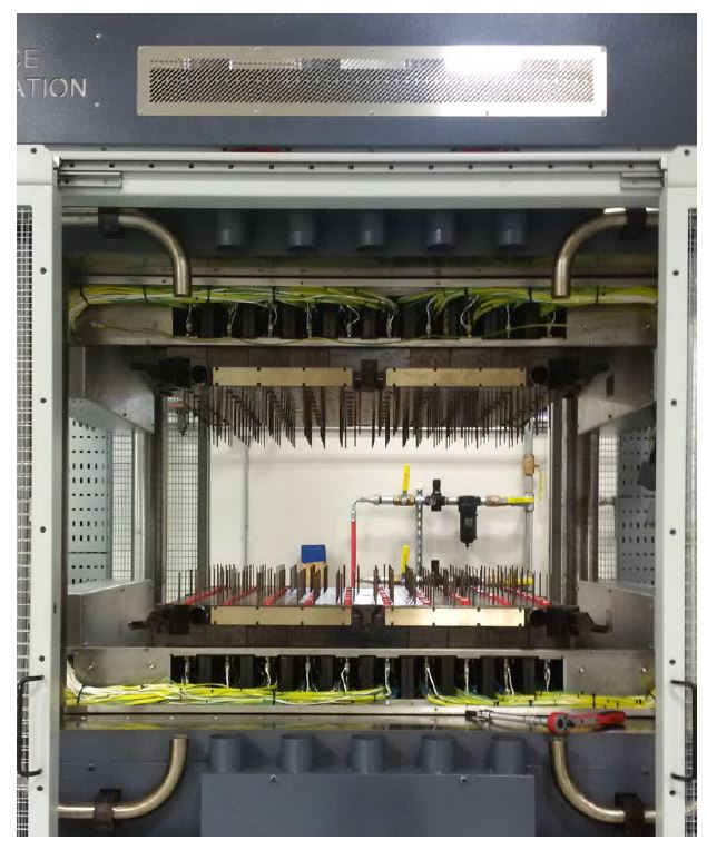
PtFS work cell at Boeing St. Louis used in the RAPM program. SOURCE for all images | Boeing, DARPA. “Development of Scalable Dynamic Control Architectures for Flexible Composites Manufacturing Work Cells” by Shewchuk, et. al. Fig. 1 and Slides 3 and 13. Labels added by CW.
PtFS system components
The PtFS system is modular and can be completely stand alone or use portions of existing infrastructure. For compaction/consolidation pressure, the system can use an existing hydraulic press or a hydraulically actuated tool clamping fixture. The Boeing St. Louis PtFS cell is equipped with the latter, a 150-metric ton clamping fixture designed by Surface Generation. This molding cell accommodates a part volume of 750 by 750 by 100 millimeters.
The Boeing St. Louis PtFS cell includes position and pressure control. “Surface Generation’s Orchestrator software is used to control the CF-OaO-RAPM PtFS work cell,” notes Boeing technical fellow and RAPM program manager Gail Hahn. “Each tool is calibrated in the system through displacement and pressure tuning. Pressure calibration is conducted to tune the hydraulics to the expected pressures the tool will experience during processing. Tool separation and displacement calibration is done to set the open/close position of the tool as well as the slow/fast close regions, which protects the tool face during manual and automatic control.” Positional measurements are completed with four string potentiometers, explains Boeing composite materials engineer and RAPM researcher Steven Shewchuk. “Each one is located at a guide post of the clamping fixture to measure platen position as well to provide a safety method to identify platen racking during operation. The pressure control is completed with a single in-line pressure transducer to provide feedback control to the clamping fixutre’s hydraulic pump.”
Above and below the clamping fixture are top and bottom heater base units. These contain all heating/cooling components and operate in response to outputs from the control cabinets (three cabinets for each heater base in the Boeing setup). Tool faces are designed for each heater base and installed using a rail and loading system.
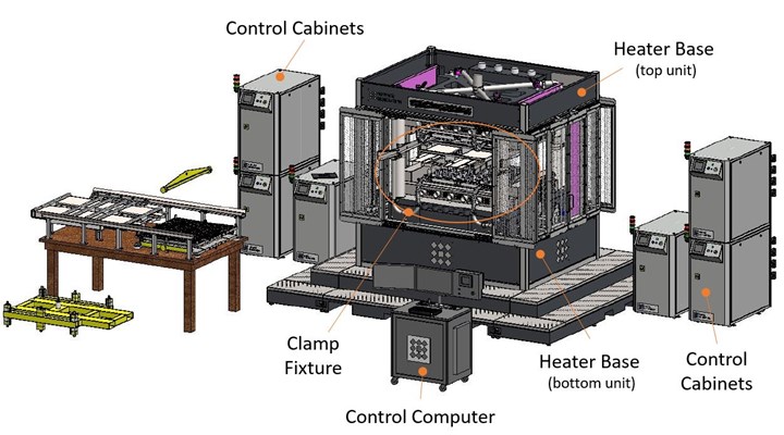
Each tool face is heated and cooled using compressed air directed at the underside of each tool face and dispersed via a diffuser. Each set of matched metal tool faces are divided into 180 individually controllable heater channels — 90 for the top tool face and 90 for the bottom. Heater channels are spaced 10.0 centimeters apart in a grid across each tool face. Each channel has a heater, a two-stage compressed air source and two feedback thermocouples that are spring-loaded to ensure intimate contact with the backside of the tool face. Heating of the RAPM tool faces used 1 cubic foot per minute of compressed air per heater channel while cooling used 3 cubic feet per minute.
Tool face (top left), individual heater channel within each tool face (top right) and heater base with control cabinet (bottom) showing how compressed shop air is directed into the heater base to heat and cool each tool face. SOURCE | “Development of Scalable Dynamic Control Architectures for Flexible Composites Manufacturing Work Cells” by Shewchuk, et. al. Fig. 2, 4, 6 and Slides 5, 6, 7. Compilation and labels by CW.
Tool faces
Tool faces in RAPM were machined from tool steel to a thickness of ≈3 millimeters. The lower tool face for TS-RAPM-001-201 is shown at top left in the figure above. The top of the tool face looks like a standard stamp forming tool, but the underside reveals the heating channels.
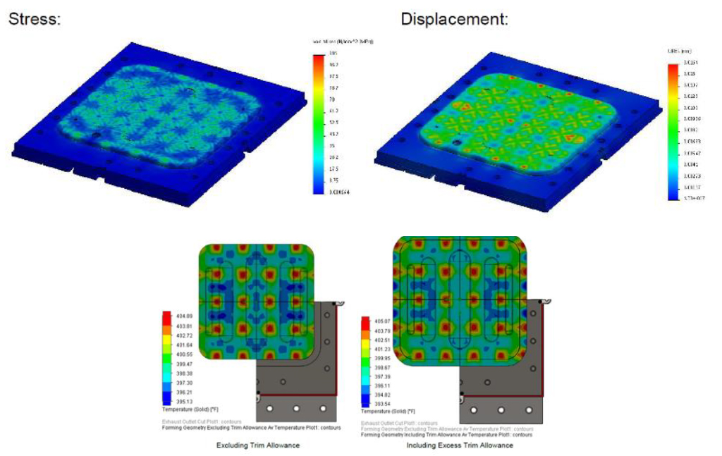
Heater bases installed in the clamp fixture show protruding sleeves which contain spring-loaded thermocouples for each heater channel (top). Because tool faces are machined to remove thermal mass for improve heating/cooling rates, structural as well as thermal analysis must be completed for each (bottom). SOURCE | “Development of Scalable Dynamic Control Architectures for Flexible Composites Manufacturing Work Cells” by Shewchuk, et. al. Fig. 5 and Slide 6.
Tool faces of acceptable geometries can be changed out with other tool faces designed for the same heater base. The tool will need the same heater channel dimensions, approximate thermocouple placement and a depth that will fall within the spring-loaded thermocouple travel.
The rail loading system used to change a tool face aligns all 180 spring-loaded feedback thermocouples into sleeves on the back side of the tool face. Pins align the tool face and allow tool loading to be done without precise forklift control. Tool change can be completed in 2-4 hours with two operators including disassembling and reassembling the tool face into its picture frame.
As much material as possible is machined away in order to reduce thermal mass and improve heating and cooling rates. For this reason, each tool face used in RAPM required structural finite element analysis (FEA) to determine if the tool face could survive the processing temperature and pressure. The tool faces were optimized using linear and non-linear FEA as well as steady-state and transient computational fluid dynamics (CFD) thermal analysis. The latter helped to ensure uniform tool heating. Both the tool thickness and the air diffusers within each heater channel were modified to improve temperature uniformity. An iterative loop between FEA and CFD enabled tailoring geometry to help maintain desired tool face temperature while meeting required factors of safety for tool face support.
Heating zones and temperature control
Heater channels are typically grouped into zones, with the number of heater channels per zone specified per part. Each zone has a heating profile associated with it and tolerances can be set within and between zones as required. This allows all of the heaters in each zone to heat, cool or maintain temperature following its prescribed heating profile by dynamically varying heater power levels and compressed air flow rates.
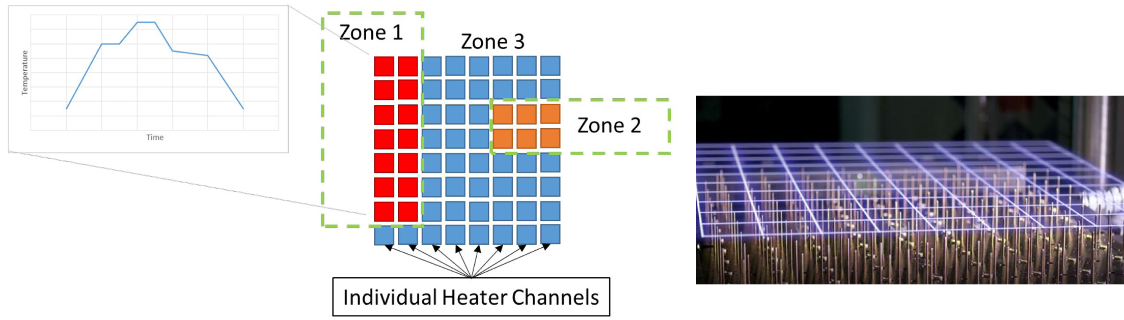
Heater base with channel grid (right). Each heater channel is placed into a zone, and each zone has its own heating profile (left). SOURCE | “Development of Scalable Dynamic Control Architectures for Flexible Composites Manufacturing Work Cells” by Shewchuk, et. al. Fig. 3, 5.
Although the PtFS equipment control software has both analog and digital heating strategies that can be tailored to different heating scenarios, the RAPM cell uses analog control. This requires auto-tuning of the system to determine heater power levels at targeted temperatures. Power levels for each heater are set to prevent over- or undershooting during heating/cooling ramps and to maintain temperature set points. The auto-tune automatically determines constant values for a modified Proportional Integral Derivative control method for every heater channel at each specified temperature. Once the auto-tune is complete, heating profiles can be written for each zone. All thermal profiles were verified to ensure the composite part was exposed to temperatures within ±5.5°C (±10°F) of the desired set point.
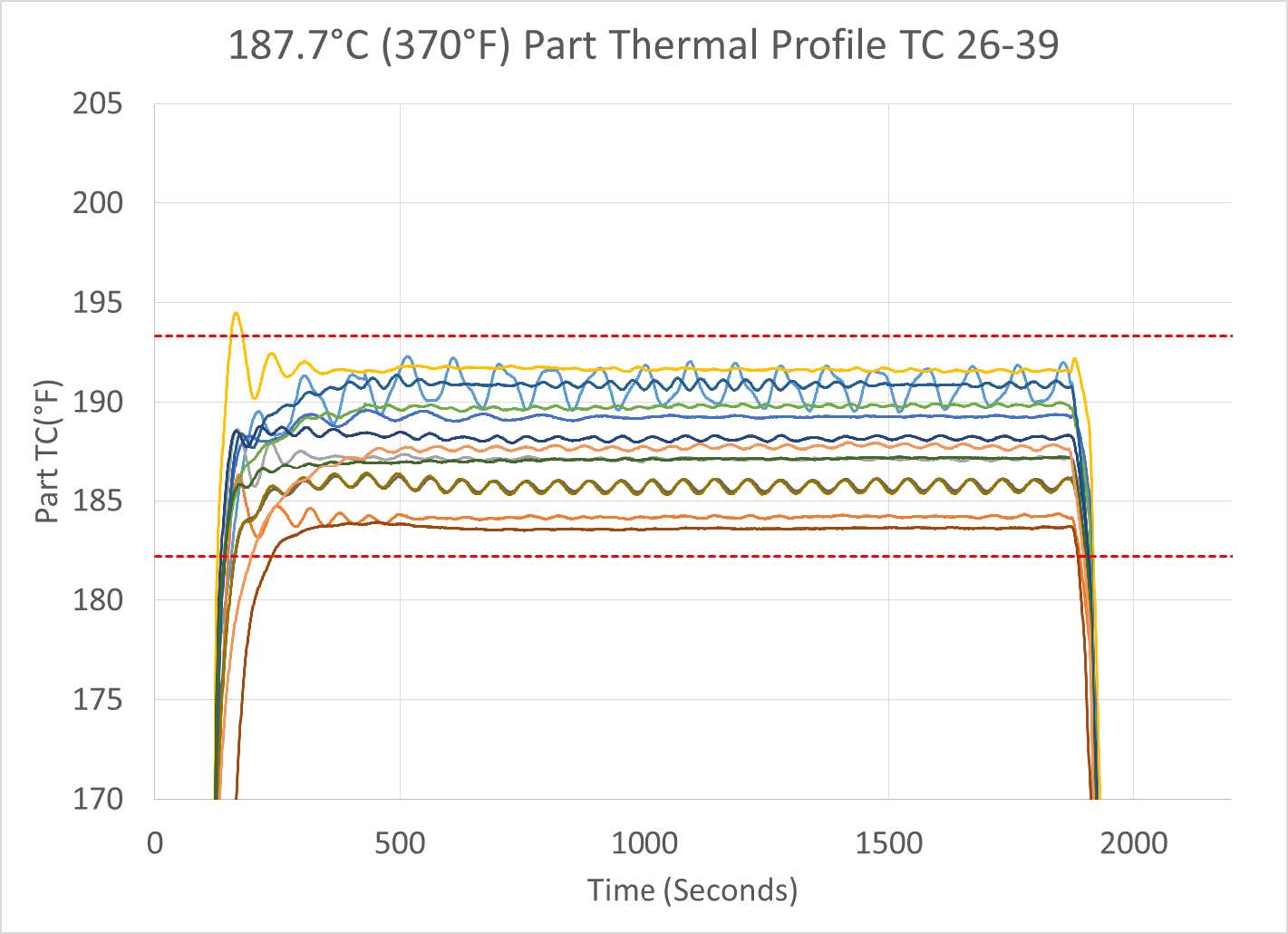
Thermal profiles were verified, using thermocouple measurements, to ensure composite parts would see temps within ±5.5°C (±10°F) of the set point. SOURCE | “Development of Scalable Dynamic Control Architectures for Flexible Composites Manufacturing Work Cells” by Shewchuk, et. al. Slide 9.
The Boeing PtFS cell has a maximum temperature of 440°C. Initially, when Boeing was processing multiple high temperature cycles in a day, there was concern that certain components might be damaged due to lack of cooling between processing cycles. However, the cooling system was upgraded in Sep-Oct 2019, including additional fan capacity for heat extraction. With this improved cooling, the cell can process continuously at 440°C.
Using a large volume of ambient temperature compressed air as the cooling method, tool face cooling was fast near the top end of the temperature range but slowed significantly as it reached 60°C (140°F). During heating to thermoplastic temperatures (>350°C), the tool face temperature ramped at an average rate of 41°C/min (74°F/min). During cooling of the same run, the peak average cooling rate was 36°C/min (65°F/min). Using compressed air for cooling provided a more continuous cooling ramp and combined with active thermal management (i.e. heating when required), the temperature remained fairly linear during cool down.
Isothermal TS prepreg stamping
The first part trials using the PtFS work cell were for TS-RAPM-001 beaded access cover panels made with thermoset prepreg compression molding (stamping). The tool for this part occupies 112 of the 180 channels in the RAPM PtFS work cell. This includes 56 channels on the top tool face and 56 channels on the bottom tool face. The actual part, however, does not cover the entirety of that tool — but only covers 30 of those 56 channels for each tool face, upper and lower. The figure below shows the placement of the 78 thermocouples (TCs) used for RAPM-001 parts — 39 for the top face and 39 for the bottom face with the same placement for both. The number of TCs comprises one per cell (heater channel) plus additional TCs in hot and cold regions identified in the CFD thermal analysis.
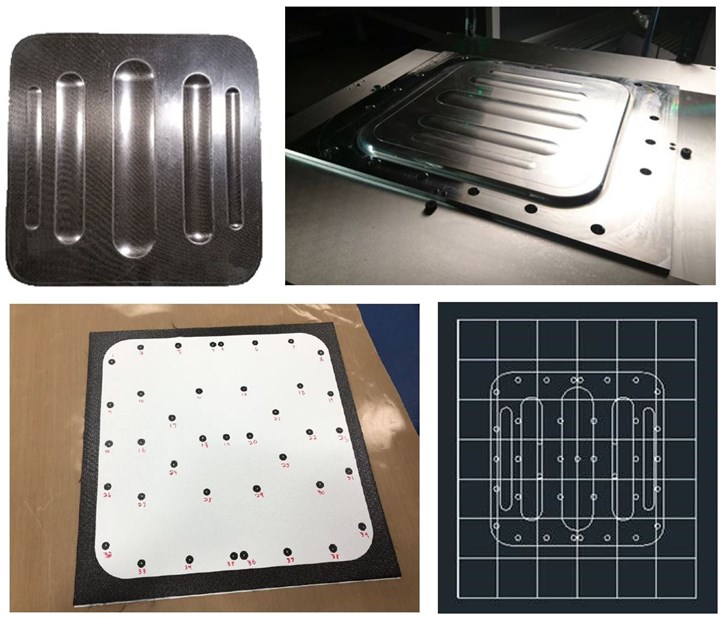
For the RAPM-001 beaded access cover panel parts (top left), top and bottom tool faces (top right) covered 56 of the PtFS work cell’s heater channels but the part only covered 30 of those (bottom right). The thermocouple (TC) placement (bottom images) shows one TC per each heater channel plus 9 additional TCs in hot and cold regions as identified by the CFD thermal analysis of the tool. SOURCE | “Development of Scalable Dynamic Control Architectures for Flexible Composites Manufacturing Work Cells” by Shewchuk, et. al. Fig. 7.
The empty tool face was tested for temperature uniformity and the test was then repeated after embedding thermocouples at the midpoint of a 16-ply carbon fiber woven/epoxy laminate. Once composite material is added, the tool face temperature distribution becomes tighter as the composite acts as a heat transfer path. Also, the temperature uniformity within the composite laminate was tighter than the tool face readings. The single TC in Run 1 (see the figures below, top of the chart on the right) that oscillated above the desired temperature range was near the part edge and is suspected to have been caused by temperature fluctuations of neighboring cells outside the part trim line.
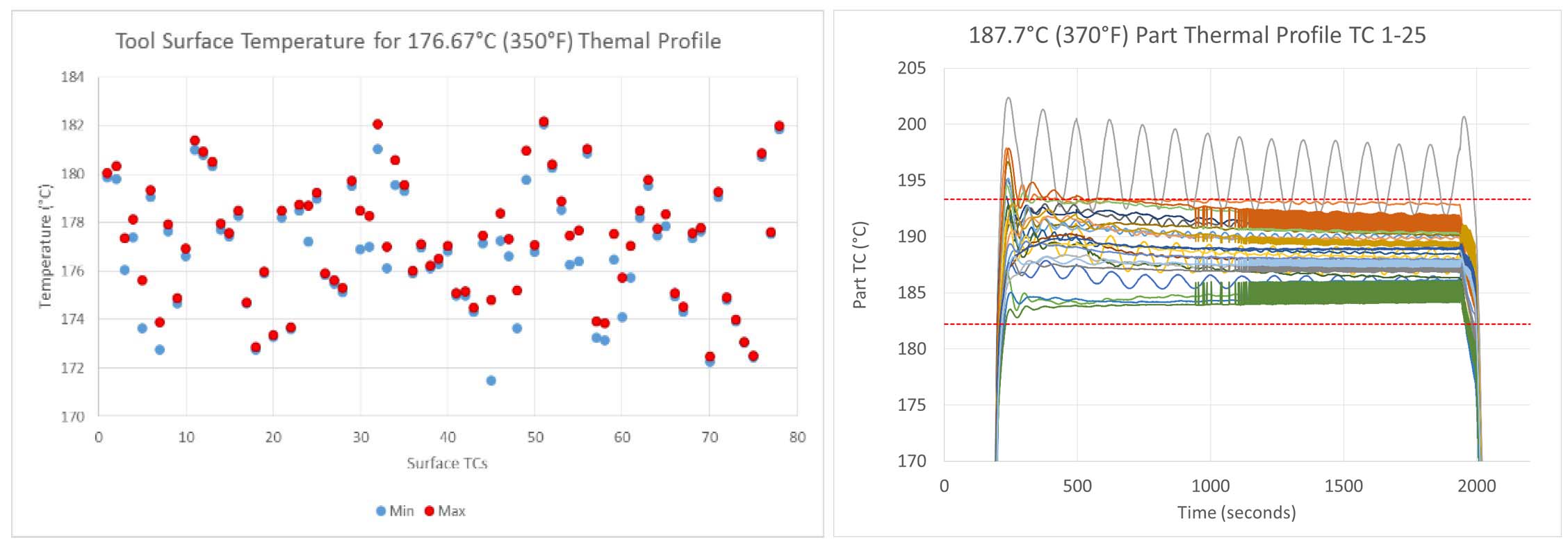
Thermocouple measurements of empty tool face temperature test (left) and during part cure (right), with green showing the composite part temperature. The single thermocouple that oscillated at the top of the graph was near the part edge and suspected to be due to temperature fluctuations of neighboring cells outside the part trim line. SOURCE | “Development of Scalable Dynamic Control Architectures for Flexible Composites Manufacturing Work Cells” by Shewchuk, et. al. Fig. 9, 10 and Slides 8, 9.
Isothermal compression molding of the processing held the tool at 176.7°C (350°F) within the ±5.5°C (±10°F) tolerance. For TS-RAPM-001, the following sequence was followed:
- System heats to 187.7°C in app. 8 minutes
- Composite blank loaded into hot tool
- Tool closed at 12:09 (for example)
- 30 minutes time on tool to gel composite
- First pressure stage: initial rapid heating of blank while minimizing resin squeeze out
- Second pressure stage: ramp to 300 psi to ensure good consolidation and prevent void growth
- Remove “green” composite from hot tool for post-cure
This process did achieve high-quality parts and demonstrate lower cycle time parts than current composites processes. A higher process temperature could gel the composite even faster but may also cause material degradation and risk of exotherm. This was a concern because PtFS tooling does not use traditional large thermal mass to absorb exotherm but instead relies on active cooling of the back side of low thermal-mass tools to dissipate exotherm.
The PtFS cell was also used to make TS-RAPM-012 “wave” challenge parts. Using prior development trials, it was determined to cure these parts using a 30-minute isothermal cycle at 177°C followed by a 2-hour post-cure at the same temperature. Differences from previous trials, however, included a more aggressive geometry and a quasi-isotropic lay-up using CYCOM 5320-1 epoxy — standard for out of autoclave aerospace parts — combined with 8-harness satin and unidirectional carbon fiber layers and an outer ply of Style 108 woven glass fabric on one side. The RAPM PtFS controller was programmed to apply a minimal amount of pressure on the laminate until a proper viscosity was achieved. After this initial step, final pressure was applied to finish out the cure. One trial was post-cured in an oven, while the rest were post-cured in the PtFS clamping fixture to reduce time between trials. Multiple high-quality parts were produced.
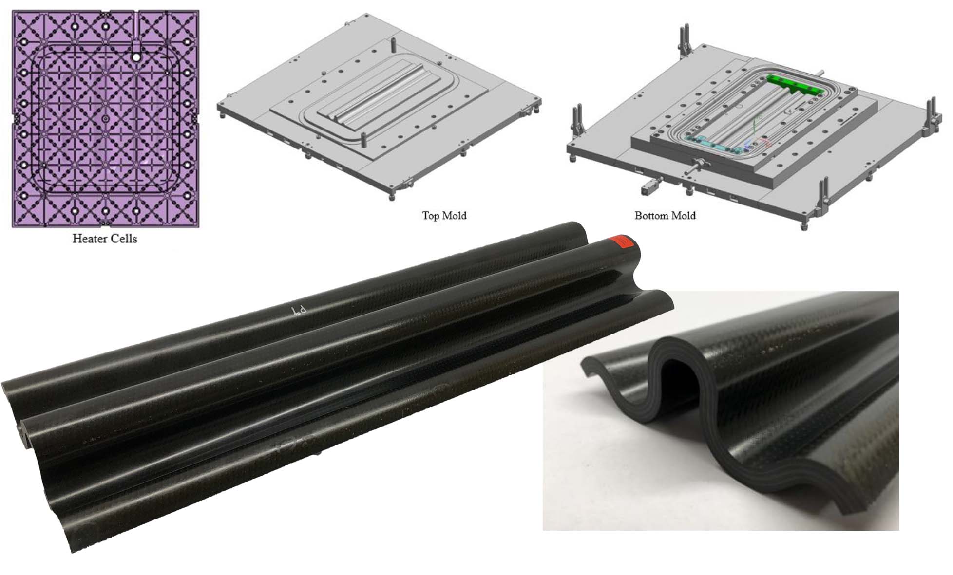
TS-RAPM-012 challenge parts were also made using the PtFS molding cell. SOURCE | Fig. 4 and 8, “Compression Molding of Complex Thermoset Laminates” by Travis R. Adams, et. al., SAMPE 2020.
Dynamic temperature cycles for resin infusion
Resin infusion part trials using the PtFS work cell began with the RI-RAPM-003 curved C-channel part. Three different epoxy resin systems were initially trialed:
- Solvay CYCOM 823, infused at 80° and then ramped to dwell at 125°C
- Huntsman FAF2 (quick-cure system) infused at 100°C with 150°C dwell
- Applied Poleramic (now acquired by Kaneka) API DD3-84 (also a quick-cure system) infused at 60°C with a dwell temperature of 160°C.
The noncrimp fabric preform was infused, ramped at 2°C/min to the specified dwell temperature and then held for 60 minutes before cooling. For the quick-cure resins, as the exothermic reaction progressed, the PtFS automatically applied active cooling to specific tool regions to maintain specified part temperatures.
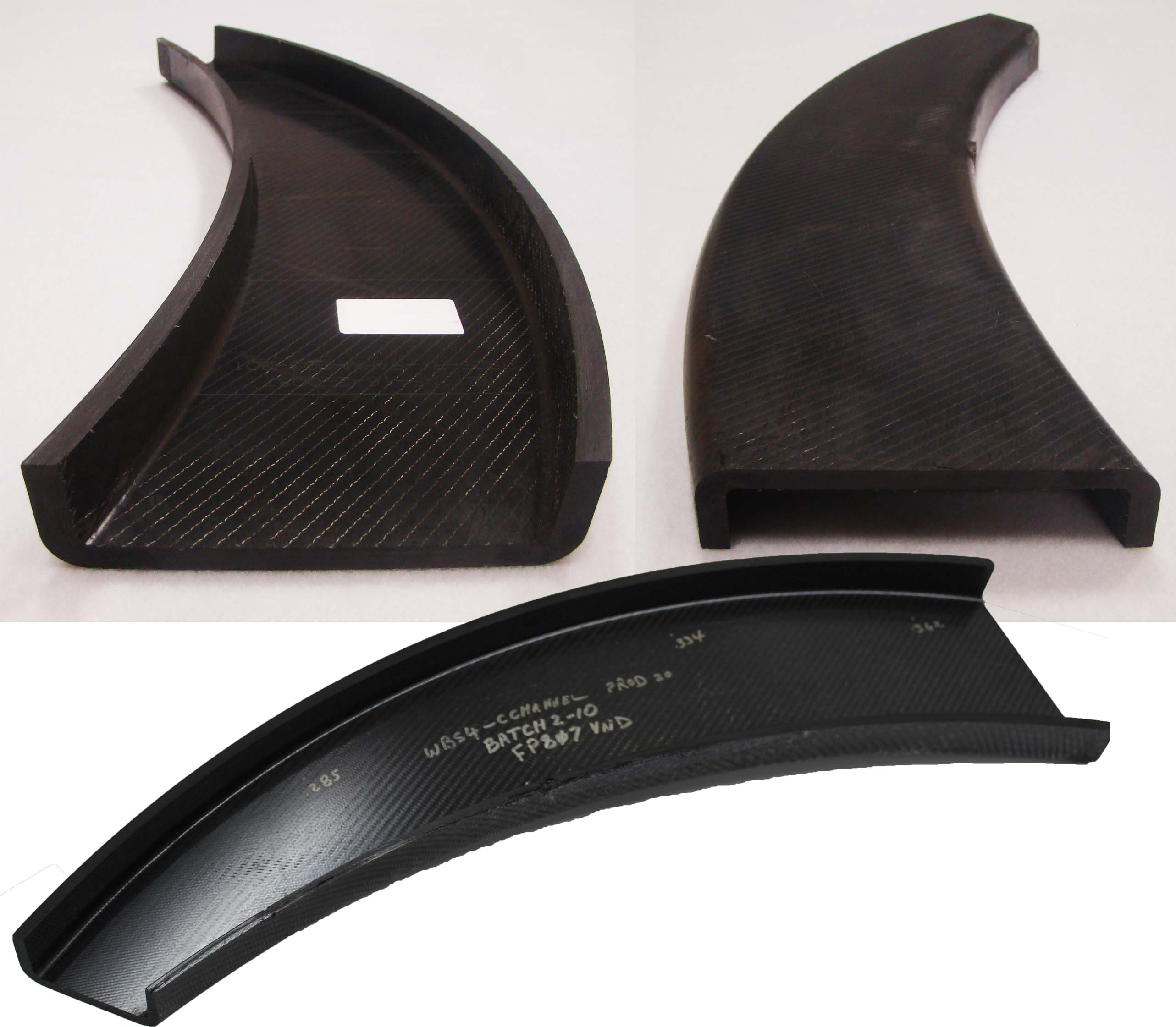
RI-RAPM-003 parts made using the PtFS molding cell. SOURCE | Boeing, DARPA.
The PtFS equipment was also able to provide the positional control to support a gap infusion method for the RI-RAPM-003 parts. In this method, the tool was closed to an initial height of the vacuum gasket, allowing the tool to remain open 1.3 millimeters during infusion. After infusion was complete, the tool was then closed the remaining distance to drive the resin into the preform in the z-direction. Parts were made successfully using this process.
Dynamic temperature control for thermoplastic stamping
The PtFS equipment was also used to make the RAPM-003 curved C-channel in thermoplastic composites. Specifically, it was used to consolidate a complex preform, which dropped from 32 to 24 plies along the length of the part, into a flat blank with a tapered cross-section. The consolidated blanks were then sent to ATC Manufacturing (Post Falls, Idaho, U.S.) which stamped the final part with vertical flanges.
The material consolidated for the TP-RAPM-003 curved C-channel was a carbon fiber 2x2 twill fabric powder-coated with polyetheretherketone (PEEK). The PtFS work cell was used to superplastic form an AZ31 magnesium bladder over the thermoplastic charge, heating the bladder and charge to a PEEK process temperature of 400°C in app. 55 minutes.
At this forming temperature, argon gas was applied to the bladder, which applied consolidation pressure to the thermoplastic composite material. The cell then cooled the bladder and charge to below the PEEK crystallization temperature in 30 minutes, for a total cycle time of 3 hours.

SOURCE | Slide 11 from SAMPE 2019 presentation, “Development of Scalable Dynamic Control Architectures for Flexible Composites Manufacturing Work Cells” by Steven M. Shewchuk, et. al.
Slide 11 above shows the progression in applied pressure during the superplastic forming of the bladder and consolidation of the thermoplastic — increasing from 20 psi to 140 psi after the bladder reached superplastic forming temperature, which was maintained through the cooling. Preforms were successfully consolidated and sent to ATC Manufacturing where parts were stamped for this extremely challenging geometry.
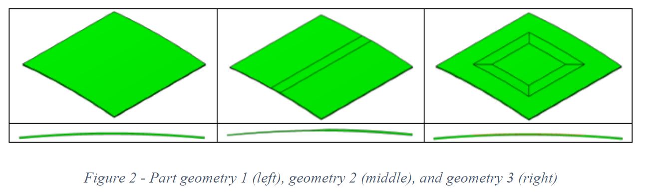
Three different geometries for TP-RAPM-017 also made using the PtFS work cell, but in a one-step process stamping blank to final part. SOURCE | Figure 2 from SAMPE 2020 technical paper, “Thermoplastic Composite Processing Using Superplastic Formed Magnesium Bladders” by Steven M. Shewchuk, Jared B. Hughes, Corey M. Vasel and Gail L. Hahn, The Boeing Company, Saint Louis, MO.
The PtFS cell was also used for one-step blank-to-part stamping of TP-RAPM-017 panels made from a balanced and symmetric layup of unidirectional (UD) carbon fiber/polyetherketoneketone (PEKK) tape in a study of how various options and part features affect bladder forming. The TP-RAPM-017 panels measured 40.6 by 40.6 centimeters with a gentle contour reaching 1.3 centimeters in height. Three different part geometries were evaluated — flat (no ply drop), single-direction ply drop and picture frame — having 32 plies in thick regions, 16 plies in thin regions and a 20:1 ply drop ratio in between. The part cycle time was 1.5 hours for all geometries.
The tool faces were machined from Invar 42 to best match the thermal expansion of the UD thermoplastic composite tape. UD tape ply kits were cut and collated, ultrasonically welded together and placed into the cure tool, where they were heated to 385 ± 15°C. Various pressure cycles were tested, and the part was then cooled to below 220°C, after which pressure was released and the part was demolded.
One example of a pressure cycle for geometry 1 was 20 psi at room temperature, ramp to 140 psi after lagging thermocouple reached melt temperature of 310°C and then cooled at 10°C/minute under pressure until the part thermocouple measured below 220°C. Initial pressures of 20 psi, 30 psi, 50 psi and 70 psi were trialed. Pressure ramps were also varied from 10 psi per minute to 10 psi per 15 seconds, up to the maximum pressure of 140 psi.
One notable result was that all of the panels showed poor C-scan results where the plies were ultrasonically tack-welded. Thus, for best results, such tack-welds should be located outside of the part net trim line. Acceptable parts were produced but some parts showed poor consolidation at the edges of plies. This was remedied by increasing initial compaction pressure to 30 psi prior to heat up. However, this increase in pressure did cause some surface roughness/matte finish on the bladder side of the part. Also, some geometry 2 panels made using the 50 and 70 psi initial compaction pressures showed wrinkles down the center of the parts. It was believed these higher pressures may have prevented the plies from sliding past each other during processing, thus trapping the wrinkle in the parts.
Another variation tried was replacing argon gas with cheaper nitrogen gas for pressuring the bladder, but this also decreased part quality, including surface roughness/matte finish which caused higher levels of attenuation in C-scan results, even though no porosity was found in cross-sections.
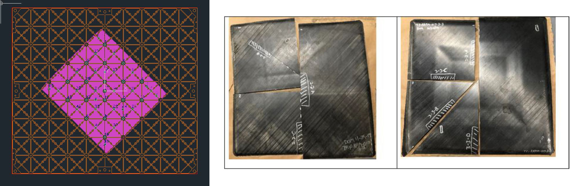
Diagram showing how the TS-RAPM-017 part fit across the heater channels of the metal tool face for the PtFS work cell (left) and cross-sectioned parts from geometry 2 and 3 (right). SOURCE | (left) Slide 12 from SAMPE 2019 presentation, “Development of Scalable Dynamic Control Architectures for Flexible Composites Manufacturing Work Cells” by Steven M. Shewchuk, et. al. and (right) Figure 14 from SAMPE 2020 technical paper, “Thermoplastic Composite Processing Using Superplastic Formed Magnesium Bladders” by Steven M. Shewchuk, Jared B. Hughes, Corey M. Vasel and Gail L. Hahn, The Boeing Company, Saint Louis, MO.
Pros and cons of PtFS in RAPM
The PtFS work cell did demonstrate rapid heating (<10 minutes for epoxy curing at ≈180°C). When combined with automated tool changes, this could enable quick part changeovers and reduce the cost of composite parts for short manufacturing runs. PtFS is also well-suited for high-temperature dynamic runs (as opposed to isothermal part cycles).
The capability of the Boeing St. Louis PtFS cell was increased significantly during the RAPM program, thanks to improved software upgrades for better thermal uniformity and clamp fixture control, improved cooling capability and thermocouple control, as well as an automated pressclave pressure control system. Further capability increase may be possible from using the vast amount of data generated and recorded by the system every second, including each heater channel set point, heater power lever, compressed air level, etc. Applying machine learning to this data could generate part quality and process improvements. Further software enhancements could also allow this data to identify processing anomalies such as excessive energy required and low responsiveness of specific tool locations.
“PtFS provides a great deal of customization as the name implies: Production to Functional Specification,” says Hahn, “but that customization can require investment of time to establish and ‘tune’ the system for a new tool/part configuration.” Most of the machined metal tool face designs for RAPM were produced by Surface Generation in the U.K. However, Boeing and Surface Generation did “train” a U.S. tool designer and a U.S. tool manufacturer to demonstrate that mold-face design could be conducted in the U.S. by sources other than Surface Generation. That tool mold-face, CMD-TP-RAPM-008-503, has been used successfully to make TP-RAPM-008-203 short fiber access panels.
“While some form of temperature control in the tool and/or part helps in all composites part molding,” explains Hahn, “what is actually required is control of temperature at critical areas and times, and this varies per part and process. Thus, understanding the temperature control actually required to form a given part is key. The 180 zones in PtFS are helpful, but also expensive because each demands a machined channel in the tool. If the part only needs an outer and inner zone or a specific zone along a trigger-point geometry, then a different solution may be more affordable. This does, however, open the debate as to what is the best approach to develop a composites part manufacturing cell which is flexible across multiple types of processes and parts.”
Boeing and DARPA will continue adding information to this debate as they finish the RAPM program in 2020 and publish further results.


.jpg;maxWidth=300;quality=90;format=webp)


Related Content

One-piece, one-shot, 17-meter wing spar for high-rate aircraft manufacture
GKN Aerospace has spent the last five years developing materials strategies and resin transfer molding (RTM) for an aircraft trailing edge wing spar for the Airbus Wing of Tomorrow program.
Read More
Materials & Processes: Fabrication methods
There are numerous methods for fabricating composite components. Selection of a method for a particular part, therefore, will depend on the materials, the part design and end-use or application. Here's a guide to selection.
Read More
Composite rebar for future infrastructure
GFRP eliminates risk of corrosion and increases durability fourfold for reinforced concrete that meets future demands as traffic, urbanization and extreme weather increase.
Read More
A new era for ceramic matrix composites
CMC is expanding, with new fiber production in Europe, faster processes and higher temperature materials enabling applications for industry, hypersonics and New Space.
Read MoreRead Next

Revolutionizing the composites cost paradigm, Part 2: Forming
Boeing-led parts trials explore infusion, compression molding and thermoplastics, offering lessons and supply chain options to better compete with aluminum.
Read More
From the CW Archives: The tale of the thermoplastic cryotank
In 2006, guest columnist Bob Hartunian related the story of his efforts two decades prior, while at McDonnell Douglas, to develop a thermoplastic composite crytank for hydrogen storage. He learned a lot of lessons.
Read More
CW’s 2024 Top Shops survey offers new approach to benchmarking
Respondents that complete the survey by April 30, 2024, have the chance to be recognized as an honoree.
Read More