

Share
Read Next


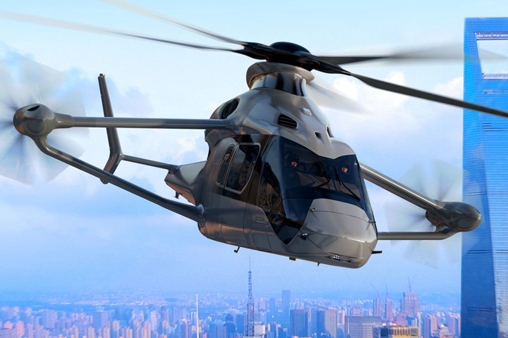
Photo Credit: Airbus Helicopters
Airbus Helicopters (Marignane, France) unveiled the rapid and cost-effective rotorcraft (RACER) concept in June 2017, with an aim to achieve an almost mythic combination of optimized vertical takeoff, hover and fast speed in forward cruise. The company’s previous X3 demonstrator had proven the ability to achieve such performance using a compound aerodynamic configuration — a traditional main rotor combined with innovative lateral rotors. RACER has added pusher propellers at the end of V-shaped box wings and improves hovering via an asymmetric H-shaped tail boom. RACER is also designed for speed, achieving a 400-kilometer/hour cruise versus a 260-kilometer/hour top speed for the average helicopter. Its goal is to improve performance in emergency medical and search/rescue missions, increasing survival by reaching people within the first critical “golden hour” of need.
RACER is one of two concepts in the Clean Sky 2 (CS2) program’s Fast Rotorcraft innovative aircraft demonstrator platform (IADP). The other is the next-generation civil tiltrotor (NextGenCTR) demonstrator. As part of CS2, RACER is being developed and built by 25 multi-partner consortia across Europe and its design also focuses on improved sustainability, including 20% lower CO2 and NOx emissions, reduced noise compared to current helicopters and up to a 25% reduction in purchase price and operating costs.


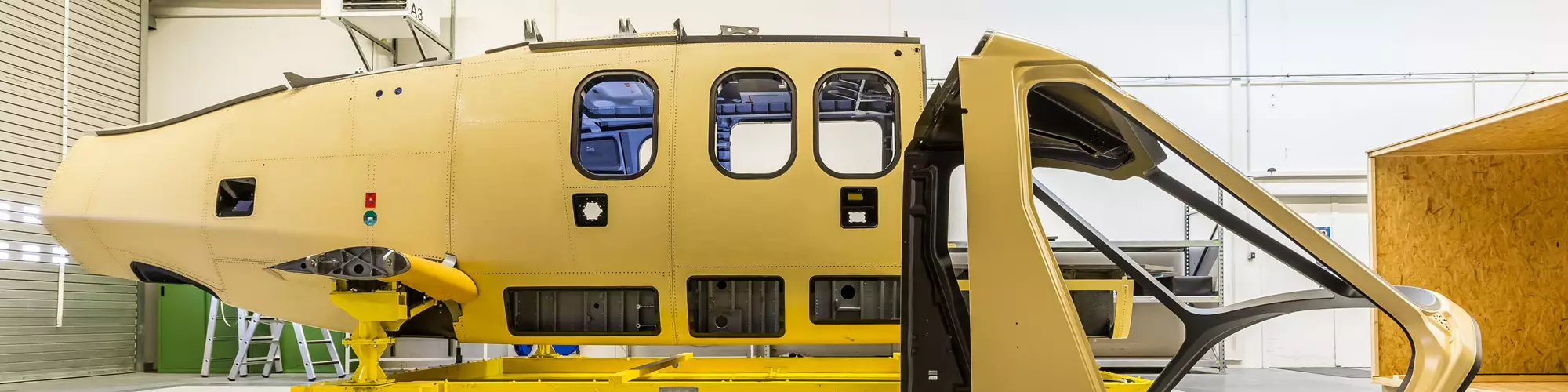
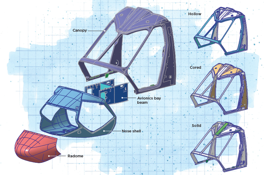
A key contribution to RACER’s advances is its airframe design, which includes the forward fuselage, optimized for low-drag aerodynamics, impact resistance and maximized field of view for pilots, all while minimizing cost and weight. RACER’s forward fuselage comprises four carbon fiber-reinforced polymer (CFRP) parts: radome, center shell/nose shell, avionics bay beam and cockpit shell/canopy.
RACER forward fuselage feature one-piece canopy. Illustrated by: Susan Kraus
Design and manufacture of these components were awarded to the FastCan consortium consisting of Hohenthann, Germany-based KLK Motorsport and Modell und Formenbau Blasius Gerg GmbH (Gerg M&F). Both companies have extensive composites expertise, but mostly from the motorsport and automotive industries, not rotorcraft or aerospace. “When KLK Motorsport answered the call, it was clear that their know-how in automotive design would have relevance and add an extra dimension to this project,” explains Clean Sky FastCan project officer Andrzej Podsadowski. “It was obvious that bringing fresh thinking from outside of aviation and their understanding of how to design a lightweight, impact-resistant, low-cost solution would be beneficial for FastCan.”
“For our company and Gerg M&F, this was an opportunity to open up new markets,” says Kaspar Krause, CEO of KLK Motorsport. “Our goal was to become established partners for the design, development and manufacturing of innovative aerospace components and systems.” KLK Motorsport served as FastCan coordinator and was responsible for design of the canopy structure, including optimized material layup and testing for aerodynamic performance and impact resistance, while Gerg M&F handled design and manufacturing of the tooling as well as fabrication of a flightworthy composite forward fuselage, ready for assembly.
Developing an integrated design
The initial design for the RACER forward fuselage was supplied by Airbus Helicopters. It was assembled from multiple components, says Christoph Stark, project manager at Gerg M&F, “including roof, canopy frame, side pillars and window surround, as well as the lower shell, which was also multiple pieces, and then the radome. We increased the degree of integration, ending with three main pieces plus the beam for attaching the avionics. That was our biggest idea behind the design evolution — to reduce interfaces and make it lighter.” The team integrated the roof structure into the canopy, adds Krause, “and the canopy itself was made as a single-piece component with mainly hollow sections, but also sandwich and monolithic sections. This was also one of the manufacturing challenges — to get this complex part molded with internal bagging [for the hollow sections] in a single cure cycle.”
For the canopy, Nomex honeycomb core (Schütz Composites, Selters, Germany) with a density of 48 kilograms/cubic meter was used in the roof and side pillars while the sections surrounding the windscreen and doors were hollow. Solid CFRP inserts were used for brackets at the bottom of the cockpit doors. All of the nose shell used the same honeycomb core as in the canopy, with monolithic edges. There was also a central “H” shaped reinforcement at the front, stiffening cutouts at both sides and lower front. This was cored with Rohacell foam, supplied by Evonik (Essen, Germany) because the cross section was too small for inserting an internal vacuum bag to make it hollow. The top section of the radome was honeycomb-cored carbon fiber while the radar cone/window was solid glass fiber laminate for radar transparency; it was 8 millimeters thick to meet Airbus Helicopters’ bird strike impact requirements. The avionics support comprises two side panels and one bulkhead, all made from honeycomb-cored carbon fiber prepreg with solid inserts for attachments; it was cured in one shot.
Carbon fiber-reinforced epoxy prepreg was used to build all forward fuselage components except for the radar cone. “We chose Hexcel [Stamford, Conn., U.S.] HexPly M18-1 carbon fiber prepreg with 180°C cure epoxy because it was already qualified and used a lot by Airbus,” says Stark. Hexply 1458 glass fiber prepreg was used for the radar cone.
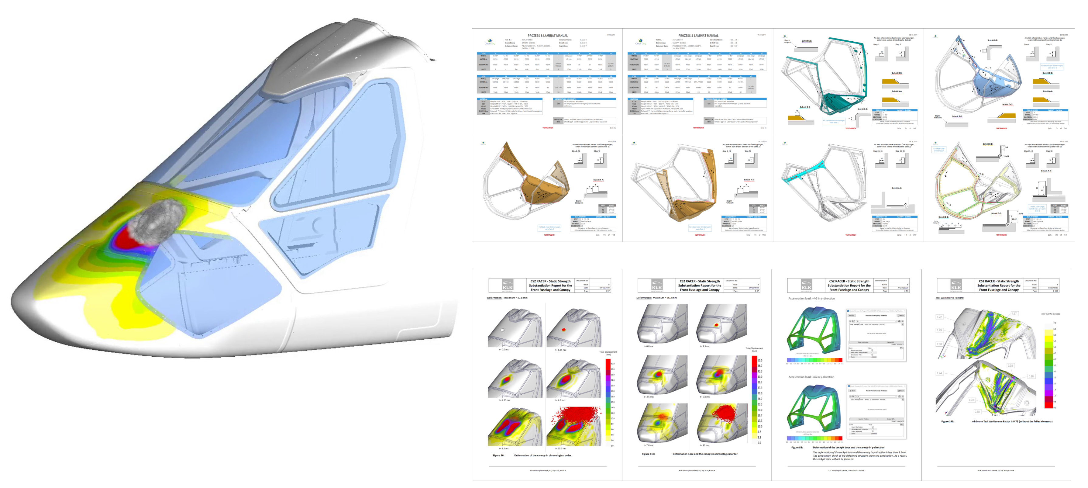
Fig. 1. Complex canopy design
KLK’s FE modeling of all loads for the forward fuselage included bird strike simulations on 19 impact positions and 250 pages of strength substantiation (upper right). Gerg M&F completed tool design and process verification, assisting with the 350 pages and 10 plybooks for the canopy layup (lower right). Photo credit: KLK Motorsport
Detailing the canopy design
KLK Motorsport began with finite element analysis (FEA) to simulate all required load cases and optimize the forward fuselage structures and material layups accordingly. The canopy would be the most complex. “We had a full finite element simulation model of the canopy,” explains Krause, “and checked the complete load envelope: static loads, dynamic loads and bird strike simulations. We also had to build the testing pyramid, starting with coupons [e.g., tensile, shear and compression tests for UD and honeycomb-cored laminates] and then moving up to elements, such as three-point bending tests on the central spar. For these, we crushed samples to complete breakage and compared our simulation models, also in regard to the failure behavior.”
Krause explains that for the sizing of the forward fuselage components, material qualification was important and extensive. “Especially for the combination of CFRP and honeycomb, we were required to show that the simulation forecast was correct. This was done via digital and physical testing pyramids. Especially for the dynamic simulations, but also for the linear static sizing, we had to establish correct material cards showing failure at the correct load level and for the correct failure modes.”
It would seem with such large cutouts for the windshield, the canopy would indeed be highly stressed. “Usually not,” notes Krause, “but if you have a bird strike hitting the center spar, then you do have a large load. And that is the main loading for this part of the canopy.” To test this, “jelly bird shots” (birdlike projectile tests) were performed at FastCan partner German Aerospace Center (DLR) Institute of Structures and Design in Stuttgart to simulate a 1-kilogram bird at a speed of 220 knots. “Those test results were compared to our simulation models, which showed very similar behavior,” says Krause. “We did the bird strike simulations on 19 different impact positions, and that was actually the main driver for sizing — to make the canopy strong enough for all those bird strikes.”
The central spar was the thickest part of the canopy at 4 millimeters. But many areas of the canopy were less than 1 millimeter thick, says Krause. “The outer shell was really stepped and tailored to strength requirements, which required quite high-fidelity simulation models in order to reinforce locally versus globally for bird strike. We achieved function and component integration with tailoring of materials.” Though the combination of materials tailoring and a variety of bird impact simulations seems very complex, he notes that KLK’s motorsport crash simulations are typically much larger and more complex versus these bird strike simulations.
In addition to bird strikes, KLK also applied the aerodynamic and flight loads received from Airbus Helicopters in FE modeling and physical testing. “We generated 250 pages of strength substantiation,” notes Krause (Fig. 1). “There was a lot of documentation for the bird strikes at different positions but also for many other load cases that had to be simulated and proven.” He points out that the canopy could not be designed and dimensioned without the RACER’s windscreen and cockpit doors. “Those were the responsibility of other project partners. So, we exchanged our simulation models with our partners, integrated the windscreen and the doors into our model and then also simulated the jelly bird shots on those.”
Multi-piece tooling for one-piece canopy
Once the design was finalized and approved by Airbus Helicopters, the FastCan consortium began manufacturing. “We actually began developing the tooling concept with the design analysis from the beginning,” Stark points out. This is because the laminate schedule of the hollow, cored and monolithic areas of the canopy required specific overlapping or dovetailing of prepreg plies, as well as internal vacuum bagging for the hollow sections. The use of hollow and cored sections to reduce weight is something KLK and Gerg M&F were quite accustomed to for intricate motorsport structures. “But this was really new for Airbus Helicopters,” says Stark, “to have hollow, monolithic and honeycomb-cored sections in a single part which are all cured together in a single cure cycle.”
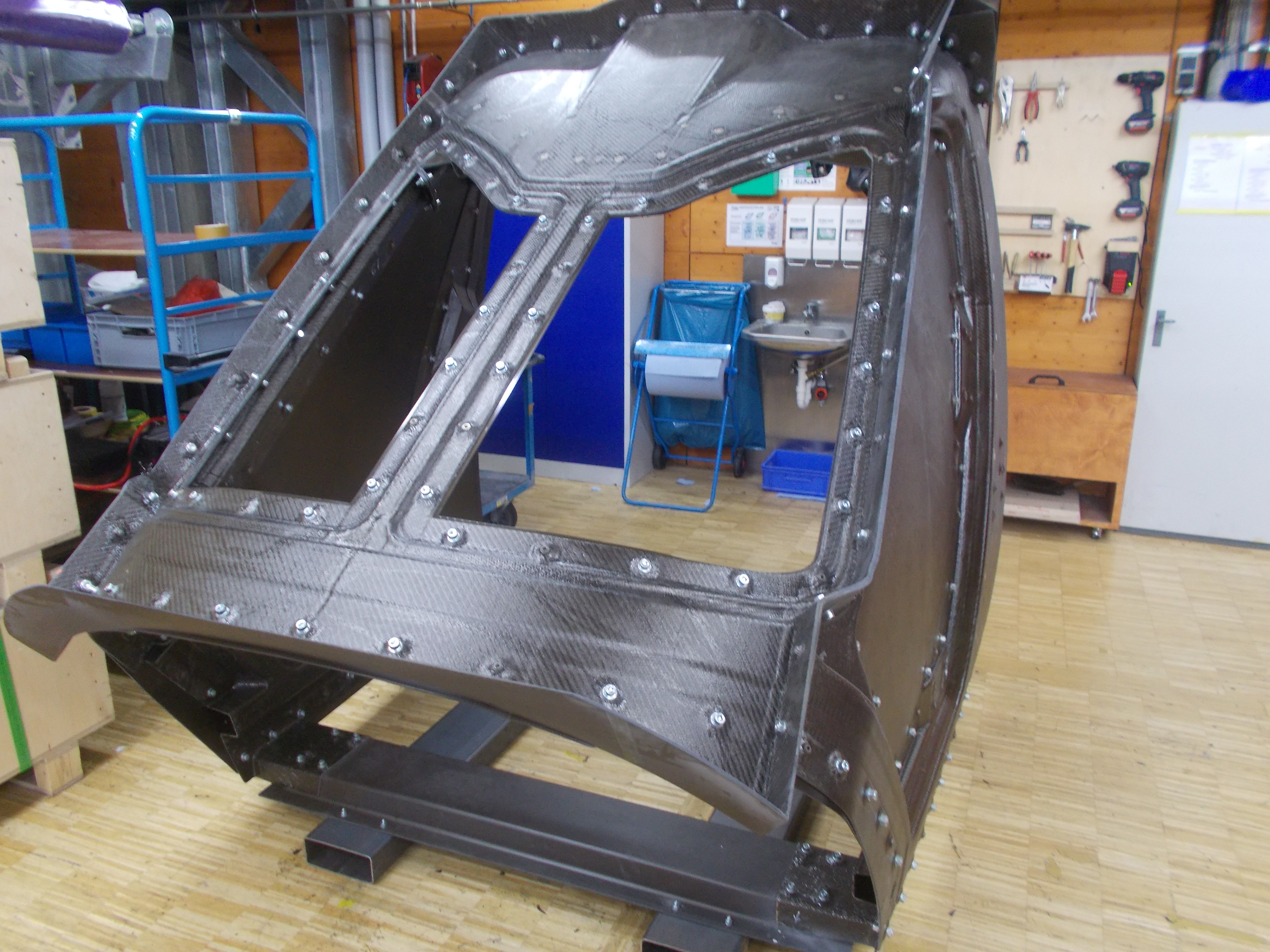
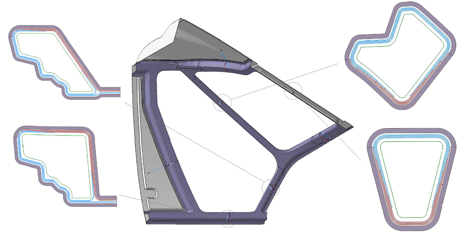
Fig. 2. CFRP canopy tooling
CFRP tooling for the RACER canopy comprises 13 mold segments and helper tools to complete the lamination against the four-piece OML tool (top). Each cutaway of the hollow section layups (bottom) shows two molds joined (thick gray lines) with separate mold layups (blue and pink) and an inner vacuum bag (green). Fiber orientation and staggering of the plies are matched as the two molds and layups are joined. Photo credit: Gerg M&F, KLK Motorsport
For the RACER nose shell and canopy tooling, Gerg M&F created a pattern from RAKU TOOL epoxy board (RAMPF, Grafenberg, Germany) and applied carbon fiber/epoxy prepreg from CIT (Legnano, Italy) to mold CFRP tools for the canopy, nose shell and avionics support. The tools were cured at 55°C and post-cured to enable autoclave curing of the final CFRP parts at 180°C. The tooling was then put through the companies’ measuring protocol, which ensures dimensions and tolerances. For the canopy, four outer molds were mechanically fastened together to form the outer mold line (OML) as a single tool (Fig. 2) while 13 molds were used to create the various hollow, monolithic and cored layups on the inside. “It’s easy to assemble all of these tooling parts, but the inner has to be fitted in a certain sequence,” says Krause. “One cannot be placed before another is mounted. So, these 13 segments from the inside were added step by step during the layup process.”
To laminate these inner parts of the canopy, Krause explains, “they have to be laminated in separate molds. The mold with the layup on it gets assembled with the next mold and then both laminates have to join. And when the molds are joining, the laminates from both molds have to match, including staggering of the plies [Fig. 2]. Therefore, you need helper tools to generate these overlaps.” (An example of a helper tool can be seen in the third layup step in Fig. 3). Stark explains there is just one possible sequence of assembling these molds and their layups for final curing. “What we have learned from motorsport is that every ply overlaps on only one of its counterparts as the layups come together and matches to its adjoining counterpart for fiber orientation and layup sequence, which reduces weight. Also, if the ply staggering is designed correctly, the structural behavior is more continuous and thus stronger.”
“In motorsport in general, we have an even higher degree of integration and more complexity in the parts,” notes Krause. “For example, compared to a CFRP gearbox casing, these parts are really simple.” That may be, but the documentation for all of the canopy tooling and layups comprised 10 plybooks with a total of 350 pages. “For each single ply we have section drawings, we have CSV data for cutting the supplies and a step-by-step sequence book for helping the layup technicians,” says Stark. The nose shell and radome each had one plybook with 77 and 73 pages, respectively.
Manufacturing: First part success
Lamination started on Feb 18, 2020. “We had 15 days to apply the prepreg and get it into the autoclave,” says Stark. “We had a very accurate plan when each ply had to be finished and when all the lamination and vacuum bagging had to be completed, not to exceed the material out-life.” Fig. 3 shows the outer molds of the canopy with one ply already placed. “We don’t use laser projection and we didn’t for this project,” notes Stark. Krause asserts it’s not really needed because the geometry of the part has plenty of geometrical references in the mold. “It’s not so much an issue to locate and apply the plies,” he says, which are cut using a Bullmer (Mehrstetten, Germany) CNC cutter and designed to fit perfectly into the locating geometrical features. “Most of the time, there are edges that reference the position,” he adds. “We don’t have many plies that are somewhere in the middle of a plane area.” He concedes that this layup is highly complex in terms of prepreg production, “but our workforce is trained to a different level than the average laminators.” Stark agrees, “this is what we usually do in every project that we’re working on. That’s maybe new for the aerospace industry, but for us it’s standard. Motorsport typically has parts which are even more complex.”
Most of the parts comprised six full plies with up to 24 additional plies in specific areas for local reinforcement. Prepreg plies were vacuum debulked on the first, third and final plies. “We debulk more often than Airbus does on their parts,” notes Stark, “and that’s also very time-consuming, but it has to be done to make the best quality of the laminate.”
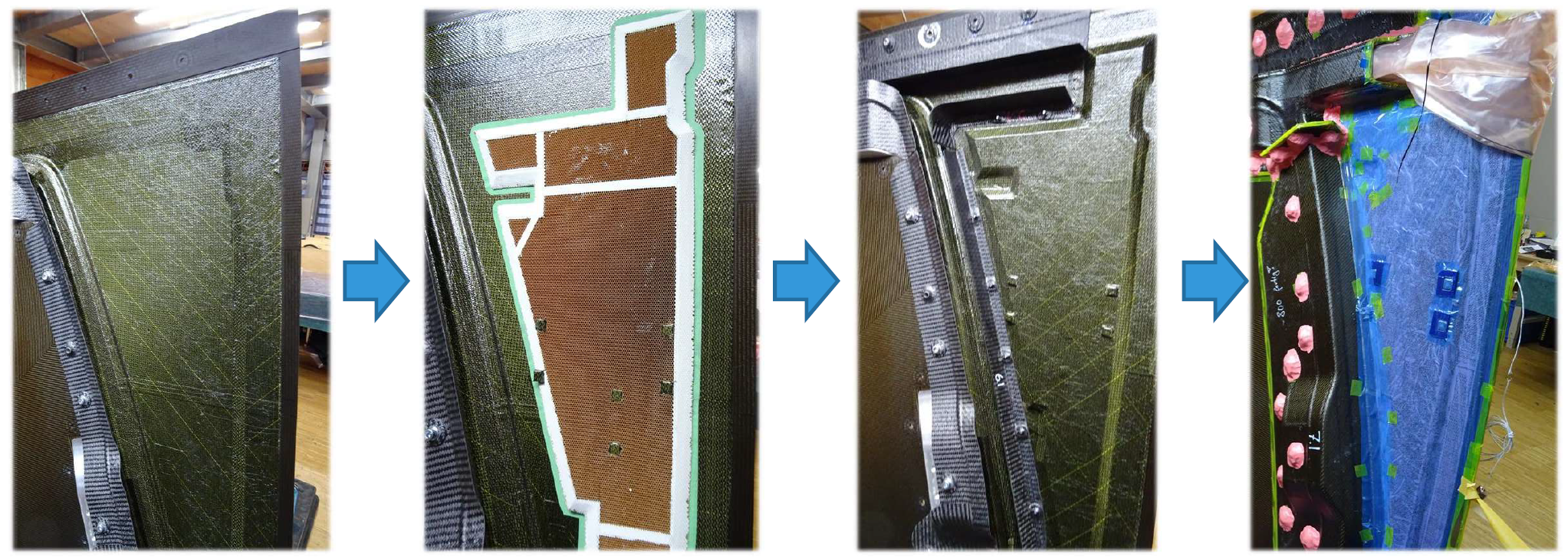
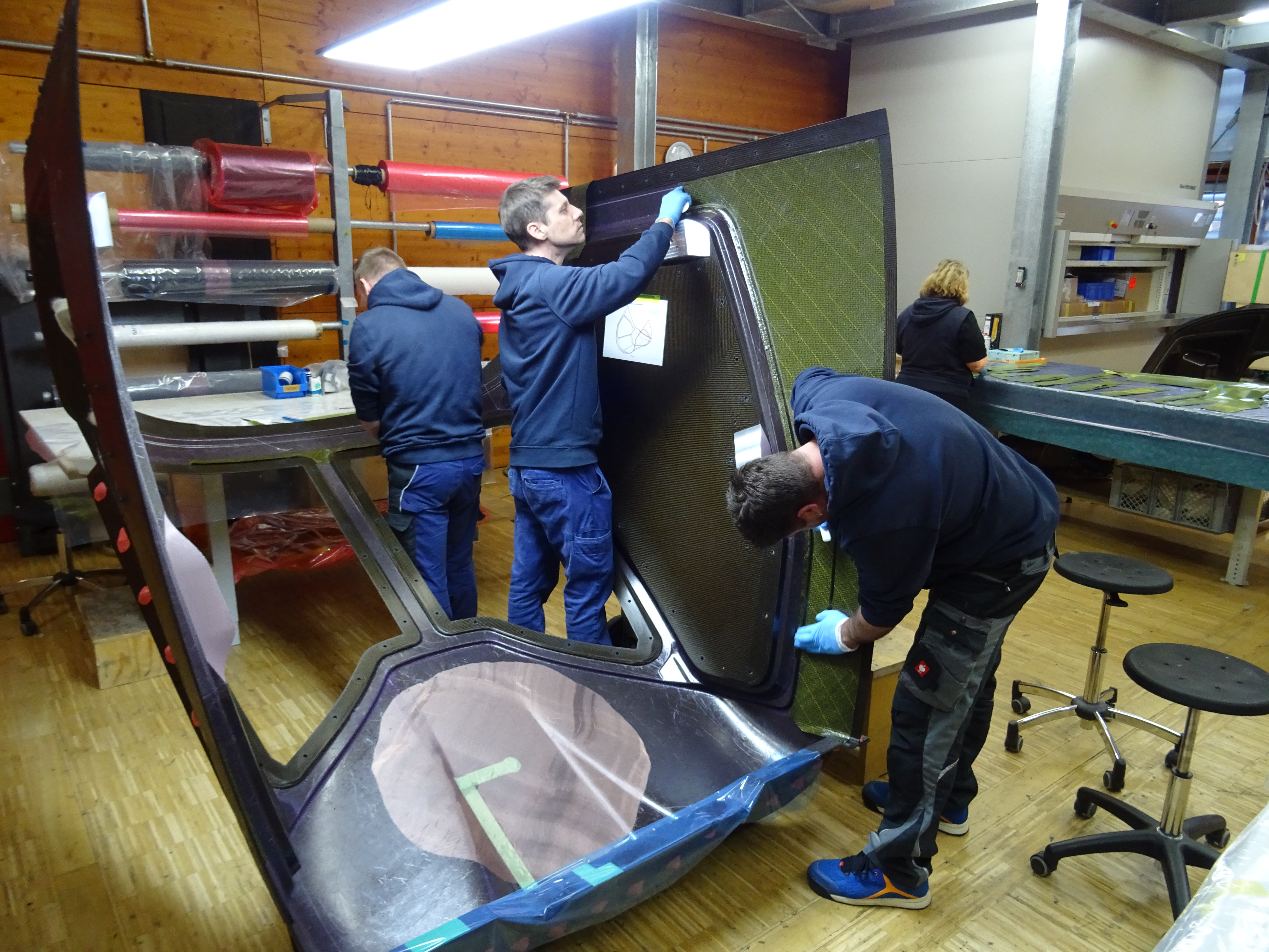
Fig. 3. Canopy layup
The FastCan team laminates one of the canopy sideshells, applying (top, from left to right): outer skin plies, honeycomb core, inner skin plies and assembled molds and vacuum bagging. Photo Credit: Gerg M&F
Lamination steps for one of the canopy side shells are shown in Fig. 3. Stark narrates: “The first skin is laid and then the honeycomb. After the honeycomb, you see in the third step the top skin of the sandwich has been laid and helping tools have been fastened on top. These are there to help laminate freestanding plies that will then be mated to plies on adjoining inner tools, which you can see in the final picture on the right.” That final image also shows the pinkish/orange internal vacuum bag inserted inside of the hollow beam at the top right. Stark refers to them as “blow bags.” “You call them an internal bag,” he says, “but it’s just the normal vacuum bag, but with enough material and fitted so that it’s not shrinking but expanding to compact the inside of the hollow structure. It has its own vacuum line and there are many fittings between this bag and the autoclave.” Stark points out it was a 1.5-day workflow for technicians to apply all of the fittings and complete the vacuum bagging of the whole canopy, including thermocouples.
“We wanted to have fewer parts,” says Krause, “but we were limited in some ways due to the material out-life, because it’s a lot of work to apply so many plies in such an accurate way.” The result was two exhausting weeks for four to six technicians, but the fully vacuum-bagged layup was in the autoclave on March 3, with one day of out-life to spare. “We don’t have such a big autoclave,” adds Stark, “so we transported the bagged layup two hours by car to Donauwörth, Germany, where Airbus Helicopters has a sufficiently large autoclave.” The canopy was then cured at 180°C and 2 bar for three hours.
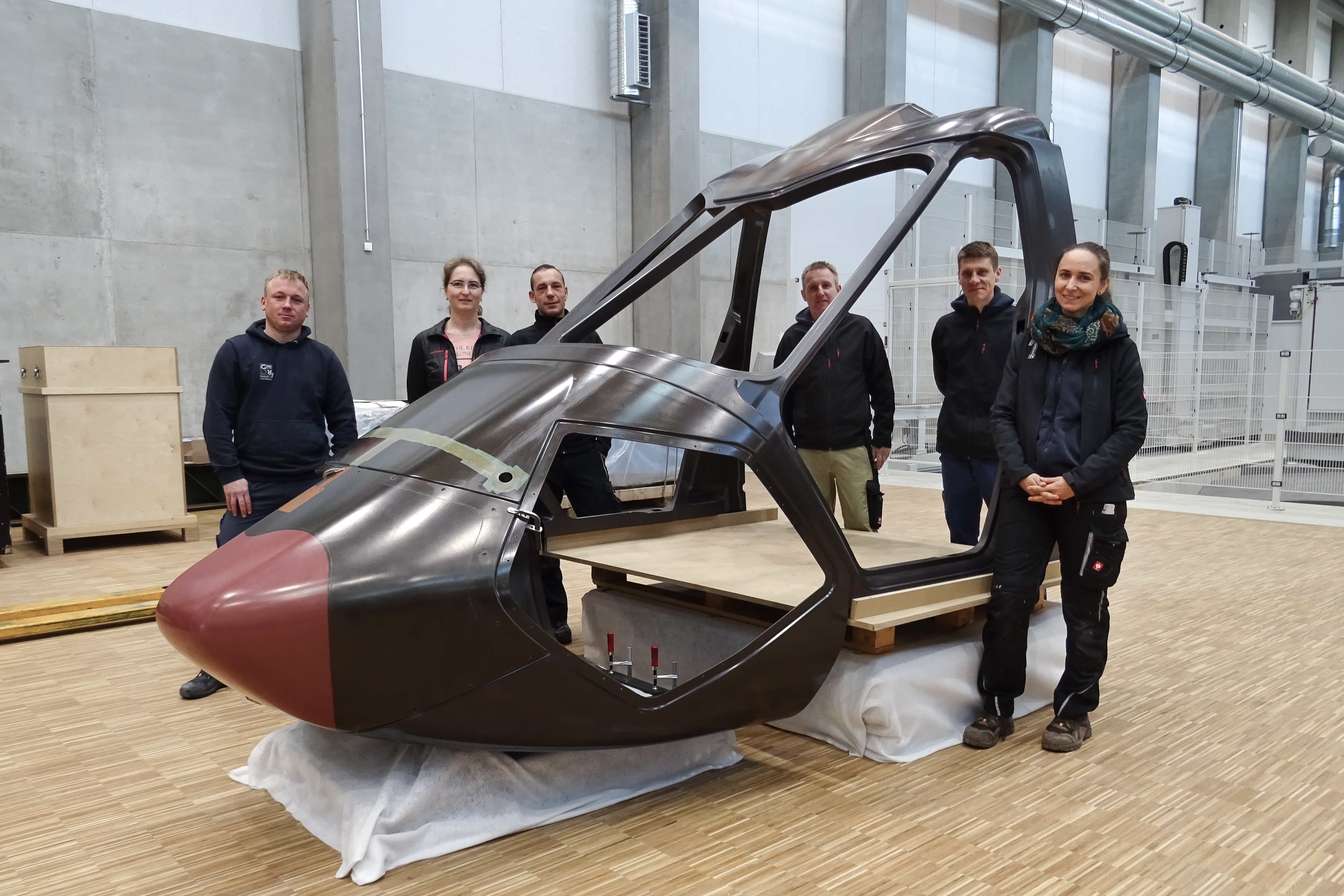
Fig. 4. FastCan success
The flightworthy CFRP forward fuselage for the RACER demonstrator, including first-time-right out of the mold canopy. Photo credit: Gerg M&F, Clean Sky 2 FASTCAN consortium
The 180°C cure cycle was also a challenge. Tooling, internal baggings and joints between bags are much more forgiving at the 120°C cure typically used in motorsport, says Krause. “If there's a little bit of tension somewhere in a corner, you may get away with it. But at 180°C cure, the bag would split. So, the team had to work super accurately to avoid bursting the bag.” Stark adds that the exothermic reaction of the epoxy resin was also an issue, but with the radome. “Because it’s eight millimeters thick, it got overheated. We trashed two radome parts, but all of the other parts came out right the first time.” This first part success with the canopy was especially a triumph. “You never know when you make prototyping if the first part out of the mold will be successful,” says Stark. “The first canopy is actually the flying part.”
Assembly, flight testing and future developments
After all of the parts were cured and demolded, they were measured for accuracy, machined and assembled. “We then painted the whole forward fuselage, mainly with primer, but also a black color on the window edges,” says Stark, “and prepared it for transport to Donauwörth.” RACER’s first phase of assembly began in 2021, including installation of the canopy, box-wings, fuel system, cowlings and several other components into the central fuselage. The fuselage was transferred in August 2021 to Airbus Helicopters’ site in Marignane, France for final assembly and subsequent flight testing in 2022. RACER’s 200-hour flight demonstration will assess key performance objectives including speed, handling, stability and aerodynamics. It will also aim to demonstrate RACER’s suitability to carry out missions and low-noise flight.
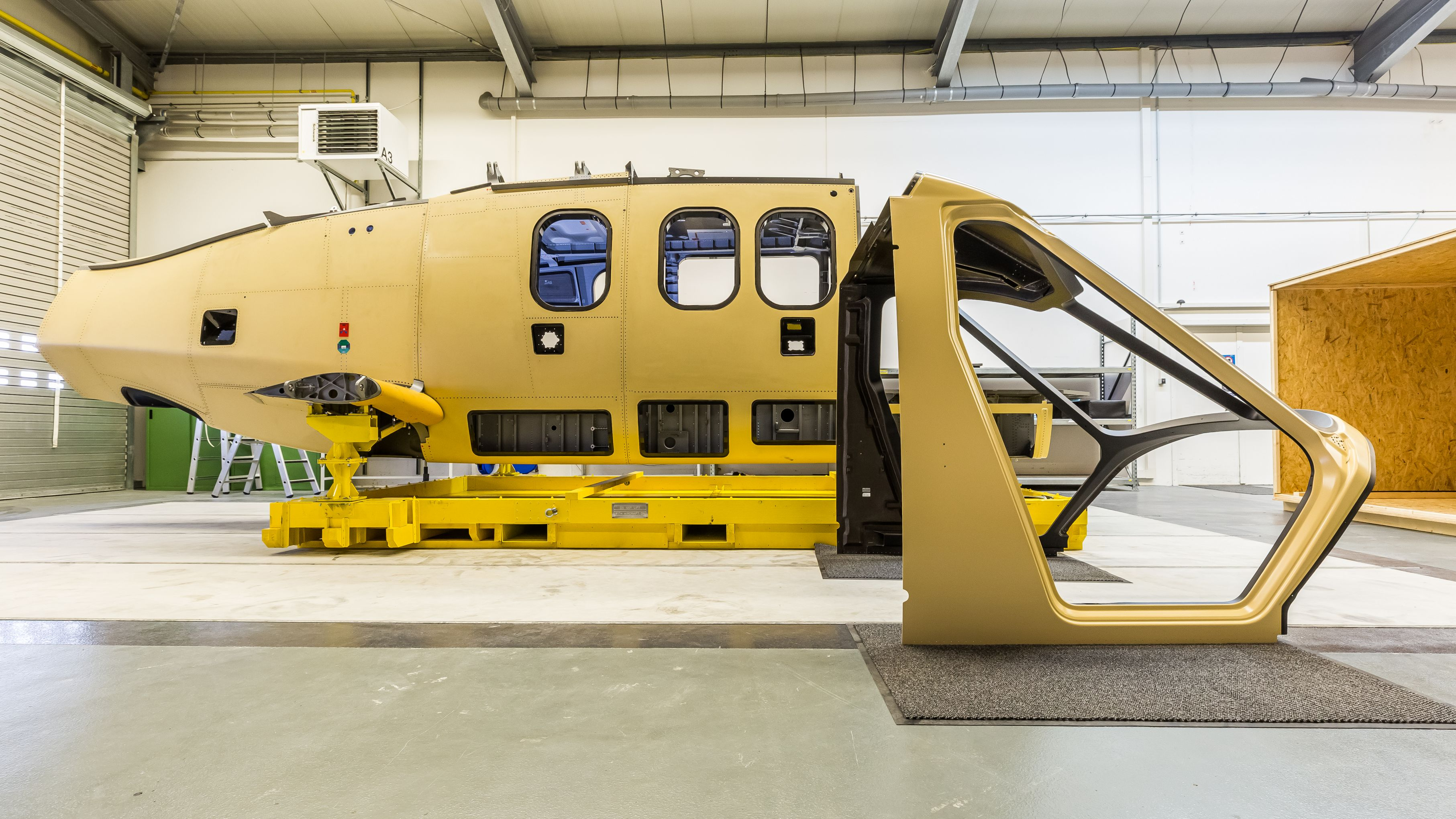
Fig. 5. RACER canopy, primed and ready to be assembled with central fuselage (background), also made from composites. Photo Credit: Airbus Helicopters
“Airbus was very happy with what we achieved,” says Stark. “For Gerg M&F, this was one of our first projects with flying parts. It has opened the door for us, including projects with Boeing and other companies.” KLK, meanwhile, is supporting eVTOL projects. “We are working with first concepts to propose the architecture and complete airframe design and simulation,” says Krause. “We have a large material library from motorsport and we can also do specific material qualifications.”
Part of the vision with FastCan and the RACER canopy was to develop and exploit synergies between the automotive/motorsport and aerospace industries. Has this been achieved? “The degree of integration we achieved is higher than the original design,” says Krause, “and this, in turn, achieves higher weight savings.” Stark says the canopy showed that high complexity is possible. “Maybe it’s more work in the manufacturing, but by saving interfaces and eliminating rivets, we saved cost and weight.” Krause says reductions of 5-10% are possible for weight and 10% for cost versus the original RACER forward fuselage design. He also notes that the complete development and build pace for motorsport is much faster than in aerospace. That pace, adds Stark, is a strength. “I think FastCan has demonstrated that we can deliver aerospace quality and safety and manage multifunctional complexity to achieve new levels of performance at a reduced cost.”


Related Content

Airbus to design, build ESA ExoMars rover lander platform
The resurrected Rosalind Franklin composite rover mission’s key systems will be upgraded with support from the TAS, ESA and NASA for a planned launch in 2028.
Read More
Guidance for the thermoforming process
A briefing on some of the common foam core material types, forming methods and tooling requirements.
Read More
Bio-based, fire-resistant composites become mainstream
Projects use Duplicor prepreg panels with highest Euroclass B fire performance without fire retardants for reduced weight, CO2 footprint in sustainable yet affordable roofs, high-rise façades and modular housing.
Read More
PUR composite sandwich panels for 3D automotive parts, high-volume panels and more
At its U.S. sites, Ascorium produces glass fiber/PUR 3D parts via semi-automated molding, high-volume flat panels via a continuous line while working toward bio-based PUR and recycling.
Read MoreRead Next

Clean Sky 2 FRAMES project advances heating simulation of thermoplastic composite AFP with xenon flashlamp
Heraeus Noblelight and Compositadour develop heating simulation to optimize process temperatures during automated fiber placement of composite aerostructures.
Read More
More Affordable Small Aircraft Manufacturing project in Clean Sky 2 replaces metal nacelle with composites
SAT-AM project composite nacelle reduced component weight by at least 10%, reduced the number of elements by more than 35%, resulted in a more uniform structure and reached TRL 6.
Read More
Scaling up, optimizing the flax fiber composite camper
Greenlander’s Sherpa RV cab, which is largely constructed from flax fiber/bio-epoxy sandwich panels, nears commercial production readiness and next-generation scale-up.
Read More