
Flexural testing of composite materials
Dr. Donald F. Adams (Wyoming Test Fixtures (Salt Lake City, Utah) takes look at flexural testing and promises recommendations, next time, for a unified standard.
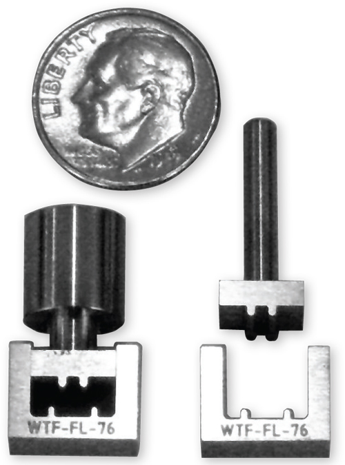
Fig. 1: A miniature four-point loading test fixture with radiused supports. Source: Don Adams
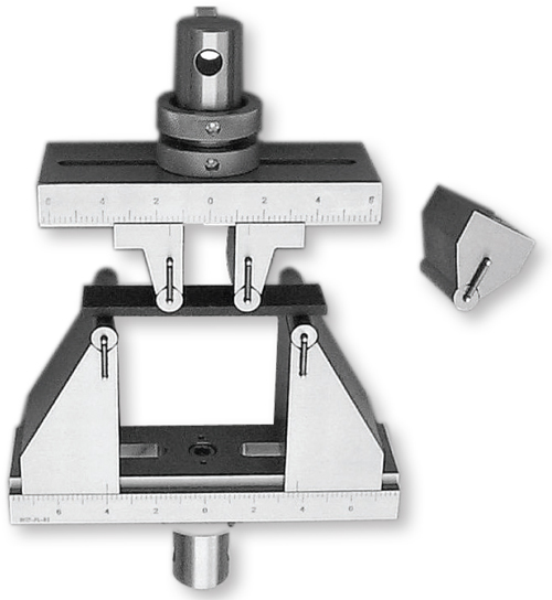
Fig. 2: A flexure fixture with loading/support cylinders supported in V-grooves. Source: Don Adams
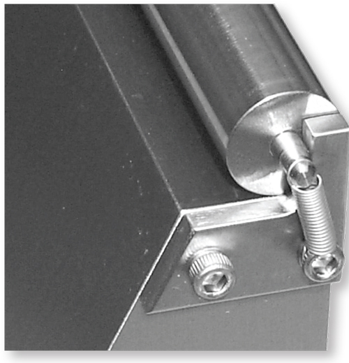
Fig. 3: An example of a rolling support. Source: Don Adams


Flexural strength and stiffness are not basic material properties. They are the combined effects of a material’s basic tensile, compressive and shear properties. That is, when a flexural loading is applied to a specimen, all three of the material’s basic stress states are induced. Material failure, then, is dictated by which of the three basic stresses is the first to reach its limiting value — that is, its strength. Despite the obvious complexities implied by the above, flexural testing is common, the test specimen is easy to prepare, the fixture can be simple and the test itself is easy to perform.
To simplify the stress state in the specimen, it is customary to minimize the shear stress component. This is done by making the specimen support span (ℓ) long relative to the specimen thickness (t), because shear stress is independent of specimen length while the bending moment (and thus the tensile and compressive stress) is directly proportional to specimen length. Today, ℓ/t ratios of 16:1 and 32:1 are commonly used, but ratios of 40:1 and even 64:1 are sometimes specified. At any of these ratios, it is highly unlikely that the specimen will fail in shear.


Normally, the specimen is loaded while in a horizontal position, and in such a way that the compressive stress occurs in the upper portion and the tensile stress occurs in the lower portion of the cross section. If the specimen is symmetrical about the midplane of its cross section (e.g., rectangular), the maximum tensile and compressive stresses will be equal. Thus, whether the specimen fails in tension or compression simply depends on which strength value is lower. For most, but not all, composites, the compressive strength is lower, and thus the specimen will fail at the compression surface. Typically, this compressive failure is associated with the local buckling (microbuckling) of individual fibers.
Both three-point and four-point loading configurations are used. Three-point loading consists of a support point near each end of the beam and one load point at the midspan. For four-point loading, there are two load points at equal distances from the support points. This distance is typically one-fourth of the span length (thus, the term quarter-point four-point loading), but a distance of one-third of the span length (third-point four-point loading) is sometimes used. Relatively little difference in test results has been demonstrated between three-point and four-point loading, so the choice between the two typically is one of personal preference.
Because it is usually desirable to test at a specific ℓ/t ratio, a general-purpose flexure test fixture has to have adjustable support and loading spans to accommodate specimens of various thicknesses. A fixed-span fixture (see example in Fig. 1) is thus limited to specimens of a specific thickness if a specific ℓ/t ratio is to be adhered to. Note that the fixture in Fig. 1 has radiused supports and loading points. When the specimen is loaded, the bottom surface is in tension, and thus becomes longer, causing the specimen to slide on the two supports. The frictional forces generated at the bottom surface are directed toward the midspan, so as the specimen deflects downward these frictional forces add to the bending of the specimen. This typically has a small effect, but can be of concern, as can the wear on the test fixture when the specimen slides. Thus, test fixtures that have radiused supports, such as the fixture in Fig. 1, typically see special or limited use.
The common alternative to a fixture with radiused supports is to support a cylinder in a V-groove. Although friction between the cylinder and the V-groove usually prevents the cylinder from rotating as the specimen is loaded, the cylinder can be made of much harder material than the remainder of the test fixture to resist wear. Also, if the cylinder is not permanently attached but instead held in place by springs or other removable restraints, the cylinder can be rotated to a fresh contact surface if it shows signs of wear. Fig. 2 shows a fixture with removable cylinders. An added benefit is that cylinders of other diameters can be used, although this is limited by the size of the V-groove. Although one can mount the cylinder ends in ball or roller bearings, the latter tend to be bulky and have limited load capacity, so they also find only special use.
A more practical approach is to use rolling supports (Fig. 3). These roll outward as the specimen deflects and the loading rollers roll inward. Although this changes the loading and support span lengths slightly, the change is typically small and, thus, usually ignored. The rolling supports eliminate sliding friction and reduce wear. And if the initial position of the roller is dictated by indexing an axle of fixed diameter against a stop (as in Fig. 3) rather than indexing the roller itself against the stop, an important secondary advantage is that rollers of a relatively large range of diameters can be used with the same fixture, without affecting the support (and loading) span scales that are typically engraved on the test fixture. Perhaps greater use will be made of rolling supports in the future.
Typically, all three or four loading/support points lie in the same horizontal plane. Thus, if the specimen has any twist along its length, or has top and bottom surfaces that are otherwise not flat and parallel to each other, it will not rest uniformly on the contact surfaces. For flexible materials, this is not a significant problem because as soon as the load is applied, the specimen readily conforms to the supports, and in doing so, induces minimal extraneous stresses. For rigid materials, however, this might not be true. In such cases, articulated test fixtures are used. All but one of the support/loading cylinders is free to pivot in the vertical plane across the width of the specimen, thus conforming to the slope of the specimen at that location.
Given this variety of flexural test configurations, it is unfortunate that more logical selections for their use have not been made over the years. There has been regrettably little coordination between the various flexural test standards. Next time, I will survey the standards and suggest how they could be unified.


Related Content

Active core molding: A new way to make composite parts
Koridion expandable material is combined with induction-heated molds to make high-quality, complex-shaped parts in minutes with 40% less material and 90% less energy, unlocking new possibilities in design and production.
Read More
Proving thermoplastic composites match carbon fiber/epoxy performance in road bikes
CDCQ, LxSim, Addcomp and Argon 18 collaborate to optimize a carbon fiber/PA6 bike seat post, democratizing AFP and demonstrating materials and process for future designs and production.
Read More
Optimized rib-reinforced hollow composites via printed molds
Addyx topology optimization and water-soluble mandrel enables simultaneous rib and skin layup for one-shot, high-strength, lightweight structures.
Read More
Aurora reveals latest SPRINT X-Plane design concept
An Aurora and Boeing team advances its high-speed, vertical lift concept to the preliminary design phase, which features three lift fans, a more refined composite exterior and an uncrewed cockpit.
Read MoreRead Next

Bonded fastening meets the digital factory
Automation and XR tools aim to scale adhesive fastening for composites at next-gen aerospace production rates.
Read More
Kaneka BMI material attains >25% lead time, >20% tool cost reductions in Janicki evaluations
Process evaluations find that novel BMI polymer chemistry addresses longstanding manufacturing challenges of BMI tooling prepregs while maintaining high temperature performance and durability.
Read More
Polestar 5 takes aesthetics and circularity approach to biocomposite seatback design
The 2026 Polestar 5 expands the company’s use of sustainable materials design in the interior, including flax fiber/thermoplastic seatbacks that save 7 kilograms of weight and reduce overall plastics use.
Read More