CFRP camera boom enables safe spill inspection
NONA Composites’ 32m REACH structure meets tight remediation schedule at DoE radioactive waste storage site.
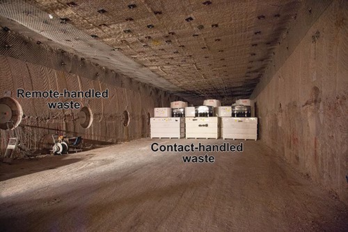
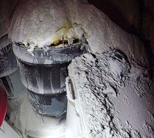
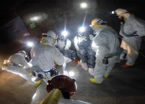
Opened in 1999, 42 km southeast of Carlsbad, NM, US, the US Department of Energy’s (DoE) Waste Isolation Pilot Plant (WIPP) stores clothing, tools, equipment, soils and other materials contaminated by man-made radioactive elements that have been removed from 22 defense-related environmental clean-up sites to date. Kept in disposal rooms carved out of a 762m-thick salt deposit 655m below the earth’s surface, most of the waste (96%) can be contact-handled (CH) by personnel, does not require additional shielding and is stacked in columns within the underground storage cells. The remaining 4% is deposited in chambers bored into the cell walls, requires shielding and is remotely handled (RH) waste — that is, robots and other machinery are used to transport it (photos at left). When a 55-gal drum of CH waste burst in February 2014, a small quantity of radioactive material was released to the surface through the WIPP’s ventilation system. No one was injured, and when all WIPP workers were tested for radiation, none showed exposure levels higher than that of a typical medical X-ray. Nevertheless, the next step was a full investigation of the accident to determine the extent of the damage in the storage room in an effort to re-establish optimal operational safety.
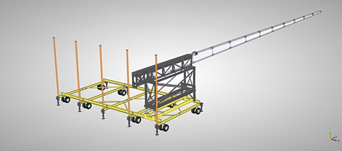
WIPP requested quotes for a steel support structure and cantilevered 27m beam that could deploy a 7-kg sensor package. The system, called REACH, would have to be delivered in pieces that could be assembled underground. Further, the beam would have to be maneuverable, laterally and vertically, around waste containers to facilitate remote video assessment without disturbing post-eruption radioactive particulate that had settled on storage-area surfaces.
Cornerstone Research Group (CRG, Dayton, Ohio) and two Dayton-based subsidiaries, NONA Composites and Advantic LLC, were awarded the beam and sensor package contract on July 21. The REACH system, however, was to be installed and in use before the end of September. Less 10 days for shipping to the WIPP site, that gave the CRG team only eight weeks for design, tooling, fabrication, assembly and shakedown testing.
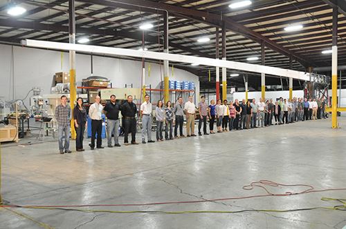
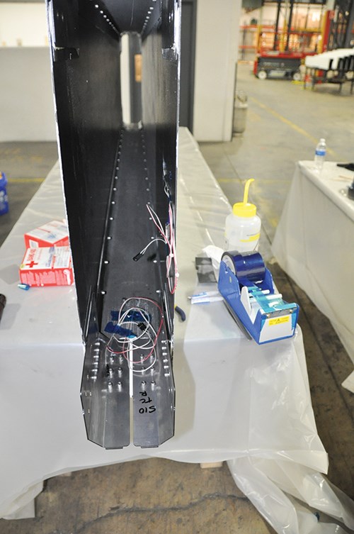
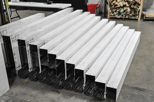
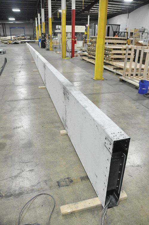
The design and structural engineering was roughed out by Advantic, a CRG spin-off that specializes in advanced composite solutions for the construction and infrastructure markets. “The camera boom had to have a 27m clear reach, but there was also a vertical requirement, in that the boom had only 0.8m of operable space between the ceiling and the top of the waste stack,” explains Advantic VP of engineering Brad Doudican. Therefore, the design was stiffness-driven due to the limited allowable deflection. It also needed to be as light as possible to facilitate mobility and full extension. “We ended up with a box-beam that changes depth continuously along its length,” says Doudican. The width was constant at 152 mm but depth declined from 762 mm at the support to 203 mm at the tip. C-channels would comprise its top and bottom caps, and flat plates would form the sidewalls. The beam was broken down into 12 sections, each 3m long, to make it man-portable and easy to transport via elevator before assembly underground. Section connections would have to be easy to align and attach because assembly would be completed in a high-temperature environment by technicians in full-body protection suits, wearing three layers of gloves.
Design for rapid molding
“Design for manufacturability was our greatest challenge, because we needed to move so quickly,” recalls NONA Composites president Ben Dietsch. “We also sought the greatest flexibility downstream to give us room to refine the structure if needed. This was important because we had to start without a full analysis completed.” This approach permitted the team to initiate the first stages of manufacturing before the structural analyses were in hand.
The big push in the first week was materials selection. “We were limited in what materials we could use because they had to be commercial, off-the-shelf — specifically, available to go on the truck on the afternoon we got the contract,” quips Doudican. This also impacted design. For example, IM7 (from Hexcel, Stamford, CT, US) was not an option for the carbon fiber (CF) because the lead times were too long. “So we started with a rudimentary design using standard-modulus CF to see if it would even work,” says Doudican.
Because the two weeks prior to getting the contract had been spent analyzing all available off-the-shelf tooling and fabrication materials options, the team was able to place orders on day one with suppliers Composites One (Arlington Heights, IL, US) and North American Composites (Hampton, NH, US). “We ended up with a mix of plain-weave carbon fabric, a 12K 2x2 twill and a 24K 630-g/m2 unidirectional broadgood — all standard modulus,” he says.
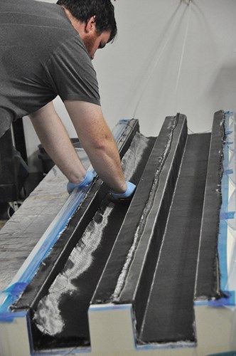
Doudican explains the unis were used on the box beam’s top and bottom, formed by the 6-mm thick C-channels, while the 2-mm thick side plates were shear-driven, and so used the 12K twill. He notes, “All of the parts used plain weave on the outer surfaces to enable good bonded joints and finish coating. Unfortunately, we had to paint it with intumescent paint, so you couldn’t see the carbon fiber surfaces.”
For the resin, the team chose its own No Oven, No Autoclave (NONA) RT-177 two-part epoxy, says Dietsch, “because we had a good knowledge of its processing and it afforded us the short cycle time and fast tooling we needed.” NONA Composites, in fact, was formed by CRG to commercialize it. Matured through NASA-funded SBIR Phase I and II large-structure, carbon fiber-reinforced plastic (CFRP) tooling programs, the resin enables production of tooling and parts with operating temperatures of 204°C and 177°C, respectively, with no heat source beyond the resin’s exotherm during cure. “We did evaluate other systems,” he notes, “but the NONA cure cycle was so fast, we didn’t even have to rely on an oven.”
While NONA Composites initiated its tooling and beam manufacturing processes, CRG and Advantic finished a variety of structural analyses, using Dassault Systèmes’ (Velizy-Villacoublay, France) Abaqus finite element analysis (FEA) suite and CATIA for solid modeling. Composite laminate properties were modeled in Helius:CompositePro, which is now Autodesk (San Rafael, CA, US) Simulation Composite Design 2014. “We did a lot of testing to validate the design,” says Dietsch. “This was part of the quality-control process we developed and documented as part of the contract. We did trial panels for laminates, bonded sections and also sections which were bonded and riveted to validate the final assembled structure.”
Fast foam tools, oven-less cure
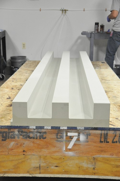
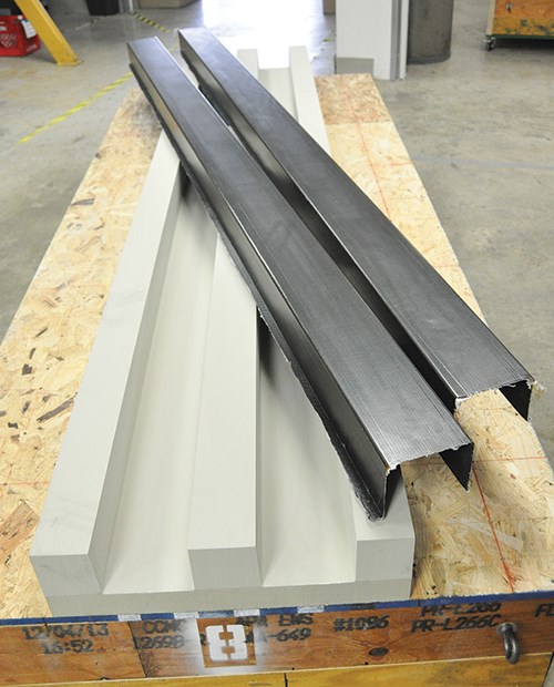
Because NONA’s epoxy infusion resin requires neither autoclave nor oven curing, low-cost tooling (see Step 1, at left) could be machined from high-temperature polyurethane foam supplied by General Plastics Mfg. Co. (Tacoma, WA, US). Two foam grades, FR 4718 and FR 4518, were used because there wasn’t enough of either in stock to meet the project’s total need.
NONA used tools of two types: Two 152 mm wide by 3m long C-channel tools and 1m wide by 3m long flat tools for the progressively smaller side plates, all supported by plywood substructures. “Everything was on wheels for ease of transport and work flow,” notes Dietsch. “We would do layup in one area and then move the tool to the infusion and cure area, some 20 to 30 yards away.” Fabrication of all 14 tools took slightly more than seven days. To save time, each tool was integrated into production as soon as it was finished.
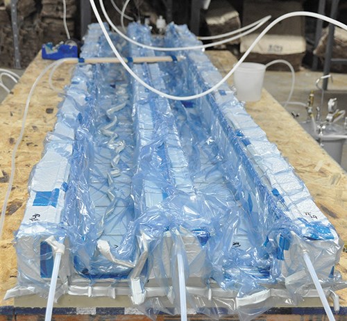
“We could infuse up to four parts at one time, so one team was laying up C-channels and side plates while another was infusing,” Dietsch details. “We infused most of the parts within 35 to 40 minutes. We typically double-bag for a backup to ensure vacuum integrity and reduce the risk of losing the part.” After parts were infused, they were rolled to the cure area while still in the tools and under vacuum. “We kept each part under vacuum in the second bag during the whole cure.”
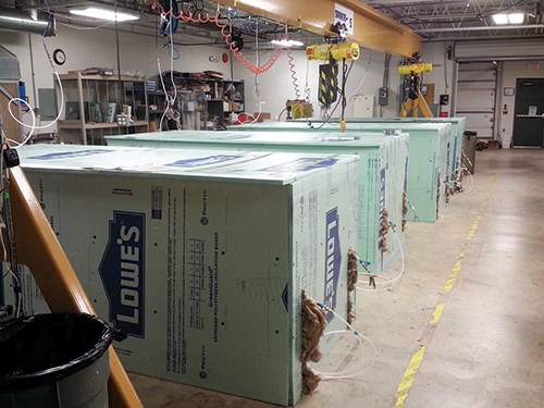
Insulation boxes, made from hardware-store rigid foam insulation board and fiberglass insulation, were then lowered over each tool to contain the heat generated during exotherm (Step 4). “We already knew what insulation we needed to reach the temperatures required for full cure,” explains Dietsch. “It only took us a half day to build all of the insulated boxes. We couldn’t have found an oven big enough to cure the parts in the time we had, nor did we have time for a long oven cure cycle.”
As part of the cure regime and quality control (QC) process, part temperatures were monitored by thermocouples installed across the part. All parts had to meet a minimum temperature requirement yet remain under a maximum allowable peak temperature, but Dietsch claims that the resin chemistry’s design is such that “you don’t need the temperature-control software used with traditional epoxy processing.” The user can determine when the peak exotherm will occur based on the part thickness and type of tooling used. “You don’t have to adjust any catalysts or accelerators,” he points out.
For this project, the laminates reached peak temperature within two hours, followed by a cool-down period of four hours. Despite the resin predictability and the simplicity of the insulation-box technique, Dietsch concedes, “We could still have had issues with temperature consistency across the part. But the past five years have helped us to understand the heat and energy balance.” The team, therefore, achieved a part yield of more than 90% (less than 10% scrap) over the whole project and recorded the fastest timeline, to date, for NONA Composites-built parts.
Ensuring accurate assembly
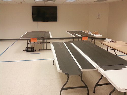
All of the composite parts were laminated within a couple of weeks. It took roughly two more weeks for postmold processing of the demolded parts and then assembly of the box beam sections (Step 5). Trimming and machining were partly done in-house and partly subcontracted. “Waterjet cutting of the flat panels was so much faster than machining in-house,” Dietsch recalls. “We could do one run per day for a couple of days and it was all done.” The channel trimming, however, took more setup. So, the team did that in-house using custom-built jigs.
The C-channel and side-plate surfaces were then prepared for bonding. Lord Corp.’s (Cary, NC, US) 7545 acrylic adhesive was filled with glass microbeads to help maintain a constant bondline thickness. “We chose this because it had a short setup time — specifically, within a couple of hours vs. 24 hours for other systems,” recalls Dietsch. “We couldn’t handle that much delay in the overall timeline.”
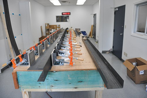
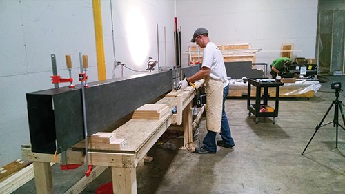
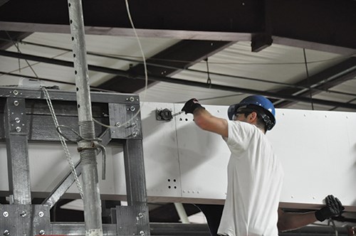
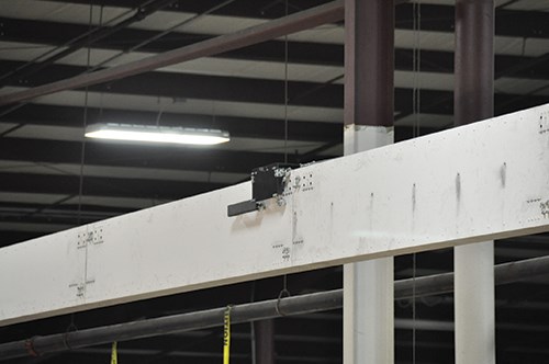
The completed box beam sections were assembled using a joint system that incorporated steel connection plates and high-tolerance shear pins and rivets, for which holes had to be machined (Step 6). “We had to create a fairly complicated assembly jig that could mate two bonded beam sections simultaneously in order to make sure each section was aligned perfectly,” Doudican explains (Step 7). “We could not afford a few inches of vertical deflection in the final assembled beam due to loose assembly tolerances.”
After bonding, dry fitting and machining of holes in the custom jigs, the nine box- beam sections were mechanically fastened to form the 32m structure (Step 8).
By week six, the REACH system had been assembled and tested. “This dry run had to be completed before anything could be shipped,” says Dietsch.
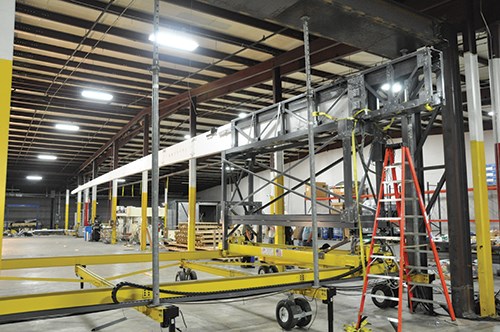
While the CFRP beam was in progress, a parallel effort was mounted to design the system that would move the assembled beam and a small Mars Rover-type sensor caddy that would transport a camera and sensors along the beam, including the electronics and control software. A composite beam cradle and support frame was designed and fabricated using pultruded Extren Shapes from Strongwell Composites (Bristol, VA, US). Testing of these systems together with the beam was completed with one week to spare.
“So the project took seven weeks total,” says CRG CEO Patrick Hood, “but two of those were final testing and system shakedown. The system was deployed at least six times, with less than 1 mm deflection at the support side. We utilized actuated tilt devices within the support structure, which allowed us to be well within our 762-mm deflection limit under load.” Doudican points out that some of the observed deflection was caused not by changes in the composite beam, but rather by thermal expansion of the steel in the lateral motion system during daily temperature cycles.
The beam was assembled and deployed for training at WIPP in September and was used to survey the potentially contaminated areas during the next few months.
Planning pays off
“We’re very proud of what our team accomplished in such a short span of time,” says Dietsch. “This was a highly orchestrated dance between structural, mechanical and electrical design, procurement, fabrication and validation accomplished in a highly integrated process — all happening simultaneously.” Its success, he says, was in large part due to the energy and effort spent in planning, but adds, “The speed and ease of using NONA afforded us a great deal of that time."
Related Content
Filament winding increases access to high-performance composite prostheses
Steptics industrializes production of CFRP prostheses, enabling hundreds of parts/day and 50% lower cost.
Read MoreKorean researchers develop 3D printed CNT sensors for health monitoring, flexible electronics and smart textiles
CNT-based nanocomposites are optimized specifically for vat photopolymerization-type 3D printing, maintaining high stretchability and electrical conductivity.
Read MoreJames Cropper Optiveil polyester veils pass key medical standards
New opportunities in healthcare are unlocked with the surface veil technology’s validation for use in sensitive medical environments.
Read MoreGenerative Orthoses project to reshape orthopedic care
CRP Technology, MHOX and Istituto Ortopedico Rizzoli, one of the winners of the WORTH Partnership Project II, have developed bespoke orthoses using generative design, Windform GT fiberglass materials and PBF.
Read MoreRead Next
Cutting 100 pounds, certification time for the X-59 nose cone
Swift Engineering used HyperX software to remove 100 pounds from 38-foot graphite/epoxy cored nose cone for X-59 supersonic aircraft.
Read MoreScaling up, optimizing the flax fiber composite camper
Greenlander’s Sherpa RV cab, which is largely constructed from flax fiber/bio-epoxy sandwich panels, nears commercial production readiness and next-generation scale-up.
Read MoreUltrasonic welding for in-space manufacturing of CFRTP
Agile Ultrasonics and NASA trial robotic-compatible carbon fiber-reinforced thermoplastic ultrasonic welding technology for space structures.
Read More

