
Carbon fiber: Key to cost-conscious rehab
Carbon composites are effective solutions for repairs and upgrades of reinforced concrete.

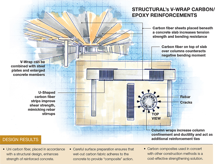
Structural's V-Wrap Carbon Fiber Reinforcements. Illustration: Karl Reque

When Courthouse Square (Salem, Ore.) was in need of repair and strengthening, to address design and construction errors, V-Wrap carbon was part of the solution. Source: Structural
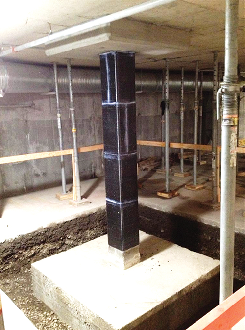
The V-Wrap on this column in the Salem parking garage was combined with a bigger column footer and a cast-in-place capital (square casting around column top) that increases punching shear capacity. Source: Structural
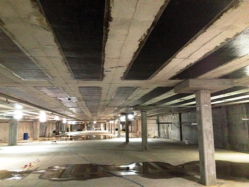
Structural reports that V-Wrap composite sheeting can be to a concrete slab at a fraction of the cost of new construction. Source: Structural
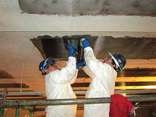
Workers apply V-Wrap composite sheeting to a concrete slab. Source: Structural

As an alternative to V-Wrap, Structural sometimes employs near-surface-mount (NSM) carbon fiber composite rods, often in parking garages to address negative bending. More durable in heavy traffic situations, the rods are pultruded by Hughes Brothers Inc. (Seward, Neb.) and range in diameter from 0.375- to 0.50-inch (9.5 mm to 12.5 mm) (roughly equivalent to #7 steel rebar. They are placed in grooves (about 0.75-inch/19 mm wide and at a similar depth) slotted into the concrete surface and affixed with epoxy putty. Source: Structural


Design Results
- Uni carbon fiber, placed in accordance with a structural design, enhances strength of reinforced concrete.
- Careful surface preparation ensures that wet-out carbon fabric adheres to the concrete to provide “composite” action.
- Carbon composites used in concert with other construction methods is a cost-effective strengthening solution.


Steel-reinforced concrete is among the most widely used building materials in the world, but it faces potential threats, including damage from seismic events, and cracking due to temperature-related expansion and contraction. The latter is common, and permits moisture invasion, and the resulting corrosion and expansion of steel rebar deteriorates the concrete, resulting eventually in loss of structural capacity. In many cases, distressed structures can be repaired. They also can be strengthened to comply with changes in load demands or code revisions. Further, design or construction deficiencies can be corrected to improve load-bearing capabilities.
Carbon fiber composites play a major role in such repairs and upgrades, and do so at significantly less cost than new construction. According to Jay Thomas, VP of strengthening solutions at Structural (Hanover, Md., a Structural Group company), more than 20 million ft2 (1.85 million m2) of carbon fiber already have been installed in reinforced concrete buildings in the U.S. alone. Structural, in the business for nearly 40 years, comes well-prepared. “We take a lot of factors into account, including constructability, aesthetics and cost, and essentially, reverse engineer the building’s structure to improve performance,” he asserts.
Percentage of ultimate capacity
“Both structural repair and structural strengthening require knowledge of the global behavior of the entire building,” Thomas explains, noting that the task is sometimes complicated by the fact that the engineer has no firsthand knowledge of how the structure was originally designed or built. “A design must be tailored for each specific situation and its load conditions.” To that end, Structural’s engineers first conduct a comprehensive inspection. The structure’s elements are catalogued as to type (e.g., round vs. rectangular columns, slab construction, etc.) and condition, and compared to the original construction drawings, if available. A key step is locating and mapping the reinforcing steel inside the concrete, which is accomplished with ground-penetrating radar (GPR) equipment. Other nondestructive testing methods (e.g., pin testing) are used to measure the concrete’s resistance to penetration. Typically, cores extracted from the concrete are subject to microscopic examination and compressive strength tests in the laboratory. The goal is to identify, quantify and evaluate compression strength problem areas.
The investigative team uses the site inspection data to build a virtual layout of the building, using modeling software developed for repair/strengthening applications. SAP2000 from Computers & Structures Inc. (Walnut Creek, Calif.) is one of several programs used. “What the modeling ultimately helps determine is, can the building withstand the load requirements desired by the customer? Are required upgrades constructable and cost-effective, when compared to replacement?” says Thomas. Answers to these questions help the team develop and cost a specific repair or rehab strategy.
“Carbon fiber is one of several solutions we can implement,” he points out. If the modeling shows that the required actual load demand exceeds the existing capacity by more than 40 percent, the strengthening options must be able to carry significant primary loads. Options include bonded steel plates and enlargement of existing concrete structural members. However, if the increase in load conditions is less than 40 percent, the most cost-effective solution, he contends, is Structural’s trademarked carbon fiber/epoxy V-Wrap material. Made with a proprietary unidirectional fabric of intermediate-modulus carbon fibers supplied by Toray Industries Inc. (Tokyo, Japan, and Decatur, Ala.), the material can be used alone or in combination with the options listed above. Labor costs typically drive strengthening projects, so the cost of the carbon isn’t a factor, Thomas claims, and the relative ease of application can actually help reduce project costs.
“Composite” action
V-Wrap works because it becomes an integral part of a concrete member via bonding, resulting in what Thomas calls “composite” action. The term is a reference to the fact that the carbon/epoxy laminate and the concrete column or slab to which it’s applied act together to bear applied loads. To achieve this effect, however, surface preparation is crucial, Thomas stresses. Grit-blasting and grinding with specialized abrasive disks (with the dust and debris vacuumed away) ensure a clean surface on undamaged concrete. “The concrete is like a big, hard sponge,” he explains. “You’ve got to open the pores and get the resin to fully penetrate to achieve an effective bond.”
Dry V-Wrap fabric sheets are wet-out at the job site, using Structural’s in-house-designed field saturators. (A saturator dips fabric in a resin bath and then passes it through precisely gapped rollers and/or scrapers, to yield a wet layup with a precise — and project-specific — resin content, without air bubbles that could result in voids.)
Where and how V-Wrap is applied is guided by Structural’s extensive experience, the modeling results and, in some cases, limitations imposed by fire codes. As shown in the drawing (top left), V-Wrap material placed beneath a horizontal slab increases its tension strength and bending resistance; strips are placed on the slab’s bottom surface with the fiber direction parallel to the slab’s steel rebar: “The V-Wrap is mimicking the action of the existing reinforcing steel, and augmenting its strength,” he explains.
Fiber sheet placed on a slab’s upper surface — over supporting columns, for example — counteract the slab’s negative bending moment. For additional beam shear capacity, typically where a beam is connected to a column, V-Wrap is applied to the beam in a “U” shape that mimics the beam’s steel shear stirrups. The stirrups and fiber prevent or minimize formation of 45° shear cracks that can occur if the beam/column intersection is overloaded. Finally, carbon fiber is exceptional at increasing confinement and ductility in concrete columns. When wrapped horizontally around the column, the fiber wrap acts as additional reinforcing ties around the column circumference.
Thomas cautions that the effects of strengthening local structural elements must be analyzed carefully to determine their influence on the structure’s global behavior. “Increasing the bending capacity of a structural element may overstress it in shear or, possibly, affect the surrounding elements, and lead to even bigger problems or even localized failure,” Thomas notes, pointing out that carbon fiber’s effectiveness depends on the original stiffness of the structural element to which it is applied. “Flexural strengthening is most effective on concrete members that were originally lightly or moderately reinforced,” he explains. Adding carbon fiber to an already very stiff element doesn’t contribute much, because the element must deflect to engage the bonded fiber. Structural follows guidance from the American Concrete Institute’s ACI 440.2R-08, Guide for the Design and Construction of Externally Bonded FRP Strengthening Systems for Strengthening Concrete Structures (2008), which, in essence, discourages the use of excessive FRP. “Full-scale testing has shown that more is not better,” he notes. “Too many plies create stresses that exceed the concrete’s tensile capacity and can actually cause the FRP to fail by peeling it away from the concrete under high loads.
To ensure that the upgraded structure will perform in service as predicted, load tests, both cyclic and monotonic (steadily increasing load), can be performed before and after the strengthening, using hydraulic actuators, to validate that the addition of the carbon fiber has achieved the required increase in capacity. And to verify that V-Wrap is bonded securely, Structural conducts pull-off adhesion tests: “The V-Wrap, per ACI 440, has to pass a 200-psi test,” adds Thomas.
Samples of success
Thomas cites a recent job in Miami, Fla., which involved converting a former shopping mall to a control center for a telecommunications company. A ~25 percent increase in load-carrying capacity was necessary to handle the 150-lb/ft2 (730-kg/m2) loads created by the company’s equipment. The structural floor, a one-way slab, is supported by precast, prestressed joists that rest on continuous cast-in-place concrete beams with precast soffits (soffit, here, is the underside of a beam, in tension). “We selected an approach in which multiple plies of carbon strips were bonded to the sides and bottoms of each joist, to increase bending moment capacity,” explains Thomas. U-wrap strips anchored the longitudinal strips at each end. Beams were strengthened by placing carbon strips on their undersides to increase bending capacity at mid-span, and four U-wraps were applied for shear. V-Wrap sheets also were placed on top of the slab, on each side of, and centered on, column locations to strengthen the beams.
In Salem, Ore., the five-story Courthouse Square complex, built in 2000, housed city government offices, retail outlets, a public transit hub and underground parking. But buckling floor tiles, water seepage, windows that no longer opened and cracking walls forced building closure. Thomas says Structural’s initial inspection identified errors in the structural design and construction mistakes, in columns, shear walls, slabs, footings and masonry cladding.
“The building’s serious flaws demanded a complex combination of repairs, including concrete enlargement, bonded overlays (i.e., adding additional concrete to slabs) and V-Wrap,” Thomas recalls. The parking garage and office space columns were fitted with formwork to create capitals using cast-in-place reinforced concrete, to increase their punching shear capacity (i.e., so that the flat slab would be better supported). V-Wrap came into play as column wraps (see photo, at left).
Structural works on hundreds of projects each year, but Thomas says it’s still a challenge. “Unknowns such as structural conditions and load paths, or the location — or lack of — existing reinforcement,” he says, make each project unique. And as long as there’s concrete, there’ll be work to do.


Related Content

Bcomp, Temca achieve intricate composite cladding for French school façade
A combination of flax and glass fibers went into the development of 880 openwork, shade-providing panels for an international school in France.
Read More
Renco USA brings Lego-style composite building system to construction
After more than a decade dedicated to R&D, evaluation and testing, the company has proven its MCFR building system in a Lakewood Village project in Florida.
Read More
U.S. grant is awarded for patented SIP composites formwork system
ConTech stay-in-place (SIP) technology, made from recycled composite materials, replaces the use of reinforcing steel in the construction of flat, elevated concrete surfaces.
Read More
Composites end markets: Infrastructure and construction (2024)
Composites are increasingly used in applications like building facades, bridges, utility poles, wastewater treatment pipes, repair solutions and more.
Read MoreRead Next

GFRP rebar replaces steel in parking garage
Composite rebar in replacement concrete slab the key in life-extending and less-costly structural rehabilitation project.
Read More
Ultrasonic welding for in-space manufacturing of CFRTP
Agile Ultrasonics and NASA trial robotic-compatible carbon fiber-reinforced thermoplastic ultrasonic welding technology for space structures.
Read More
Ceramic matrix composites: Faster, cheaper, higher temperature
New players proliferate, increasing CMC materials and manufacturing capacity, novel processes and automation to meet demand for higher part volumes and performance.
Read More