
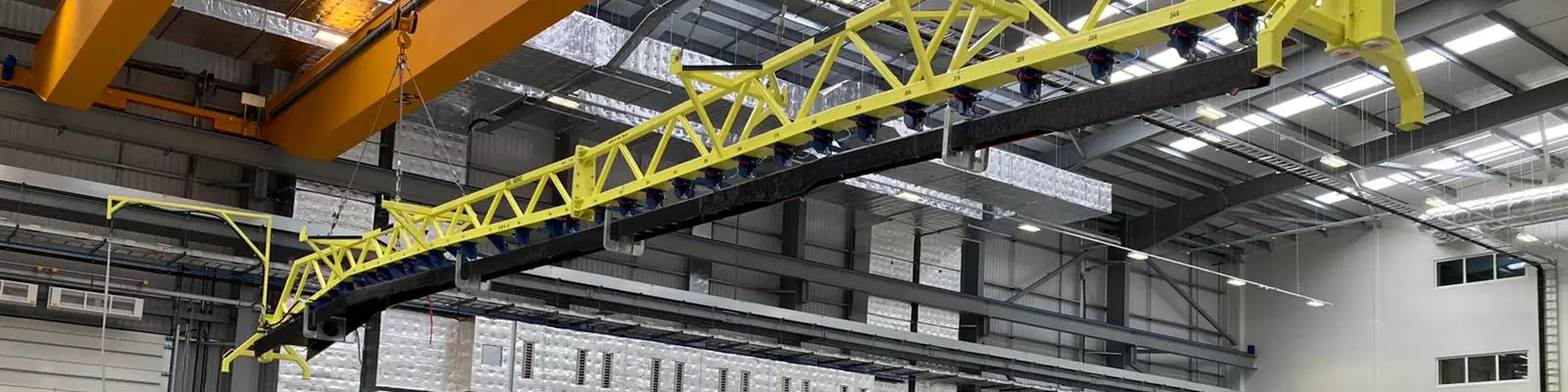


GKN developed semi-automated manufacturing processes for the first WOT spars, with the ultimate goal of almost fully automating fabrication. The spar is fully preformed here and being prepared for transfer to the production tool for resin transfer molding (RTM). Photo Credit, all images: GKN Aerospace
There is, arguably, no single structure in an aircraft wing as complex and difficult to manufacture as the spar. The spar is a long C- or I-shaped primary structure that runs the length of the wing, spanning from root to tip. A wing box, depending on the size and type of the aircraft, might have one or multiple spars. In commercial aircraft, there are typically two spars, one located at the leading edge and the other located at the trailing edge. They attach to the wing skins, ribs, undercarriage structures and flaps and are designed to carry the bending loads in the wing generated by aerodynamic forces acting on it. A spar is almost always tapered — thicker and wider at the root of the wing and thinner and narrower at the tip. In addition, a spar must follow the contour of the wing box and often is angled to accommodate the sweep of the wing.
Airbus (Toulouse, France), when it developed the composites-intensive, twin-aisle A350 aircraft, made the decision to switch to composite materials for the wing skins, stringers and the 34-meter wing spars. The gull-wing shape of the A350 wings dictated integration of two angle changes in the rear spars, so Airbus opted for a design that split the rear spars into three sections, each fabricated using automated fiber placement (AFP) of carbon fiber prepregs on C-shaped mandrels. The spar sections are each just over 11 meters long and, post-autoclave, joined using custom-fabricated CFRP plates to assemble them. This fabrication and assembly work is performed by GKN Aerospace at its Filton, U.K., facility. (Read more about A350 spar fabrication in this CW story, “A350 and A400M wing spars: A study in contrasts”).


However, next-generation commercial aerospace wing structures — particularly those for high-rate aircraft — must and will evolve to a more integrated design that allows airframers to produce co-cured, out-of-autoclave (OOA) structures that can meet demanding performance, cost and production requirements.
Airbus is tackling this challenge with its Wing of Tomorrow (WOT) program. WOT comprises structures from several suppliers, each evaluating different composites M&P strategies. These include, but are not limited to, the infused lower wing skin from Spirit AeroSystems (Wichita, Kan., U.S.), thermoplastic composite ribs from GKN Aerospace (Hoogeveen, Netherlands), and additional thermoplastic ribs and a vacuum bag-only rear spar from Daher (Nantes, France). Also on this list is a 17-meter fixed trailing edge (FTE) assembly development which was awarded to GKN Aerospace in Western Approach, U.K. The most critical part of the FTE that GKN had to develop is the 17-meter, one-piece, resin transfer molded (RTM) trailing edge spar.
The challenge of a long, tapered, RTM’d structure
Gavin Lunney, principal engineer at GKN Aerospace, says the company joined the WOT program in 2017 and was given the interface geometry and the mechanical performance properties of the spar. Beyond that, GKN had much design freedom and, Lunney says, “started from scratch” to develop the structure the company has now produced.
The requirements of GKN’s solution were few, but daunting: The finished full-scale spar, deliverable by 2022, had to be 17 meters long and molded in one piece. Further, GKN had to demonstrate full-rate production capability using cost-effective M&P. Lunney says the project posed a significant challenge when he took it on, but it also seemed very possible.
“For the geometry, I think they’ve taken typical spar geometry and then pushed it to the extreme to challenge us to try and understand the limits of what we can actually manufacture,” Lunney says.
GKN recognized quickly that it would have to take a design-for-manufacture approach to achieve the rate requirements Airbus imposed. To address this challenge, GKN decided to break the spar development project into three phases. The first would work on fabrication and testing of small structures, including flat panels. The second and most intensive phase would work on fabrication of a 5-meter section of the full spar to prove design and manufacturing viability. The third phase would work on fabrication of the full 17-meter spar. In this way, the company would be able to incrementally evaluate M&P performance and adjust as needed before the final build.
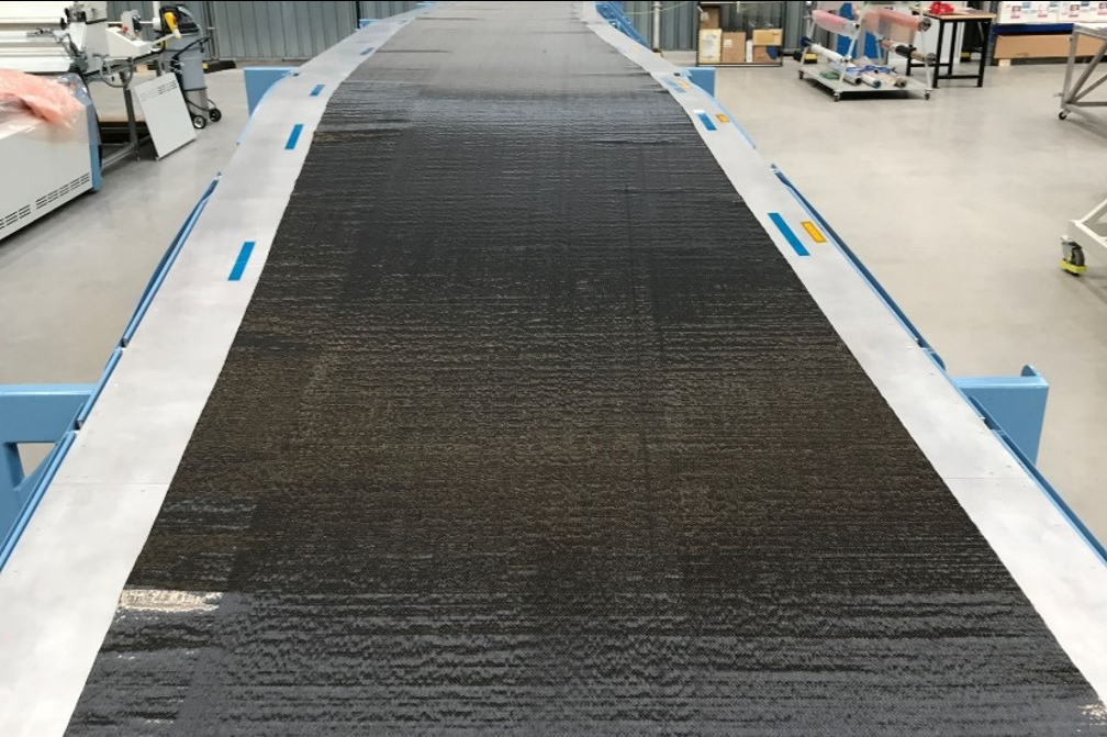
A two-ply carbon fiber noncrimp fabric (NCF) manufactured by Teijin was specified for the spar. Shown here is the NCF kit, after automated cutting and prior to preforming.
“This spar is probably the most demanding spar we’ve ever seen in terms of its kink sweep and its flange angle, so it presents a lot of challenges to the mold tool design,” Craig Carr, technology director integrated composite structures at GKN Aerospace, says. “A lot of those were solved when we went through the mid-scale part of the program, and we were then able to go to the full-scale tool.”
Lunney adds: “And then in parallel, we broke the spar down into a number of discrete features — such as the radii, or the kinks or the thickness transitions — and we focused on understanding if we could develop a process that could accommodate these features.”
The material combination Airbus specified for the spar is a two-ply carbon fiber NCF supplied by Teijin (Tokyo, Japan) that would be infused with Solvay Composite Materials’ (Alpharetta, Ga., U.S.) epoxy resin system. The final spar that GKN ultimately developed uses a C-shape design that has two angle changes — or “kinks” — to accommodate the wing’s sweep.
In the early days of the program, as GKN began work on panels and discrete features, the question arose of how to build the ply architecture for the relatively heavy NCF. Typically, Lunney notes, an NCF placed over a long, non-straight, C-shaped structure with two angle changes and variable thickness requires strategic cutting and darting of the NCF to avoid wrinkling that can degrade strength properties of the structure. However, cutting and darting, for a high-volume aerostructures program, would be inefficient. GKN wanted and needed full-rate production of the spar to be as automated as possible.
Lunney and his team thus decided early on that the 17-meter infused spar could only be viable in a high-rate manufacturing environment with a design that did not require cutting and darting but still avoided fabric wrinkling. Instead, GKN would rely on strategic and careful ply placement that was conducive to automation and produced a finished structure that met Airbus’ mechanical requirements.
“If you do have darts, you have to introduce staggering, joint plates and a whole heap of complexity into your manufacturing process that you really don’t want,” Lunney says. “I think it benefits everybody to not have darts. It’s one piece and one shot, so there are no joints. The zero-degree plies run from root to tip. When we form around the flanges, we don’t dart the material, we don’t do anything. We’re able to shear the NCF so that we have fiber that follows the contours of the part.”
Carr adds: “There’s not an insignificant knockdown factor if you end up putting a lot of darts in a spar. Particularly the kink positions that we have in the spar — as soon as you put any darts in the kink, there is a reasonable knockdown factor. And then you would overcome that with more weight on the spar. Then, you start challenging why you would use a composite spar in the first place.”
The other challenge revolved around process. Use of RTM requires that the spar be preformed first, followed by transfer to a matched-metal mold for resin injection and consolidation. This process is not new and typically is very manageable, but the spar’s length adds a layer of complexity that GKN had to solve — particularly in a high-rate production environment. “Scaling up RTM to a 17-meter structure is not trivial,” Lunney notes.
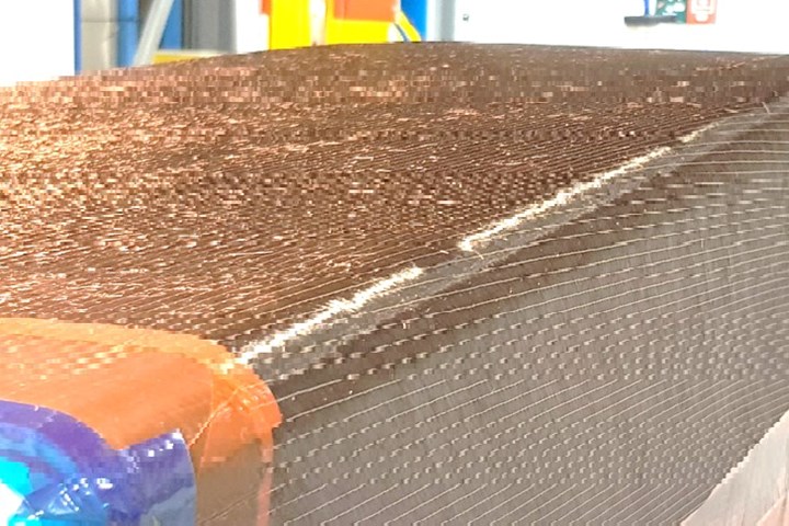
The spar has variable thickness and two angle changes, or “kinks,” over its length. Typically, such a dimensionally complex structure would require cutting and darting of the NCF to avoid wrinkling and the performance knockdowns that would cause. Darting poses challenges of its own, so GKN opted instead to use a novel shearing technique instead. Shown here is the NCF on the forming tool.
Proof at 5 meters leads to 17 meters
In 2019, GKN entered the middle phase of product development with the fabrication of a 5-meter section of the spar. This effort would integrate GKN’s materials and fabrication strategy and demonstrate to Lunney and his team the viability of a large, uncut/undarted, RTM’d structure.
Lunney says he and his team first commissioned fabrication of two male tools — one for preforming and the other for the molding process. The process development started with NCF cut on an automated cutting table, with plies then kitted and placed by hand at prescribed locations on the forming tool. After each layer of plies was placed, it was heated and pressed to stabilize it on the forming tool.
When all plies and all layers were applied, the tool was closed and heated to crosslink the epoxy powder binder and give the NCF rigidity. The preform was then transferred via crane from the preforming tool to the production tool — simply a shorter version of the full-scale tool GKN ultimately planned to develop. This tool featured integrated thermocouples, plus sensors to measure in-mold pressure, resin arrival and degree of cure to help maximize process control.
“We built a lot of automation into the tool,” Lunney says. “We built a lot of sensors, a lot of relatively expensive technology into the 5-meter spar that allowed us to demonstrate that the process was capable of meeting high rate without having to spend that amount of money on the full-scale spar.”
GKN eventually fabricated eight 5-meter demonstrators to assess the material and process capabilities of the system. Three of the 5-meter spars were cut up for mechanical testing; two others were used for corner bend testing. The company also performed extensive nondestructive testing (NDT). All of the test results, Lunney says, were very promising — including <2% porosity — and showed that the M&P strategy GKN developed could work.
This gave the company the confidence it needed to proceed to the final stage — manufacture of the 17-meter mold and the 17-meter spar. Lunney says the biggest technical hurdles on the project were cleared in building the 5-meter spar, thus the migration to the 17-meter spar seemed more manageable.
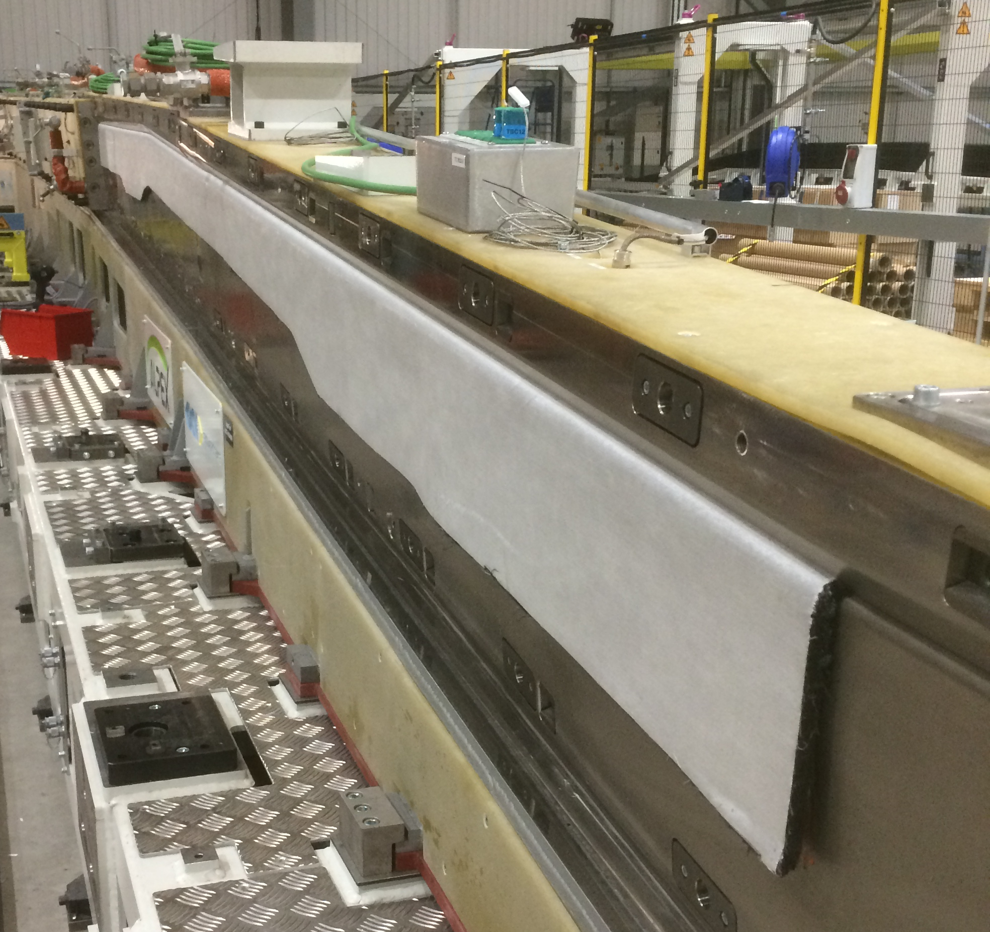
The Alpex production mold is being assembled over the NCF. The NCF preform is partially visible, draped over the side of the tool.
The full-scale forming tool and mold were delivered in mid-2020 and GKN began soon after to manufacture the first full-scale spar. This included automatically cutting plies from rolls of the Teijin NCF and then placing those plies on the forming tool by hand. After the preform was heated and pressurized, it was transferred by a vacuum lifting beam from the preform tool to the production RTM mold.
Possibly the most complex component in the spar’s production is the 17-meter Invar mold, manufactured by Alpex Technologies (Mils, Austria; click here for more from CW on Alpex). Lunney calls it a “jigsaw puzzle of an RTM tool. The middle portion of the tool has to split and actuate so we can remove the spar after molding.”
Other features of the full-scale mold include the same integrated thermocouples and other sensors as used in the 5-meter tool, as well as a fluid heating system with closed loop temperature control.
After it was placed on the production tool, and before resin injection, the preform was trimmed by hand to remove excess material. With the preform in place and trimmed, the mold was closed and sealed and the RTM process was begun with the injection of the Solvay epoxy. The RTM equipment, supplied by Composite Integration (Saltash, U.K.), includes a 200-liter resin delivery system and a pump capable of producing up to 10 bar (145 psi) of pressure.
Before demolding the spar, GKN drilled seven holes directly into the spar through datum holes integrated into the mold itself. These holes, designed to receive fixtures for attaching the spar to the wing box, include five that are 6 millimeters in diameter; the remaining two holes, one each at the root and tip, are 8 millimeters in diameter.
GKN would not reveal total cycle time for the preforming/molding process of the spar, except to say that it’s less than the time required to manufacture the same part via autoclave cure. Ultimately, Lunney says, GKN expects to automate ply placement and drilling to increase manufacturing efficiency and reduce cycle time. “The number of molds we would need to meet rate would be driven by how quickly we can achieve the steps required by the RTM process,” Lunney says. “So it probably would be a multiple of a shift time.” Still, assuming one shipset (two spars) per mold per shift, two shifts per day, five days a week, and GKN is at 44 shipsets a month.
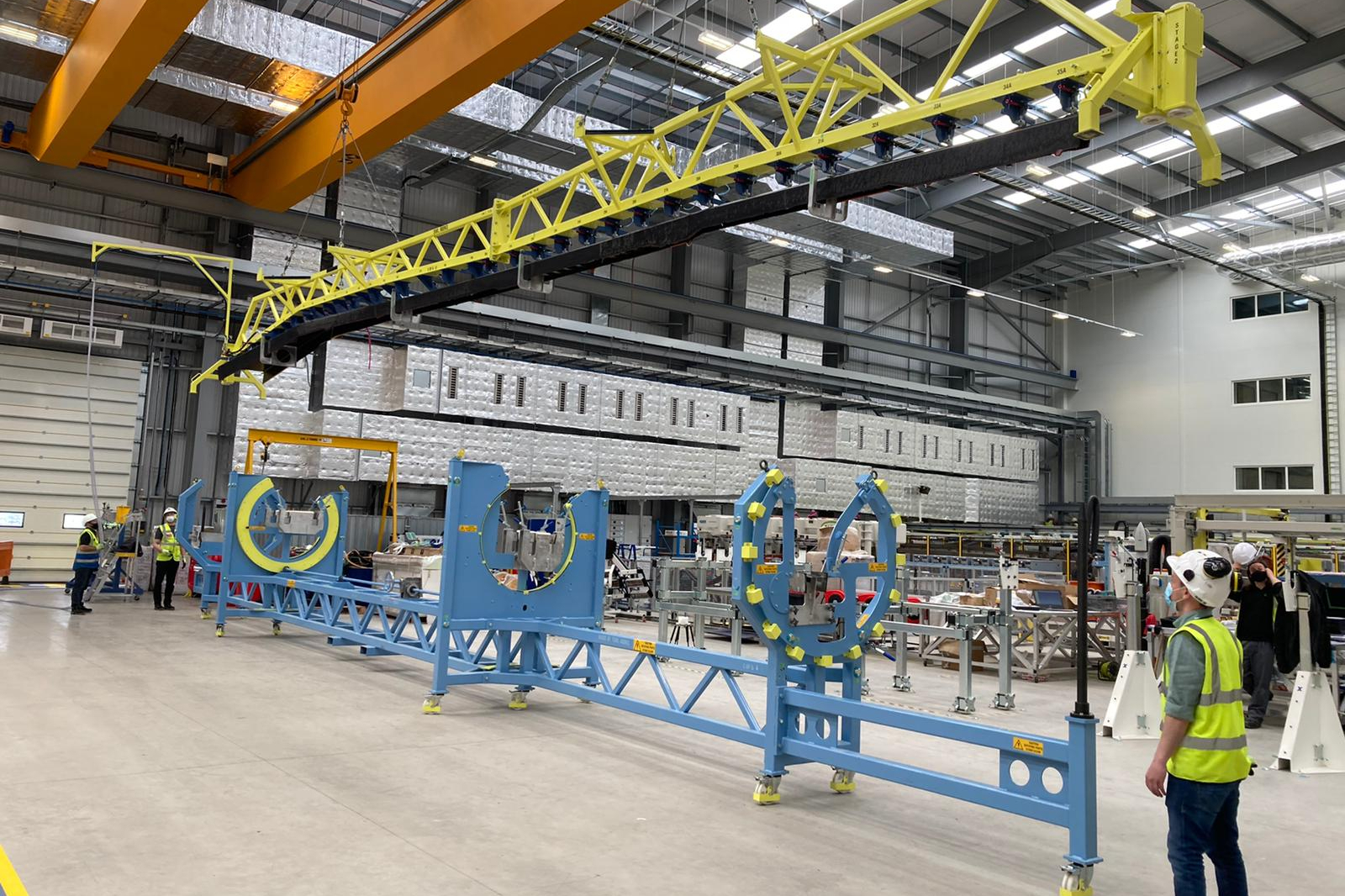
A finished 17-meter spar is lifted from the Alpex production mold and onto an assembly jig. GKN is fabricating four spars as part of the demonstration phase of the Airbus Wing of Tomorrow program.
“Right now, the material is cut on the ply cutter and then manually removed and stored. And then it’s manually positioned on a mobile table and that table is then brought into the cell to position the plies,” Lunney says. “So it is a semi-automated process, whereby we’ve tried to focus on the areas of development that we felt were immature at the beginning of the program, that we need to mature to be able to achieve rate. Obviously, cutting plies and transplanting them onto a table is something that is a relatively high TRL technology that we would automate in the next phases of development. I think the cell that we’ve developed is capable of being fully automated, and we’ve always tried to keep that in mind.”
GKN delivered the first FTE assembly with 17-meter spar to Airbus for the first WOT demonstrator in September 2021. Airbus, for its part, debuted the first WOT demonstrator in July 2022 at the Farnborough International Air Show in Farnborough, U.K. GKN has since delivered a second spar to Airbus, and a third will be delivered soon. A fourth spar, which GKN just completed, will remain with GKN for testing.
Carr says GKN’s ability to develop and deliver the spar so quickly is notable: “I think for the first part to go straight on to a structural test item, and for us to get that right the first time for such a large part for such a large program, has been very significant and very well received by Airbus.”
Looking back and ahead
When asked what was most daunting about development of the WOT spar, Lunney admits it was the decision to forgo cutting and darting of the NCF. “This was a big departure from the norm,” he says. “I was anxious to start, but it got easier as we progressed. Eventually, I was quietly confident we could do it.”
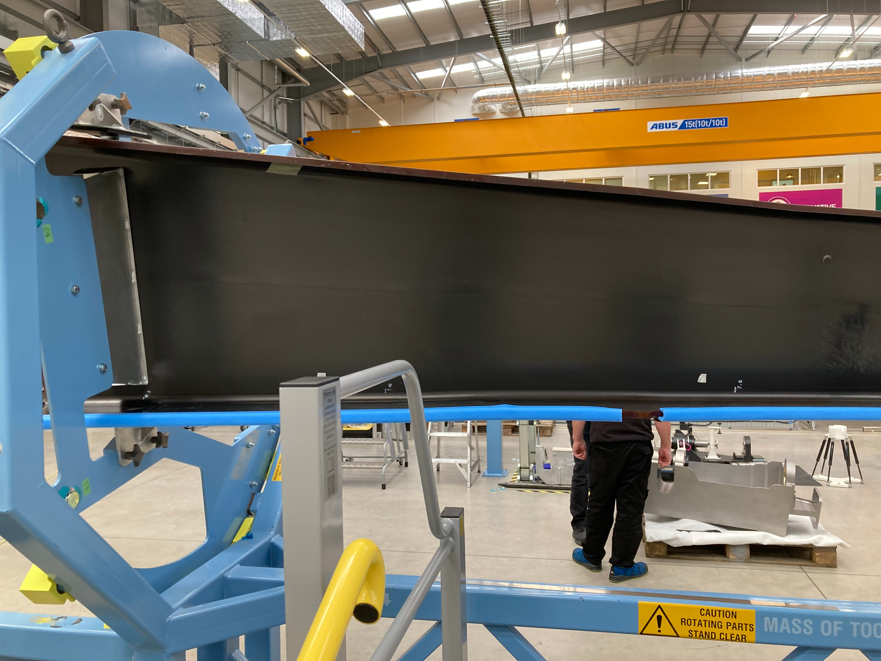
This shows the aft side of a finished spar on an assembly jig at GKN Aerospace. Airbus has already assembled the first WOT demonstrator. It’s possible that some of the M&P from that demonstrator will be applied in the wing structure of a new Airbus aircraft program.
He also says the novelty of the project posed its own challenges: “Forming NCF material was a real challenge. We did not have a process. We couldn’t find anybody else in the world that had a process that would allow us to form that material onto such a complex and challenging geometry in a one-piece ply without any wrinkles, without any darts. I think there was a lot of skepticism at the beginning that we could do this without darting, but we’ve managed to achieve it. I think the second challenge was to take the RTM technology, which is obviously fairly old and mature, and scale it to 17 meters — we had to find suppliers that could help us do it, and then get a tool assembled and functional.”
Of course, Lunney was not alone. He credits his whole team for helping bring the WOT trailing edge spar to fruition. His teammates were: Will Broom, Stephen Williams, Clement Ooi, Phillip Brown, Mark Griffiths, Tim Smith and Tom Bertenshaw. At Farnborough, the entire group was presented GKN’s Chief Executive Award for Technology and Innovation for its development of the spar.
What happens next? The three FTE assemblies delivered from GKN will form part of three wingbox assemblies, one of which will be structurally tested at full scale. GKN is optimistic that its success with the WOT spar positions the company favorably for a possible production contract on a next-gen aircraft program.
In the meantime, GKN is also working closely with several advanced air mobility (AAM) manufacturers that use one-piece wing designs and would benefit significantly from a one-piece composite spar that can be quickly and efficiently manufactured.
“We think it’s the largest one-piece spar in the world,” Lunney says. “We also feel it’s the largest piece of RTM structure in the world, that we are aware of.”
“What we’ve done here is show the quality of the forming process,” Carr says. “We’ve demonstrated the quality of the infusion process. And we have in mind what the right requirements are for a future program.”


Related Content

Combining multifunctional thermoplastic composites, additive manufacturing for next-gen airframe structures
The DOMMINIO project combines AFP with 3D printed gyroid cores, embedded SHM sensors and smart materials for induction-driven disassembly of parts at end of life.
Read More
Otto Aviation launches Phantom 3500 business jet with all-composite airframe from Leonardo
Promising 60% less fuel burn and 90% less emissions using SAF, the super-laminar flow design with windowless fuselage will be built using RTM in Florida facility with certification slated for 2030.
Read More
Reinforcing hollow, 3D printed parts with continuous fiber composites
Spanish startup Reinforce3D’s continuous fiber injection process (CFIP) involves injection of fibers and liquid resin into hollow parts made from any material. Potential applications include sporting goods, aerospace and automotive components, and more.
Read More
Industrializing additive manufacturing in the defense/aerospace sector
GA-ASI demonstrates a path forward for the use of additive technologies for composite tooling, flight-qualified parts.
Read MoreRead Next

From PMCs to sandwich composites: Tracing the path of test method standardization
Over the decades, progression of PMC and sandwich composite test method development and standardization has been shaped by the requirements of the composites industry.
Read More
Robotic computed laminography brings X-ray CT resolution to large composite structures
Omni NDE collaborative robots, X-ray end effectors and Voxray’s reconstruction approach enables 5-micron inspection of aerospace parts without size constraints.
Read More
Composite trends gaining industrial traction for 2026
Startups & Investors topics over the last year show the industry is rapidly gaining maturity while benefiting from macro-trends in circularity, AI and TPC and high-rate manufacturing, all potential gains for investors.
Read More