


Photo Credit: DLR
This blog is a follow-up to a presentation given by the German Aerospace Center (DLR, Stuttgart and Augsburg) at the TU Munich symposium last fall and CW’s summary published during the same time period, “Moving forward on the Multifunctional Fuselage Demonstrator (MFFD)”. The project was also described in a presentation given by Lars Larsen at 9:35 on Day 3 of ITHEC 2020: “Process data-driven advancement of robot-based, continuous ultrasonic welding for the Dust-free Assembly of Future Fuselage Structures”.
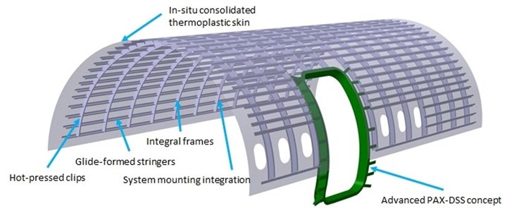
As explained by Larsen, “The major challenge is to show that production costs can be significantly reduced by using automation.” For the MFFD upper half, this includes in-situ consolidation via automated tape laying/fiber placement (ATL/AFP) to avoid the autoclave and dustless/dust-free welding for assembly. “This should make it possible to change the sequence of component and final assembly lines in the future,” says Larsen, “allowing systems to be integrated before assembly.” This is because unlike machining for fastener holes, welding produces no chips or debris that could damage pre-installed systems such as distributed electrical power, interior fittings, etc.


This blog is based on my interview with Sebastian Nowotny, head of component design and manufacturing technologies at the DLR Institute of Structures and Design (BT, Stuttgart) and Frederic Fischer, technical lead for thermoplastic composite production at the DLR Center for Lightweight Production Technology (ZLP, Augsburg). Fischer is also the project manager for the MFFD upper half at DLR.
NOTE: In the image above, glide-formed stringers refers to a process developed within Clean Sky 2 by Applus+ Labaoratories (Barcelona, Spain), see my 2017 blog on glide-forming, and hot-pressed clips refers to stamping, see:
- Accelerating thermoplastic composites in aerospace
- Thermoplastic composites “clip” time, labor on small but crucial parts
- Inside a thermoplastic composites hotbed
Combining structure, cabin and systems
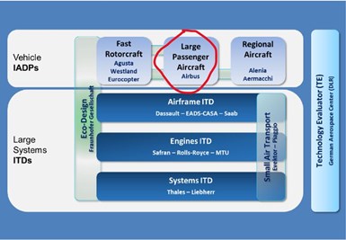
Structure of the Clean Sky 2 Joint Technical Program. Photo Credit: https://www.cleansky.eu/large-passenger-aircraft
I asked Nowotny about the history of the MFFD upper half. “When Clean Sky 2 started, the first call for proposals was issued,” he replies. “I think we started in 2015, and we won the bid for the project called ICASUS, which was a co-partner project for the large passenger aircraft (LPA) program. The main focus was on the design of a multifunctional fuselage. At that time, it wasn't thermoplastic composite. The main goal was to combine the fuselage the cabin, systems and structure into one design process. So basically, the work that was done there is what has now become the multifunctional fuselage demonstrator (MFFD) and is the technology support for our work in the upper shell project.”
How do you combine the fuselage cabin, systems and structure into one? “You would still have those disciplines with their respective requirements, but I think the main goal is the approach to collaborate already in an early stage,” explains Nowotny. “There have been strict rules for the aircraft fuselage design process that have created restrictions and prevented a fully optimized aircraft design. The initial idea to combine structure, cabin and systems was to have a design process that brings these three aspects together and then tries to find the global optimum, not just one first for the cabin and then one for the structure and then one for the systems. But, of course, there are a lot of rules and this is not an easy process because it also involves certification.”
“It’s an ongoing process, in the sense that a digital platform has been established and all European partners provide input into that single digital design,” says Fischer. “Advancing this integrated design for the MFFD is what has been going on for the last couple of years. Our team will deliver the upper half with provisions for cabin and system attachment. The vision is to revolutionize final assembly by delivering fully-equipped major components.”
Although DLR was already part of the design project for MFFD, it did not receive the final go-ahead for the manufacturing project until 2019. The consortium to build the upper half comprises Airbus as the overall MFFD project lead, Premium Aerotec (Augsburg, Germany) as the industrial and structural design lead and supplier of the frames, Aernnova (Vitoria-Gasteiz, Spain) to produce the stringers and DLR as lead for the skin layup and welding technology development. For the past year, says Fischer, “we have refined the upper half design to assure that it can be manufactured with the technologies selected.”
In-situ consolidation
While the lower half of the MFFD is being produced using ATL and AFP followed by autoclave consolidation, the upper half will use in-situ consolidation during ATL/AFP. Why? “To have maximum output from the research project, we chose to challenge the baseline,” says Fischer, “and take advantage of the opportunity to use a technology in complement to the lower half.” Nowotny adds: “We showed that it's a very promising manufacturing method that focuses on lean production reducing manufacturing steps. But I think it's clear there is no one single manufacturing method that serves all purposes. You still have to decide, on a case-by-case basis, what is the optimum manufacturing process for each part.”
Two types of welding
Another choice made for the upper half was the use of two different welding technologies. “We use robot-based continuous ultrasonic welding for the stringers, because, in our opinion, that's the best-suited technology for really long joints, and especially for the stringer configuration,” Fischer explains. Resistance welding was chosen for integrating the fuselage frames. “These choices are the result of intensive analyses that we had in the beginning of the project, together with Premium Aerotec. We looked at the different welding scenarios, what needed to be joined and where.”
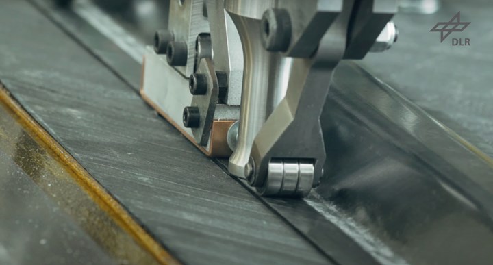
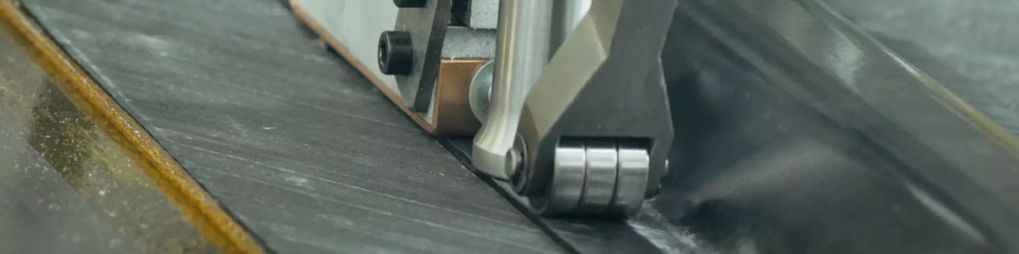
Continuous ultrasonic welding of thermoplastic composite omega stringer to skin. Photo Credit: DLR.
The continuous ultrasonic welding developed by DLR uses a standard industrial robot. The welding end effector comprises a pre-running roller, a 25-millimeter-diameter sonotrode and a following compaction unit. The end effector is equipped with multiple sensors, which enables inline process monitoring. By using the robot as a manipulator, as shown in the video below, a variety of geometries can be welded, such as a curved rear pressure bulkhead or omega stringers onto a skin.
“So, we have two processes with one big distinction,” notes Fischer. “One is a continuous process and the other is a discontinuous process. For the 8-meter-long joints of the Z-stringers, we chose continuous ultrasonic welding. And for the highly complex use-case — in terms of accessibility and tolerance management — to weld the attached flanges of the frames to the skin, we chose resistance welding. We will fit and pre-equip the resistance welding element to the frame geometry and have a clamp-like welding tool that pneumatically closes, contacts the welding elements and then triggers the welding process.”
Nowotny notes that resistance welding has the highest maturity and higher strength, which matches well the higher load seen in the joints between the frames and cleats. He points out that this process is welding the frame to the skin and welding the cleat both to the frame and to the stringer.
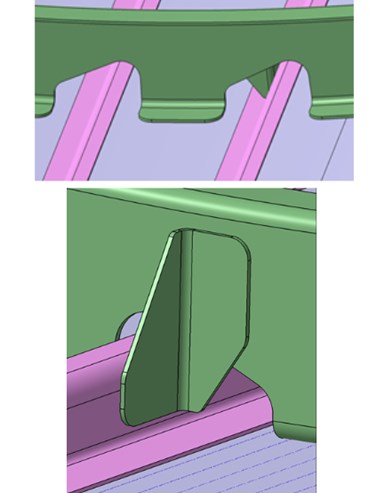
Schematic representation of the cleats that are joined to the Z-stringer and C-frames by resistance welding. Photo Credit: DLR.
“We showed the clip integration on generic parts at JEC 2017,” says Fischer. Nowotny adds, “And we actually had the project HISYS with Airbus Bremen’s high lift department in 2005-2008 for resistance welding with PEEK (polyetheretherketone) thermoplastic. We brought the whole process for welding the ribs into the skin up to TRL 5. So, the basics of the process are quite well understood, and we can now focus mostly on the adaptation, automation and robustness of the process.”
“One of the key enablers for different welding technologies — even though they've been around for a long time — is to show that they are ready for commercial application in industry,” Fischer points out, “including the necessary automation, programming and quality assurance. One of the key issues that we're looking at is how to know that the weld is good. We want to make sure we have the process data to show that we know the weld will perform long-term and that we are not asking for a subsequent NDT check with ultrasonics, or another overall inspection in the completed assembly. So, one of our main goals in this project is developing industrial quality assurance.”

Principle of weld strength prediction. 1. Recording of sensor data during welding process with 1 kHz sample rate. 2. Filtering of process data. 3. Feeding of the welding data into the pre-trained neural network. 4. Prediction of welding strength. Photo Credit: Slide 7, “Process data-driven advancement of robot-based continuous ultrasonic welding for the dust-free assembly of future fuselage structures” by Lars Larsen, ITHEC 2020.
Pivoting to LMPAEK
As explained in my blog, “Proving out LMPAEK welding for Multifunctional Fuselage Demonstrator,” although the MFFD started out with carbon fiber/PEKK (polyetherketoneketone), by the 10th call for proposals (CFP10) in March 2019, the baseline material had been switched to carbon fiber-reinforced LMPAEK (low-melt polyaryletherketone) polymer by Victrex (Clevelys, U.K.). PAEK is the overall family of polymers within which PEEK, PEKK and LMPAEK reside. How much experience does the upper half team have with LMPAEK? “We've used it for a number of manufacturing trials already,” says Fischer. “The material performance is quite promising for both ultrasonic and resistance welding. Still, the material is under development and a process of common exchange in terms of lessons learned and development of processing guidelines has been setup between all European partners and the material supplier.”
“However,” adds Nowotny, “I think it's a good thing that we have these material choices now, because many years ago, there was only Cytec APC-2, and nothing else. Especially in Europe, sometimes you could get the material and sometimes you would get, ‘no, sorry’. Now, we have several material suppliers that actively work on the materials, and also for the different processes. For example, Victrex, as we've seen presented in the 2020 TU Munich symposium, is now looking at optimization for additive manufacturing. There is also some work going on with optimization for AFP in-situ consolidation, and some for secondary consolidation using an autoclave as well as various out of autoclave (OOA) manufacturing processes. So, there's a lot more going on now, and this increases the chances of getting a good material for each process.”
Timeline and next steps
“We've basically finished the design manufacturing process for an intermediate demonstrator — A320 diameter with two frame bays and 950-millimeter-width — and we will build that smaller half-shell at the beginning of next year (2021),” says Fischer. “Apart from that, we have started procurement of the tooling for the full-scale upper half shell, and we are ramping up our technologies to make sure that we'll be able to produce the full-size upper half on-time in 2022.”
What does this entail? One issue is assembly tolerances. “The longitudinal joints along the left- and right-hand sides of both the upper and lower fuselage halves have been designed for some time,” Fischer explains. “From these we have certain requirements, and we need to assure that our production tolerances meet those requirements.”
“The basic story of what we're trying to do with the upper shell is to demonstrate the most efficient routes for production of thermoplastic composites and to pave a way that can compete against aluminum for future aircraft,” says Fischer. He notes that DLR has already shown this in its work with Premium Aerotec to develop a welded thermoplastic rear pressure bulkhead, shown in 2018 and 2019 (see also “New horizons in welding thermoplastic composites”). Welding and lean production are key enablers for thermoplastics. And now we must get these technologies out of the lab and into industry. And for industries to believe that they can really use these welding technologies, we must show that they can be automated, predictable and controlled for reliability in real production tasks. And that's what we are doing.”


Related Content

Plant tour: Sekisui Aerospace, Orange City, Iowa, Renton and Sumner, Wash., U.S.
Veteran composites sites use kaizen and innovation culture to expand thermoplastic serial production, 4.0 digitization and new technology for diversified new markets.
Read More
Composites end markets: Sports and recreation (2025)
The use of composite materials in high-performance sporting goods continues to grow, with new advancements including thermoplastic and sustainability-focused materials and automated processes.
Read More
Combining multifunctional thermoplastic composites, additive manufacturing for next-gen airframe structures
The DOMMINIO project combines AFP with 3D printed gyroid cores, embedded SHM sensors and smart materials for induction-driven disassembly of parts at end of life.
Read More
Assembling the Multifunctional Fuselage Demonstrator: The final welds
Building the all-thermoplastic composite fuselage demonstrator comes to an end with continuous ultrasonic welding of the RH longitudinal fuselage joint and resistance welding for coupling of the fuselage frames across the upper and lower halves.
Read MoreRead Next

Next-gen fan blades: Hybrid twin RTM, printed sensors, laser shock disassembly
MORPHO project demonstrates blade with 20% faster RTM cure cycle, uses AI-based monitoring for improved maintenance/life cycle management and proves laser shock disassembly for recycling.
Read More
Ultrasonic welding for in-space manufacturing of CFRTP
Agile Ultrasonics and NASA trial robotic-compatible carbon fiber-reinforced thermoplastic ultrasonic welding technology for space structures.
Read More
Cutting 100 pounds, certification time for the X-59 nose cone
Swift Engineering used HyperX software to remove 100 pounds from 38-foot graphite/epoxy cored nose cone for X-59 supersonic aircraft.
Read More