
Liquid Composite Molding Achieves Aerospace Quality
Improvements in materials, tooling and process control bring RTM and VARTM into the realm of aerospace components.


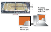
Source: Army Research LaboratoryThe SMARTweave embedded sensor grid enables a real-time display of the resin flow front in RTM and VARTM systems.
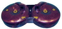
Source: V System CompositesManifold lids for the Comanche helicopter, built using RTM.
Autoclave curing has long been the "gold standard" for aerospace composite parts. Very few processes can match the consistent part quality and high fiber volume of prepreg laminates cured in an autoclave. Although hand layup dominates autoclave processes, automated cutting tools and laser placement systems driven by computer-aided design (CAD) programs minimize part-to-part variations and reduce labor costs. Fiber placement brings the autoclave process even closer to complete automation.
Still, autoclave processing remains expensive, especially for medium- to large-size production runs. The capital cost for the autoclave is high, and fiber placement equipment is usually even more expensive. Maintenance and operating expenses tend to be higher than for ovens, presses and similar equipment. Finally, with cycle times measured in hours, larger production rates require multiple autoclaves or larger interior volumes.


With military budgets under increasing pressure, engineers must look for alternative processing methods that can reduce costs while maintaining the high performance of autoclave-cured components. Within the last few years, liquid composite molding (LCM) technologies have advanced to the point where they can provide that alternative. LCM processes are characterized by the injection of a liquid resin into a dry fiber preform, and include resin transfer molding (RTM) and vacuum-assisted RTM (VARTM).
In conventional RTM, the preform is placed into a closed, matched tool and resin is injected under pressure on the order of 0.69 to 1.38 MPa (100 to 200 psi). Early RTM processes, however, lacked the consistency needed for aerospace components, in both dimensional tolerances and mechanical properties. Fiber volume fractions were significantly lower than the 60 to 65 percent typical of prepregs. Problems with predicting flow fronts as well as flaws that were introduced into the preform when closing the matched metal molds often led to high void contents and dry spots.
Improvements in both materials and processes, though, have recently made RTM a viable option for aerospace manufacturing. Paul Oppenheim, vice president of programs and business development at V System Composites (VSC, Anaheim, Calif., U.S.A.), explains that it normally takes 10 to 15 years for a new technology to become accepted in the aerospace industry. With RTM, the breakthrough began about five years ago, when Lockheed Martin (Fort Worth, Texas, U.S.A.) selected RTM for many of the F/A-22 Raptor's structural components. Composites comprise approximately 27 percent of the F/A-22's structural weight (24 percent thermoset and 3 percent thermoplastic). RTM accounts for more than 400 parts, made with both BMI and epoxy resins. The wing's sine-wave spars were probably the first structural application of RTM composites in an aircraft. For a vertical tail on another Lockheed Martin aircraft, the RTM process reduced the part count from 13 to one, eliminated almost 1,000 fasteners, and reduced manufacturing costs by more than 60 percent.
Developing material properties databases
A general lack of material properties databases has slowed the adoption of RTM in the aerospace industry. Most large companies spend several years and tens or even hundreds of thousands of dollars qualifying composites for structural applications. Using prequalified materials produces a significant savings in development cost and time. Composite manufacturers like VSC, though, are seeing a willingness to develop databases for RTM materials.
Since the RTM process is more complex than autoclave curing, it is more difficult to develop a general qualification methodology. With prepregs, the material manufacturer mixes the resin and impregnates the tape or fabric under highly controlled conditions. Once a material is qualified under the AGATE methodology (see HPC May 2003, p. 38), for example, an end user just has to demonstrate site equivalency of its manufacturing process. With RTM, however, both the resin mix and the resin content are more variable. In particular, the final resin content depends on maintaining a good flow front. Still, it is possible to develop general allowables for RTM systems. An October 2001 AGATE report outlines a general method for qualifying braided RTM systems. The methodology has been used to qualify RTM parts made with a PR250 resin (Cytec Engineered Materials Inc., Tempe, Ariz., U.S.A.) and an AS4 carbon fiber (Hexcel Corp., Dublin, Calif., U.S.A.) braid produced by A&P Technology Inc. (Cincinnati, Ohio, U.S.A.). Unlike other AGATE materials, though, the allowables are specific to the part manufacturer, Raytheon Aircraft Co. (Wichita, Kan., U.S.A.).
Virtual molding
The high cost of tooling also limits the adoption of RTM. A set of production tools can cost on the order of $500,000 (USD), according to Oppenheim. Although the price is competitive with autoclave tools, autoclave programs can usually get by with a single set of tooling for both development and production. With RTM the resin flow front (and hence the part quality) is highly dependent on the tooling geometry. Often it is necessary to build one or more sets of prototype tools, to develop and test the process, before the production tooling can be built. Although prototype tooling is less expensive than production tooling, it is not so inexpensive that it can be considered expendable.
Simulation of the molding process can predict flow fronts, allowing engineers to virtually test different mold designs without building expensive hardware. Lockheed Martin, in the development of the vertical tail described above, worked with the Air Force Research Laboratory (AFRL, Wright-Patterson AFB, Ohio, U.S.A.) and the University of Dayton Research Institute (Dayton, Ohio, U.S.A.) to model the resin flow. They were able to identify preferred injection sites and sequences to achieve complete mold filling with no dry spots.
Modeling of the flow front depends on a large number of variables, including preform geometry and permeability; resin temperature, viscosity, pressure, and cure state (all of which vary with both time and position); mold geometry; heating elements; and the location of injection ports and vents. The complex physics of the process means that finite element programs are generally used for the simulation. Research groups like AFRL and the University of Delaware's Center for Composite Materials (CCM, Newark, Del., U.S.A.) continue to develop such programs and improve their accuracy. A few commercial programs also are available.
The PAM-RTM program from ESI Group (Paris, France) simulates the entire molding process before the tool is made. Part geometry is defined within the PAM-RTM program and converted into a finite element mesh. PAM-RTM can import fiber orientations predicted by the draping module of VISTAGY's (Waltham, Mass., U.S.A.) FiberSIM program, improving the preform model and providing a more accurate simulation of resin flow. The user places injection and venting ports, defines resin viscosity profiles and sets heat sources. PAM-RTM then calculates the resin flow front, pressure and temperature distribution, and cure profile. Animated plots of the flow front make it easy to identify problem areas, such as dry spots. Adjusting the processing parameters within the simulation allows the user to find optimum configurations that minimize molding time, resin waste and other costs.
A similar program, RTM-Worx from Polyworx (Bergambacht, The Netherlands), provides simulation of both RTM and vacuum infusion processes. Geometry can be constructed either with the built-in modeler or imported from a DXF, STL or finite element mesh file. The program can also import draping analyses from MSC.Patran Laminate Modeler (MSC.Software, Santa Ana, Calif., U.S.A.). The built-in mesher allows for either automatic, graded meshing or explicit user control over element size. Users place injection and venting ports, and specify input properties, such as resin viscosity at the injection temperature, fiber volume fraction and permeability.
RTM-Worx calculates the resin flow front and cure profile at several time steps, resulting in an animation of the entire filling process. A control volume method is used, which solves early steps more quickly because only the active elements (those partially or entirely filled with resin) are modeled for each successive step. To save additional time, users typically start with coarse meshes to get quick results and identify potential problem areas, then proceed to a fine but slower mesh for more accurate results.
Flexible resin injection systems
Despite the promise of process modeling, smaller RTM manufacturers seem reluctant to rely entirely on simulation. John Plessinger, president of John Plessinger Consulting (Miamisburg, Ohio, U.S.A.) sometimes worked with universities to model RTM processes at his former company, Design Evolution 4 Inc. (de4, Lebanon, Ohio, U.S.A.). However, as the part geometry became more complex, and the number of fabrics in a single preform increased, the simulations became less reliable. As a result, he found it more effective to simply build tools with extra injection ports and vents, then try different combinations in the prototype phase.
To speed the development process, Plessinger developed the Automatic RTM Injection System, or ARTMIS. Each injection port is pneumatically operated, and can be opened and closed at any time during the injection process. Each port also has its own pneumatic flush valve, which flushes the entire line (injection gun, static mixers, manifold and port) automatically, so there is no concern about port clogging. During the development phase, flow sensors track the movement of the flow front. By observing the front on a light board, the operator can turn ports off and on as needed to avoid dry spots. The sequence and timing of the injection process is documented, allowing the ports to be computer controlled during production. Even without the automation, Plessinger found ARTMIS saved time in production. To prevent clogging, lines must be alternately flushed with solvent and air a number of times. ARTMIS eliminates the possibility of running too few flush cycles, and allows the operator to begin work on the next part while the lines flush. ARTMIS systems have been used on a number of projects, including a multiport system for a 4.3m/14 ft missile body prototype, ion implantation radiation doors used in the semiconductor industry, and an 11-port system used in the development of a one-piece, prototype electric vehicle chassis.
Hybrid processes
"Ask 100 people to define RTM, and you will get 100 different answers," says Michael Louderback, president and general manager of VSC. Each manufacturer has its own version of RTM, and in many cases the differences are great enough to consider the process unique. The variations are even greater for VARTM, which can include a boat hull manufacturer using SCRIMP and an aerospace manufacturer using all-steel molds with vacuum only. VSC has three versions — classical RTM, HyPerVARTM and HyPerRTM — each tailored to a different need.
Louderback credits much of his company's success with RTM on the experience of his engineers and technicians, and their understanding of the process. But success is also due to the specific features built into the process. Tool design is critical. Engineers must pay close attention to how the injection ports are gated, how the resin moves through the tool and the ability of the tool to hold hard vacuum or high pressure. VSC works closely with tooling vendors such as North Coast Tool & Mold Corp. (Cleveland, Ohio, U.S.A.) to ensure that molds are designed for production-worthiness, meaning even the heaviest molds must go together quickly, come apart quickly and, in general, be easy to handle. VSC's tool designs also incorporate several different high-thermal-expansion materials in order to drive the preforms to net thickness and optimal fiber volume.
Although VSC relies on experience for good tool design, Louderback sees a place for flow simulation, especially for more complex tools. "A good model can minimize prototyping," he explains, "but it is important to combine practical lessons learned with the analysis." Many times, the person running the code is not familiar enough with the RTM process to spot potential problems. For example, the infusion analysis assumes the resin will remain contained within the preform. In practice, though, the resin will find alternate paths that the model doesn't predict. "The model can help confirm a tooling design, but it isn't a substitute for good engineering," says Louderback.
Understanding the materials, and especially the resin, also is important to achieving high quality in a part. Resin viscosity and cure profiles must be quantified and documented. These properties are used in the prototyping phase to develop a process specification for each part. During production, the spec must be followed and run in the same way every time. To ensure uniformity, VSC controls its process with the Sentinel system from CompuDAS (Shelton, Wash., U.S.A.), a general-purpose industrial controller commonly used in the composites industry to control autoclaves (see HPC March 2003, p. 27). In fact, the same hardware can control any thermal system, including autoclave, RTM, VARTM and other industrial processes. The difference lies in the software user interface. For VSC's RTM system, CompuDAS designed an interface that enables the operator to control processing variables, such as vacuum, pressure and temperature. Although the system has the capability to turn injection ports on and off, and thus fully automate the process, the system is designed to pause the process at key operator decision points, such as for leak checks and resin temperature verification.
In addition to classical RTM, VSC also has developed the HyPerVARTM process (pat. pend.) — a resin infusion system targeted to the aerospace industry. Most VARTM systems use a flow medium to get good resin coverage. This works well for relatively simple structures like boat hulls, but cannot handle the features and complexities common in aerospace components, such as multiple buildups and ply drop-offs. HyPerVARTM is a single-point-of-injection system. Resin delivery is designed into the tool, eliminating the infusion medium and significantly reducing other consumables and touch labor, which translates into much lower costs. Selective control of permeabilities throughout the part provides excellent control over fiber volume fractions. The process is ready for production, and has been proven on the CH-47 helicopter's forward pylon deck, built for Boeing Rotorcraft (Philadelphia, Pa., U.S.A.), and on a Ka band deep space reflector built for NASA's Jet Propulsion Laboratory (JPL, Pasadena, Calif., U.S.A.). Airbus is currently evaluating HyPerVARTM for production use, as well.
The next phase in VSC's process development is the HyPerRTM process, which the company says combines the best of HyPerVARTM with classical RTM. HyPerRTM molds are built using the HyPerVARTM process, and can incorporate some metallic details where necessary. Resin distribution details also are built into the HyPerRTM mold. HyPerRTM enables VSC to produce parts with the high quality of classical RTM but at the price of HyPerVARTM.
Closing the loop
The Sentinel system has the capability to take input from temperature, pressure, cure and flow-front sensors and use that data to control the entire RTM process. Such closed-loop control systems are finding use in autoclave systems, but they have yet to be embraced by RTM manufacturers. "We don't really have a need for feedback control in RTM," says Louderback. "Once we have developed the process and cure specs, we just run the process the same way every time."
Still, as technology continues to improve, feedback control systems may find their place in RTM processing. The University of Delaware CCM is investigating active control in a number of ongoing research projects. Most center on Netzsch Instrument's (Burlington, Mass., U.S.A.) SMARTweave system. A SMARTweave array is made by aligning conductive fibers in a two-dimensional grid pattern. Small gaps where the fibers cross act as sensors. The grid can be embedded into the laminate without affecting material properties. One lead wire is required for each fiber. This makes the system very efficient: a 10 by 10 array, for example, requires 20 wires but provides 100 sensor points. Each sensor point can detect the resin flow front. A single array provides a two-dimensional, real-time picture of the flow front. Embedding multiple arrays at various locations through the thickness of the laminate can provide a three-dimensional model of the front.
Shawn Walsh, inventor of the SMARTweave system and team leader of the Intelligent Materials and Processing Group at the Weapons and Materials Research Directorate of the U.S. Army Research Laboratory (ARL, Aberdeen Proving Ground, Md., U.S.A.), is using SMARTweave in the development of the Composite Armored Vehicle (CAV). The CAV will demonstrate the use of lightweight composite armor on a C-130 air-deployable, 22-ton vehicle. The vehicle structure and armor will weigh at least 33 percent less than comparable steel or aluminum. SMARTweave is used both to verify flow models and to control part quality. Real-time sensor information is fed into a finite element model of the flow front. The model predicts where the flow front will be in the future. If a problem is anticipated, such as a weld line or dry spot, then it can be corrected by adjusting the injection pressure or flow rate. CAV armor consists of thick ceramic pieces sandwiched between several layers of glass fabric. The resin must flow through tight gaps between the ceramic pieces, making flow prediction and process development very difficult. The ceramic is enormously expensive, so catching mistakes before they happen is crucial to keeping costs down.
As aerospace RTM components move into higher production rates, however, SMARTweave might become more cost-effective. "A high-volume application would allow manufacturers to develop a standard grid for their product," explains Walsh. "The sensor leads then could be connected into a single-harness cable, eliminating the need for time-consuming wiring on the shop floor." Such an improvement might entice manufacturers to incorporate SMARTweave into their RTM and VARTM systems. Although it is unlikely to be used in a closed-loop control system, the data gathered during infusion might eliminate the need for post-cure nondestructive evaluation.


Related Content

Composite resins price change report
CW’s running summary of resin price change announcements from major material suppliers that serve the composites manufacturing industry.
Read More
Prepreg compression molding supports higher-rate propeller manufacturing
To meet increasing UAV market demands, Mejzlik Propellers has added a higher-rate compression molding line to its custom CFRP propeller capabilities.
Read More
Induction heating system enables OOA composites processing
JEC World 2025: Roctool focuses attendees’ attention on the light induction tooling (LIT) system targeting efficiency, sustainability and performance.
Read More
Composite Integration presents webinar on liquid resin infusion
On July 30, 2025, company experts will discuss the role of LRI in delivering scalable, OOA composite production for the aerospace sector.
Read MoreRead Next

Scaling up, optimizing the flax fiber composite camper
Greenlander’s Sherpa RV cab, which is largely constructed from flax fiber/bio-epoxy sandwich panels, nears commercial production readiness and next-generation scale-up.
Read More
Ceramic matrix composites: Faster, cheaper, higher temperature
New players proliferate, increasing CMC materials and manufacturing capacity, novel processes and automation to meet demand for higher part volumes and performance.
Read More
Ultrasonic welding for in-space manufacturing of CFRTP
Agile Ultrasonics and NASA trial robotic-compatible carbon fiber-reinforced thermoplastic ultrasonic welding technology for space structures.
Read More