
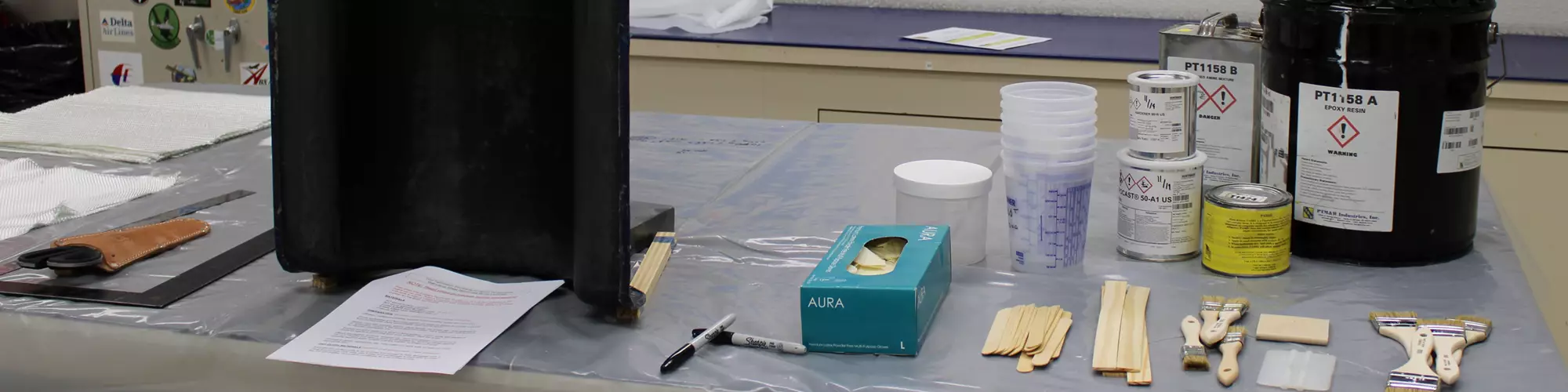


Fig. 1. Plan to have everything that is needed within reach of the operator and support staff. Photo Credit, all images: Abaris Training Resources Inc.
Open mold, wet layup processing of glass and carbon fiber epoxy laminates has come back on my radar in recent months, as clients continue to fabricate composite tools and parts using this methodology with mixed success. This is particularly true when making laminates by hand with dry fabric layers and two-part reactive epoxy resins without the aid of vacuum bag compaction.
Some of the commonly reported problems using this approach include:


- Surface coat resin layer cracking or crazing over time.
- Pitting on the surface of the tool or part after demolding.
- The surface coat looks marbled or discolored in places.
- Laminating resin gels too quickly during layup.
- Blister formations develop at the fine-fabric interface to the surface coat.
- Underlying bulk fabrics slide or sag on vertical surfaces during layup.
- Backside of finished laminate is rough.
How can we solve or mitigate some of these problems? This month, we provide possible solutions, which will also produce better laminates.
Planning/staffing
Planning and timing are everything to a successful wet layup process. The work area should have everything necessary to accomplish the layup within reach of the operators before starting (Fig. 1). All resins should be weighed, covered and on standby to be mixed upon demand. All fabric pieces should be precut and within reach of the operators. The mold or model for the tool should be released and ready to go. Size matters — it is best to have at least two operators for smaller laminates and more personnel as the project size increases. The ideal is one layup operator for every 1.5 square yards (1.25 square meters) of area, and a support staff that is mixing and supplying resins, fabrics and other supplies to the layup operators.
Issues with the surface coat resin
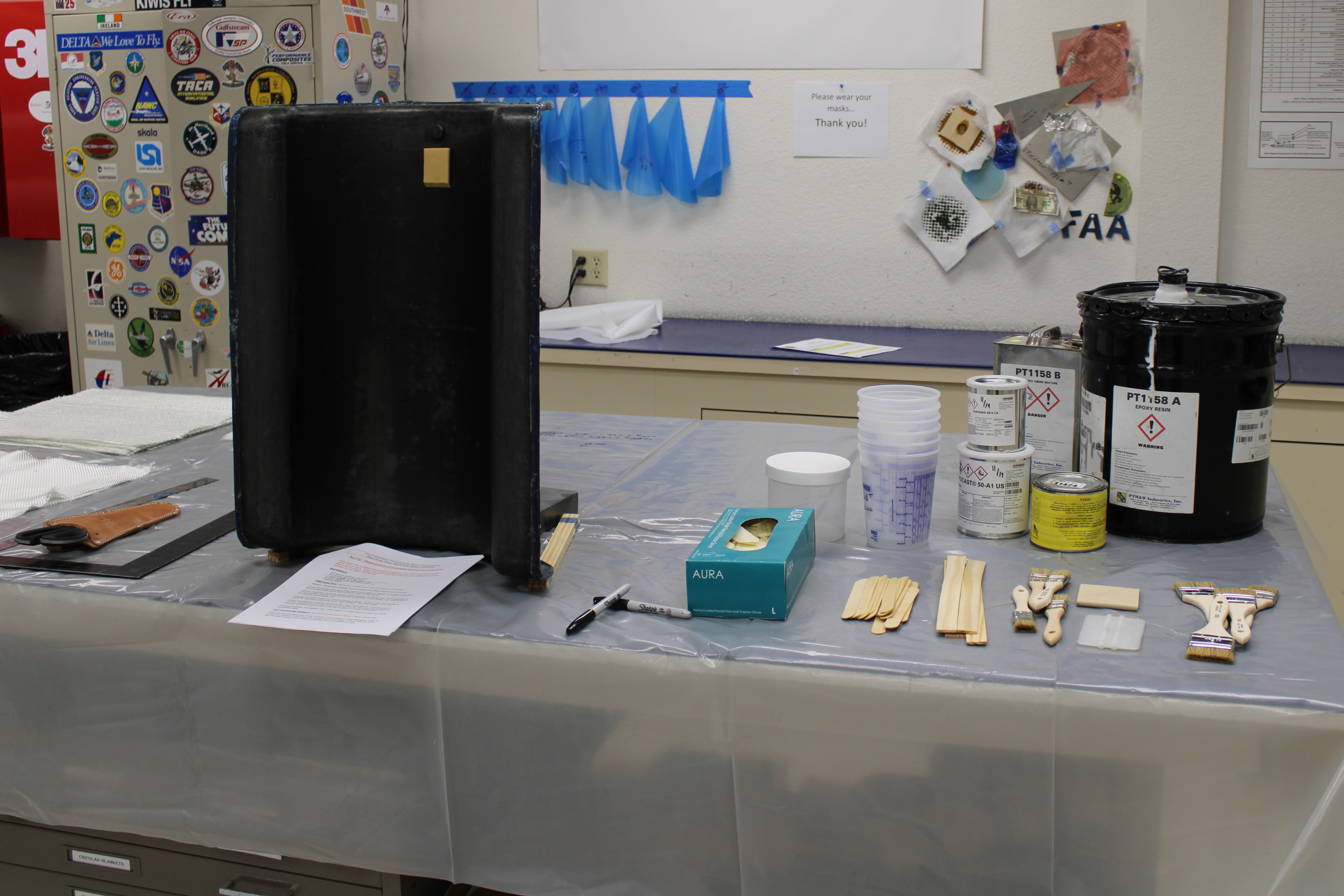
The surface coat (SC) layer is primarily a cosmetic layer; however, certain formulas can provide for extra abrasion resistance. Compared to laminating resins with low-to-medium viscosities, SC resins are mostly filled, thixotropic resins that are designed to resist sagging on vertical surfaces. Epoxy SCs should not be confused with polyester gel coat resins that are sprayed, but are instead applied by hand. First, a squeegee is used to quickly spread the mixed epoxy resin over the surface. The resin is then brushed in two directions with appropriately sized (short bristle) brushes until uniformly distributed and all trapped gas is removed (Fig. 2). Choose an SC resin system that has desired application properties for best results (see resin selection and handling tips paragraph below).
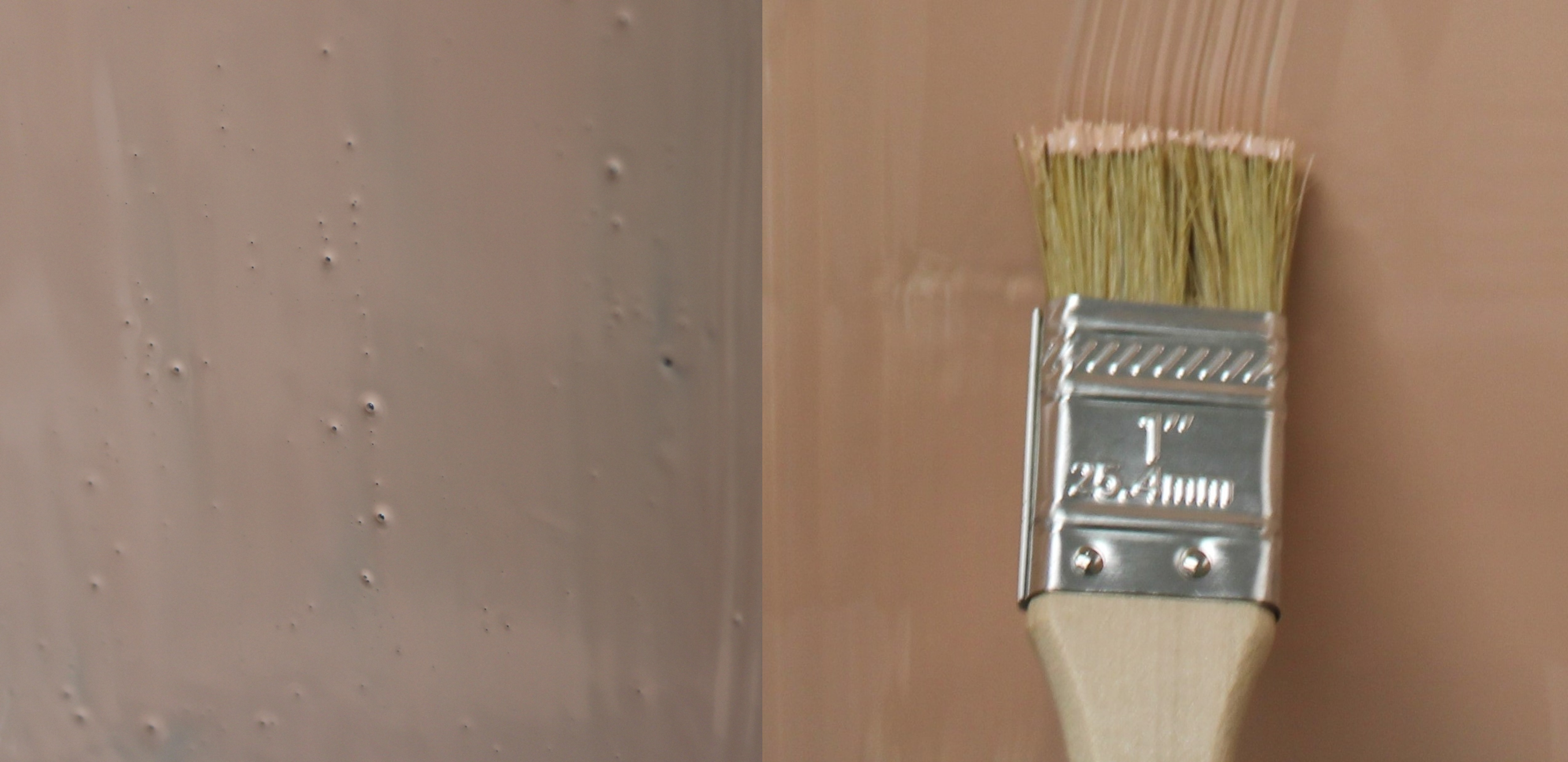
Fig. 2. Brush out gas bubbles (left) in the surface coat layer as they form. After the first pass, it is best to come back a few minutes later and repeat the process until all bubbles are gone and a uniform thickness is achieved (right).
Refer to the material data sheet for the specific gravity of the mixed resin and calculate the weight in grams needed to cover the area to be laminated using the following steps:
- Multiply the specific gravity (grams/cubic centimeter) of mixed SC resin x 16.39 = grams per cubic inch. (For example, 1.25 x 16.39 = 20.49 grams per cubic inch.)
- Divide this value by 100 to get the grams per square inch at 0.01-inch thick. (20.49 ÷ 100 = 0.205 gram per square inch at 0.01-inch thick.)
- Multiply grams per square inch by 144 = grams per square foot at 0.01-inch thick. (0.205 x 144 = 29.5 grams per square foot at 0.01-inch thick.)
Fig. 3. Use a gloved finger in the trim area to test the level of gel in the surface coat layer. It is ready when the fingertip leaves an impression without transferring to the glove.
It is important to weigh, mix and then transfer the mixed SC resin to a second container and mix it again with a clean stir stick. This “double cup” method prevents marbling or discoloration of the SC. The entire mixed batch should be immediately distributed out of the container(s) as described above. This preserves the reaction time of the resin, allowing the operator time to completely brush out emerging gases and achieve a uniform thickness.
To avoid future cracking or crazing, and to minimize the chance of surface pitting, the SC resin thickness must be controlled, usually between 0.01-0.03-inch (0.25-0.75-millimeter) thick. The thicker the SC is applied, the more difficult it is to remove trapped air/gas and the more susceptible it will be to shrinkage, cracking and crazing while in service.
It is typical, but not always required, to allow the SC resin to gel to a “finger tack” before proceeding with an interface coat of resin and first ply layup (Fig. 3). This minimizes the chance of the fabric showing on the surface. However, for laminates subjected to elevated temperature service, it may be desirable to have fiber reinforcement worked into the SC layer (post-interface coat) to ensure against cracking or crazing through thermal cycling.
Resin selection and handling tips
Timing is everything in the wet layup process. Choosing the appropriate hardener(s) for the laminating resin gives the operator some control over the rate of reaction (short, medium or long pot life). Preserve pot life and working time of the resin by weighing the calculated amount for each ply in large-volume containers (not small cups) so that the resin is not concentrated and is less prone to rapid exotherm. The thinner the resin cross-section in the container, the slower the reaction rate. Distribute the mixed resin quickly (with a squeegee) to coat the previous surface, install the ply, work out the trapped air and wrinkles by stippling with cut-bristle brushes or soft rollers.
Low-viscosity resins wet out the fabric well but can also be slippery and enable heavier plies to sag on vertical surfaces (Fig. 4). In most cases, choosing a (calcium carbonate) filled laminating resin can help minimize slipping and keep the resin from running out of the fabric layer(s). One effective method to control sliding or sagging is to stage each layer to a quasi-gel state prior to adding the next layer(s). For example, use a shorter pot life system for the first layer so that it is stable/unlikely to move and then graduate to a longer pot life system for subsequent plies. The idea is to choose a combination of resin properties that will work best for the project and not try to adapt one resin/hardener system for all laminate sizes and configurations. Another idea is to tape or otherwise restrain each fabric ply so that it cannot physically slide down the vertical walls.
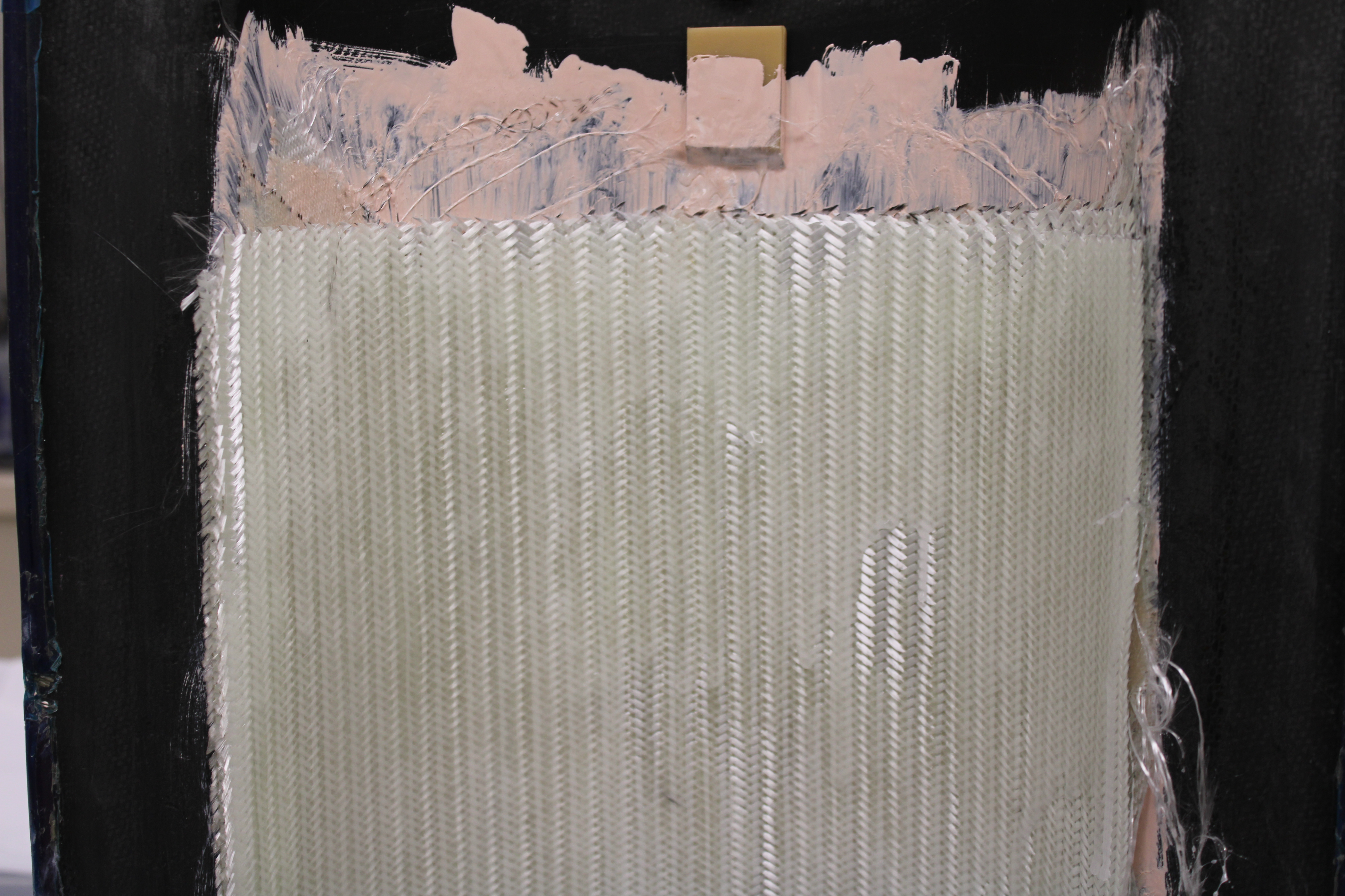
Fig. 4. The weight of a heavy fabric ply causes the underlying plies to slide, taking the surface coat layer with it. This can be mitigated by staging or mechanically restraining each layer to prevent movement.
Choose friendly fabrics
Fine woven fabrics such as style #120 or #1581 glass, or 1K, 5-harness satin carbon fabrics, seem like a good choice for a surface ply (or plies), but these tightly woven fabrics can trap evolving gas or air and “blister” at the SC-ply interface if not worked extensively during layup. A fine yarn plain or twill weave fabric is better at allowing both resin and gas/air to move through each layer without much effort. Choose a medium-weight peel ply fabric to apply to the backside of the layup for a smoother surface. Avoid over-compacting — use a light touch when distributing resin on each ply to minimize porous areas at the void space between yarns in the fabric. This may be counterintuitive to those that work with vacuum-/pressure-compacted prepreg materials where a fine-yarn, tight-weave fabric might work better (reference “Porosity, voids and bridging in prepreg autoclave and vacuum bag-only laminates” for more information on this topic).
Standardize and optimize
It is extremely helpful to create standard procedures for wet layup and to train all operators to follow them without shortcuts. Typically, experienced operators have their own methods and techniques — some good, some not so good. Harvest the good and dump the bad habits, especially those that sacrifice quality in the name of time. Be flexible with revisions that will further optimize the process. The procedure is a “living document” that builds upon lessons learned. Teach everyone best practices and foster success through the learned experience. It will lead to better quality products and a more productive team.


.jpg;maxWidth=300;quality=90;format=webp)


Related Content

Carbon fiber in pressure vessels for hydrogen
The emerging H2 economy drives tank development for aircraft, ships and gas transport.
Read More
One-piece, one-shot, 17-meter wing spar for high-rate aircraft manufacture
GKN Aerospace has spent the last five years developing materials strategies and resin transfer molding (RTM) for an aircraft trailing edge wing spar for the Airbus Wing of Tomorrow program.
Read More
Novel dry tape for liquid molded composites
MTorres seeks to enable next-gen aircraft and open new markets for composites with low-cost, high-permeability tapes and versatile, high-speed production lines.
Read More
Plant tour: Spirit AeroSystems, Belfast, Northern Ireland, U.K.
Purpose-built facility employs resin transfer infusion (RTI) and assembly technology to manufacture today’s composite A220 wings, and prepares for future new programs and production ramp-ups.
Read MoreRead Next

Avoiding the pitfalls of vacuum infusion processing
Understand the fundamentals of vacuum infusion processing (VIP), including pressure, permeability and race tracking, to prevent issues and produce consistent results.
Read More
Troubleshooting thermoforming of thermoplastic composites
Challenges with the thermoforming/stamping process and potential solutions addressing the associated parameters and complex material behaviors.
Read More
Alternate heat sources for hot-bonded composite repairs
Successfully using an alternate heat source for repairing composite structures requires an awareness of thermal dynamics and effective heat transfer management.
Read More