
Industrializing additive manufacturing in the defense/aerospace sector
GA-ASI demonstrates a path forward for the use of additive technologies for tooling, flight-qualified parts.


Over the last 13 years, General Atomics Aeronautical Systems Inc. (GA-ASI) has explored the use of polymer/composite and metal additive manufacturing (AM) as a cost- and time-saving alternative to conventional manufacturing, not only for tooling to produce advanced composite parts, but also for flight-qualified parts themselves via the company’s unmanned aerial systems (UAS). Photo Credit, all images: General Atomics Aeronautical Systems Inc.
When unmanned aircraft systems (UAS) company General Atomics Aeronautical Systems Inc. (GA-ASI, Poway, Calif., U.S.) began experimenting with polymer additive manufacturing (AM) circa 2011, a small team used the technology to rapidly prototype parts that would subsequently be produced in advanced composites. Since it was so much faster to print than hand layup and cure parts, this approach provided a quicker and less costly method to rapidly move through multiple design iterations, focus on the best option, then produce tooling and trial actual molded parts.
Over the next few years as it added more printers — including polymer, and later, metal printers representing multiple additive technologies — GA-ASI envisioned further uses for AM technology and began a program to explore production ramp-up and commercial adoption. By 2018, the first flight-qualified polymer AM part was flying on the company’s UAS and by 2019 its first flight-qualified metal additive part was in use. In 2021, the company opened a 700-square-meter Additive Designs & Manufacturing Center of Excellence in Poway, staffed by a team of 14 AM subject matter experts (SMEs) who focus on AM-related production, new application development and R&D projects. By 2026, that facility is expected to expand to 1,858 square meters with a concurrent increase in staff.


To date, GA-ASI says it has developed more than 350 flight-qualified AM parts and produces more than 7,500 production AM parts annually that have successfully completed over 300,000 hours of cumulative flight. The company forecasts growth rates to rise from 25% to 35% per year. How did GA-ASI move from prototyping to industrial adoption of AM tools and parts in the demanding aerospace/defense sector in roughly a decade?
“First we demonstrated to ourselves, then to our management, and later to key customers, the many, often compounding, benefits that additive technology can bring to programs — not just during the prototyping phase but also as low-rate initial production [LRIP] gets underway,” explains Steve Fournier, GA-ASI senior manager, Additive Designs & Manufacturing Center of Excellence and department. He says it’s vital to differentiate between prototype projects (doing it right once) versus production projects (doing it right 100+ times in a row) and to find the right applications early on to drive establishment of the elements of an AM ecosystem for application families that have a good chance of success. It’s also important to ensure that proper business case assessments are performed before technical development gets underway.
“Another critical aspect is to ensure you’re using the correct material, process and design for each application — and it does take time to develop guidelines to design for additive manufacturing,” Fournier continues. “For GA-ASI, buying printers so we could have a fast learning curve was important to our success and brought benefits at the aircraft level that wouldn’t have been possible if we hadn’t strategically built a centralized, consolidated AM infrastructure near where we build our UAS. However, we didn’t operate in a vacuum when building our expertise. Instead, we worked with other GA divisions, as well as strategic suppliers and customers. That helped us grow in competence without needing large CAPEX investments before we proved out the technology and achieved ROI.”
Early challenges
Moving from prototyping to industrial implementation was neither simple nor straightforward. The team at GA-ASI faced many challenges, including learning to navigate the differences between conventional engineering design and design for AM (DfAM), dealing with the higher cost of AM materials and the time and cost required to qualify them, plus the high, nonrecurring engineering (NRE) costs to develop and qualify new AM applications. It also took time to build adoption confidence within engineering, manufacturing and quality stakeholders, to secure funding to support increased staffing, equipment and R&D allowances, and to recruit and train staff.
“You need a coherent strategy to reduce risk and successfully implement and grow AM opportunities,” continues Fournier. “Start with established use cases, find the right AM applications and then application families with lower requirements and levels of control to build the use case and establish ROI.” He adds that in a high-mix/low-volume business model, it’s critical to approach AM by qualifying component families to spread the impact of initial NRE costs to develop the required AM ecosystem and to find mature users and willing partners to build your pathway to success. Additionally, communication is key, so constantly promoting AM’s capabilities internally and externally while building depth within your SME team are necessary. “It’s also important to find internal executive champions so top management supports what you’re trying to achieve and gives you the resources you need to be successful,” says Fournier. He also suggests prioritizing in-house capacity (what he calls “the brains of additive”) so internal teams can react rapidly to development efforts and stay sharp but outsource overflow and forecastable production to qualified AM partners (“the muscles of additive”) to manage CAPEX and ensure you can grow quickly when opportunities present themselves.
Among the AM ecosystem resources Fournier and his team ended up developing were material allowances and equivalencies, process and materials specifications, training programs and engineering design guides, production-/development-ready hardware, industrialization and qualification methodologies, and a qualified supply chain. Additionally, they had to develop and manage the digital thread and the technical data package, as well as develop a custom layer of software to tie commercial software packages together (including structural analysis, DfAM and manufacturing simulations) to analyze AM parts. They also developed an application library and assembled centralized resources, built knowledge and experience within the SME team, managed printing infrastructure (including design, prototyping and production), and ensured sufficient R&D and CAPEX funding (with concurrent technology readiness level improvement, application development and equipment, etc.).
AM success stories
As GA-ASI’s team gained experience and broadened the types of applications for which AM was seen as a viable manufacturing alternative, many interesting tooling and later flight-qualified parts were developed. Some of the most successful part and tooling cases are described below.
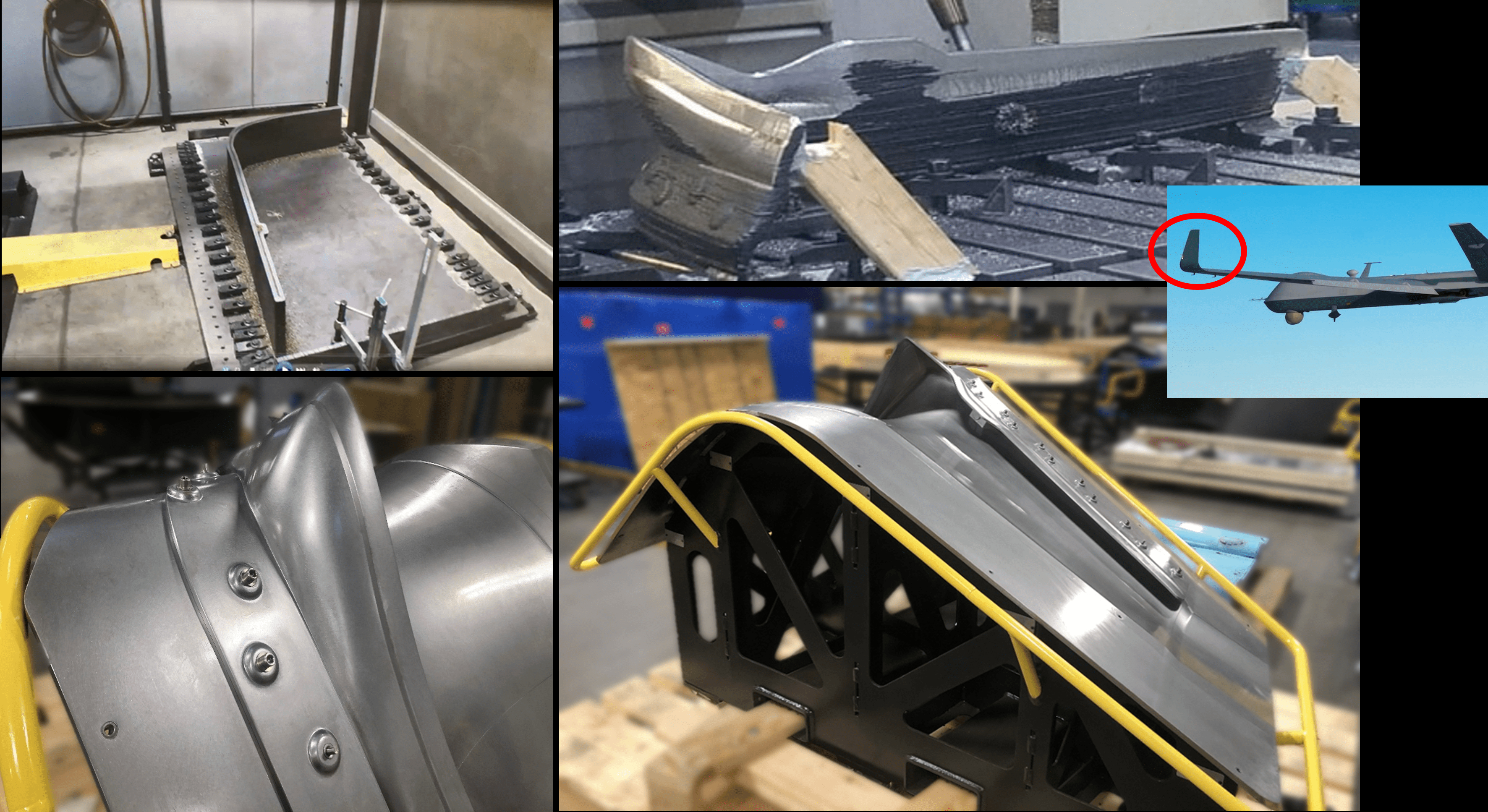
Vacuum mill fixture tools
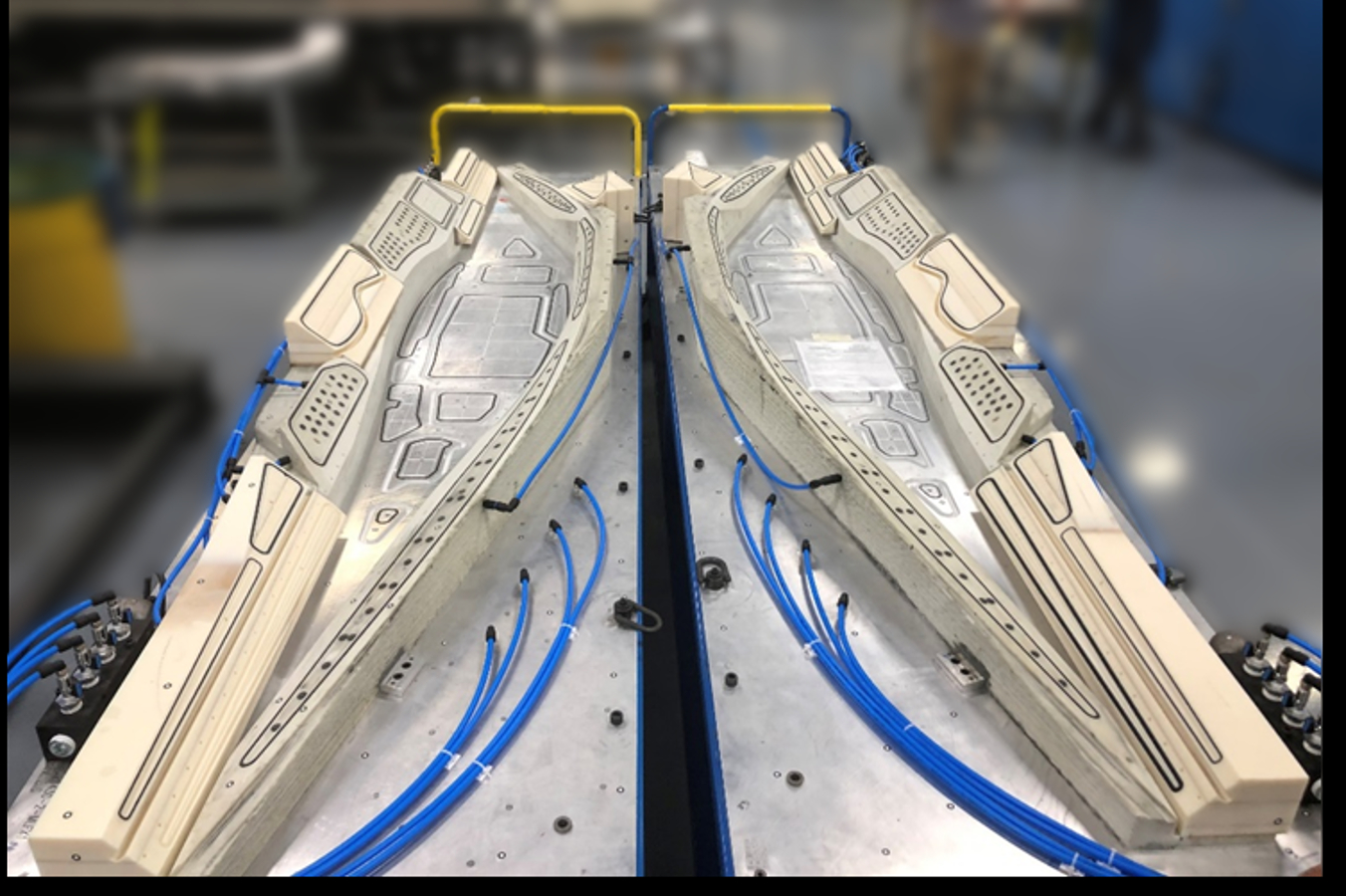
Above are left and right sides of a fairing trim fixture used to finish a small section of a UAS wing. Tooling was produced in ABS on a big area additive manufacturing (BAAM) printer. Different sections/colors in the tools represent areas that were modified from the original build, demonstrating how easily AM tooling can be altered at minimal cost.
An especially successful application area at GA-ASI is printing both small and large mill fixture tools used to verify dimensionality and hold cured composite parts at room temperature as they are drilled and trimmed to final specifications. Tooling is typically printed on large-format AM (LFAM) printers such as the large-scale additive manufacturing (LSAM) printers from Thermwood Corp. (Dale, Indiana, U.S.) or the big area additive manufacturing (BAAM) printers from Cincinnati Inc. (Harrison, Ohio, U.S.) in discontinuous carbon fiber-reinforced acrylonitrile butadiene styrene (ABS). Versus producing tooling conventionally in composite or metal, printing is 2-3 times less costly yet can be completed 3-4 times faster.
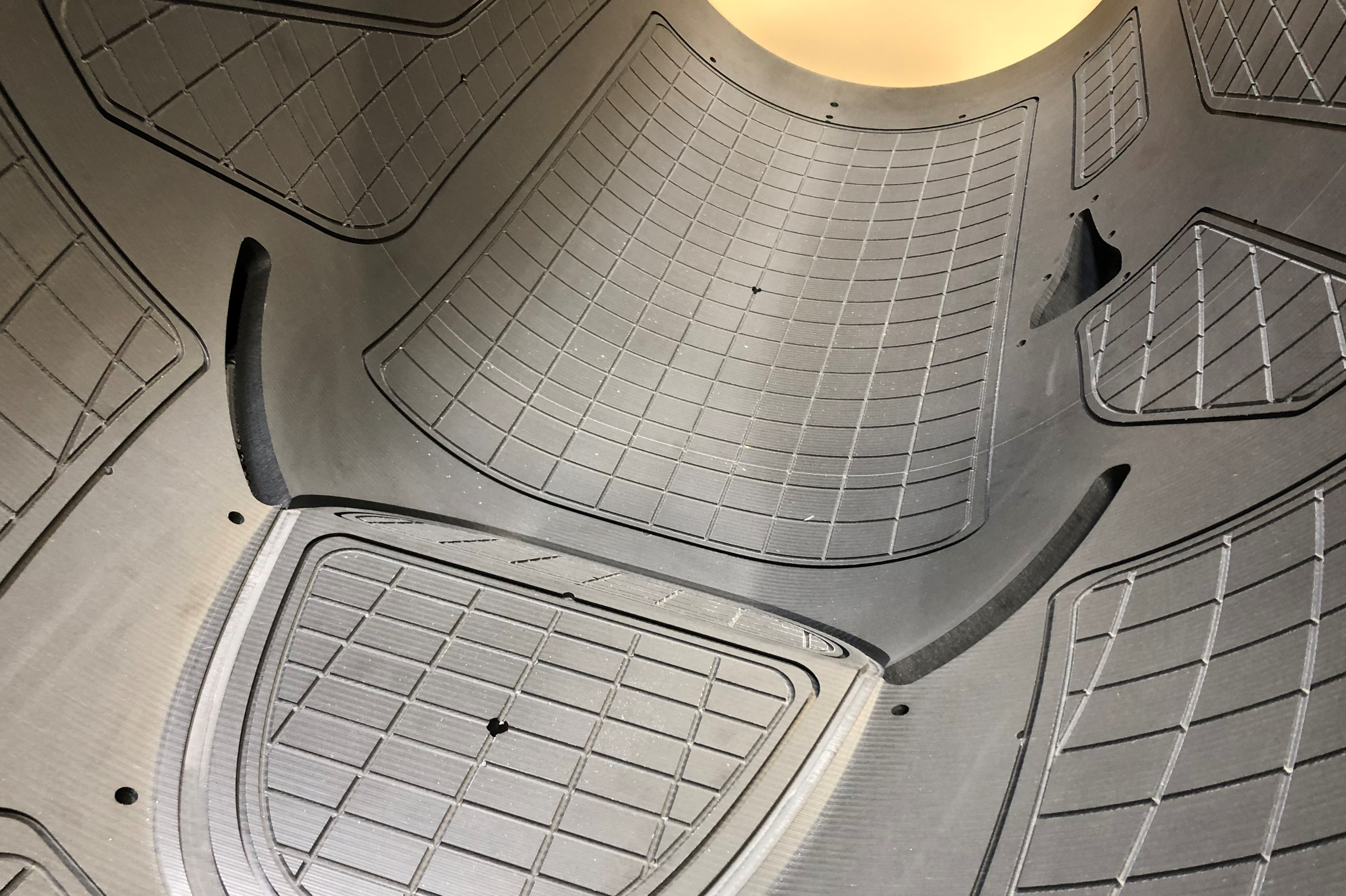
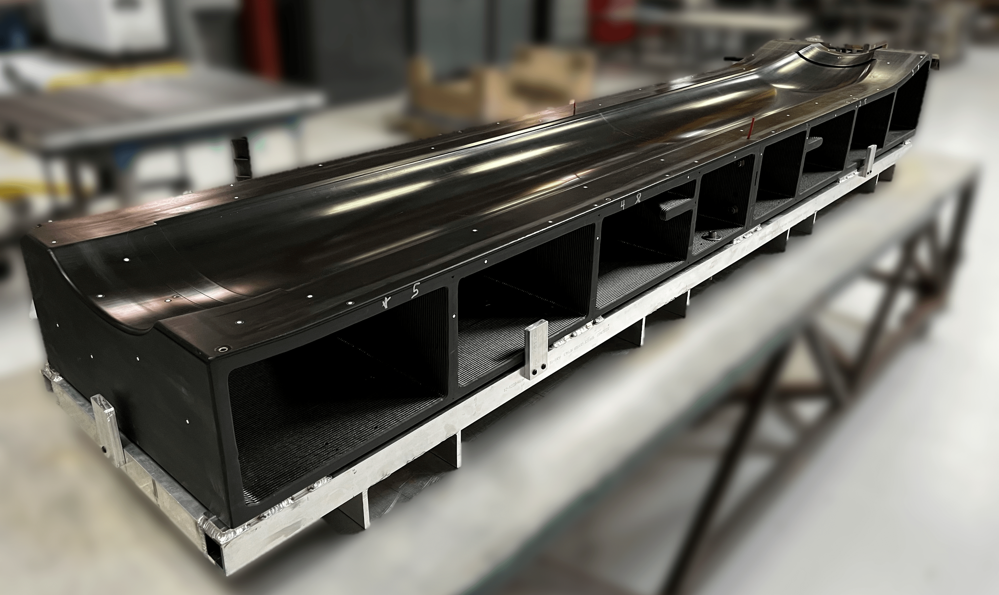
This large carbon fiber/ABS composite mill tool for an engine cowl/skin is 2.4 meters long and 1.5-1.8 meters wide. It features complex vent channels used to pull a vacuum and hold cured parts in the correct position when drilling and milling. Vent channels were CNC’d after the part was printed on the BAAM and surface finished to smooth out the bumpy surface typical of LFAM prints.
In addition to using polymer LFAM technology to print mill fixtures for composite laminate parts, GA-ASI also uses the technology to produce full-scale wind tunnel models, as well as large-scale (3.1- to 4.6-meter) end-use assemblies and medium-scale models of UAS for ground-based testing. More recently, the company qualified a low-temperature-cure lamination mold to form shallow composite facesheet parts that are planned for production in early 2024. Further out, the company expects to expand use to even larger (6.1- to 12-meter) structures to support qualified applications. One GA-ASI workaround to limitations in the build envelope with many AM technologies is a series of techniques to bond/join/weld printed metal and composite components into much larger assemblies.
Propulsion ducting and tools
Another interesting success with composite LFAM involved printing sizable tubular ducts (4.6 meters long and 1.5-1.8 meters in diameter) that were used early during propulsion system development. That early in the design process, when the propulsion system was still evolving, it didn’t make sense to lock down tooling or part designs — an approach that is both time-consuming and costly. Instead, by printing designs, the team was able to iterate faster and more freely while ensuring costs stayed low. Now that product development work is complete, an advanced composite version of the ducts is planned for 2024. The last printed duct design will be converted to a trim tool, thereby giving it a second life.
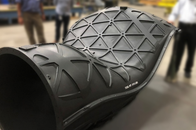
Composite LFAM has also been used early in the design process to produce ground-based propulsion system ducting. The final printed duct is planned to be reused as a trim tool for advanced composite parts.
Lamination molds
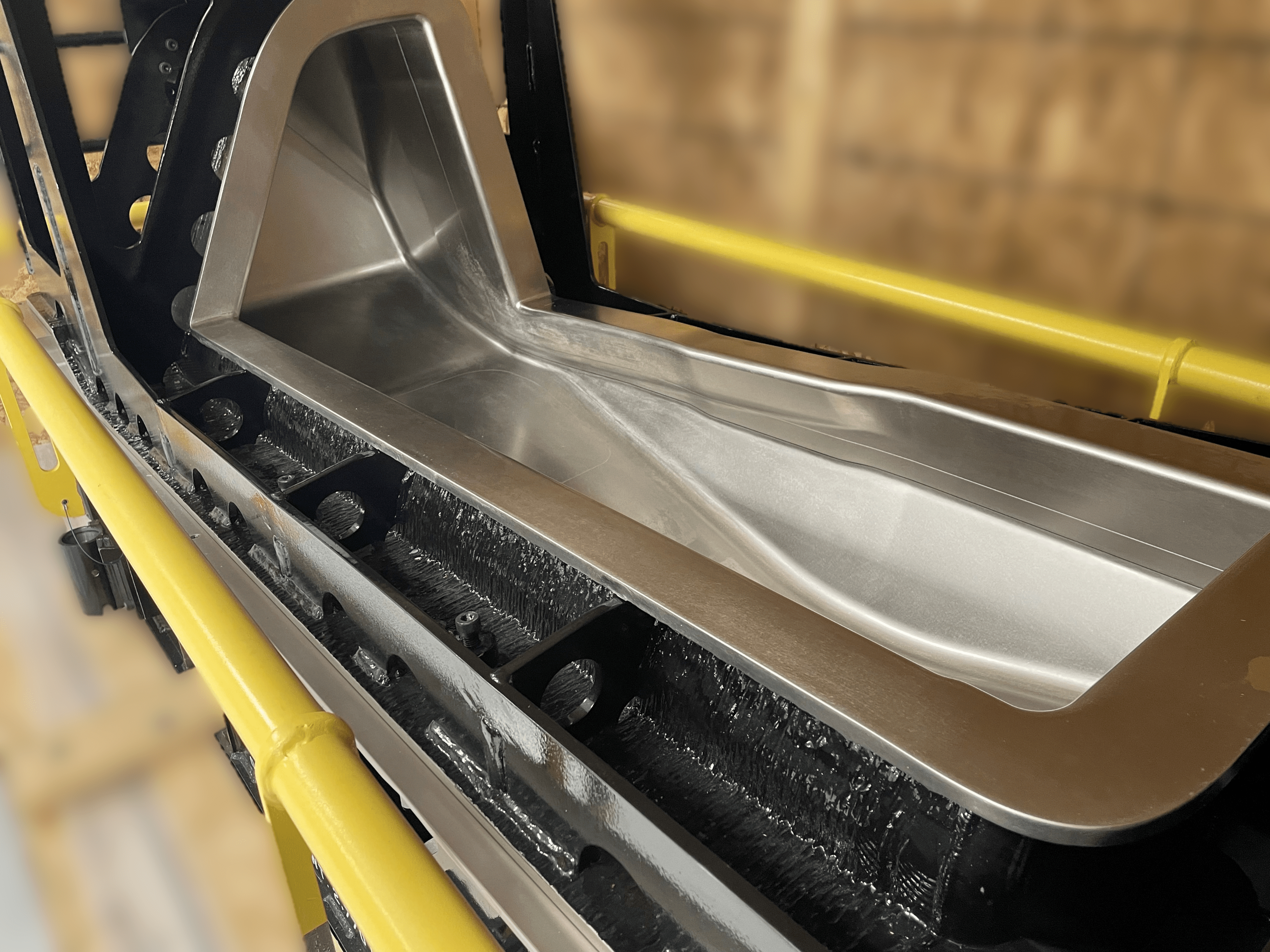
This qualified high-temperature lamination mold produced in Invar via WAAM will be used to produce composite parts for a next-generation UAS platform at GA-ASI.
Building on success with room temperature mill fixture tools, GA-ASI explored lamination molds requiring vacuum tightness and the ability to maintain tight tolerances at elevated autoclave temperatures and pressures. Metal LFAM technologies, primarily from the directed energy deposition (DED) family (including wire-arc additive manufacturing (WAAM) from Lincoln Electric Co. (Cleveland, Ohio, U.S.)), with various alloys were successfully used. (Read “Metal AM advances in composite tooling, Part 1.”)
A WAAM-printed mild-steel winglet lamination tool with challenging geometry passed all program qualifications at 30-40% less cost and 20-30% shorter lead times.
Perhaps more significant is GA-ASI’s use of composite LFAM to produce autoclave-capable lamination tooling. Polymer/composite LFAM is of interest, owing to its lower cost and lighter parts. Discontinuous fiber is typically used in polymer LFAM prints to control slumping while the thermoplastic cools and solidifies. However, that also compounds anisotropy from the printing direction. While this isn’t an issue with room temperature tooling like vacuum mill fixtures, it’s a big concern at autoclave temperatures, especially when curing large parts requiring tight tolerances. By definition, the tool expands/contracts at different ratios in X, Y and Z axes as temperature changes. Despite these challenges, GA-ASI has been successful using two different composite AM technologies.
The team printed a 4.6-meter-long composite lamination tool on the BAAM machine. Similar to the way injection moldmakers reverse engineer steel molds to solve warpage issues in thermoplastic parts — a technique called Kentucky windage — GA-ASI undersized certain tool dimensions during printing so that as the thermoplastic composite tool “grows” during autoclave ramp-up, it achieves the correct dimensions once at temperature. Fournier notes that it’s critical to use this technology for the right kind of part — ideally those with shallow curvatures and no interlocking features — and to preferentially design/print the tool so the axis with the lowest coefficient of linear thermal expansion (CLTE) coincides with the direction whose dimensions must be most tightly controlled in the final composite part.
Low-temperature composite BAAM lamination tool for a production application at GA-ASI.
Additionally, for use on LRIP tooling, GA-ASI has tested (up to 50 cycles) a ceramic matrix composite (CMC) technology widely used in the foundry industry for investment casting. Such tools are fragile in their as-printed “green state.” However, after controlled post-print infiltration (applying a chemical binder to silica sand during binder jet printing) and surface treatments, they can be densified and rendered vacuum tight. After a few curing cycles, the tool remains stable and exhibits easy surface maintenance and even a repair strategy.
GA-ASI has developed and qualified a variety of infiltration and surface processing methods to adapt the technology to high-temperature autoclave lamination tooling for aerospace. To date, more than seven infiltration and 10 surfacing processes have been tested, each with its own set of pros/cons and applicability. Of interest, the technology can produce large isotropic tools that can handle autoclave temperatures and pressures. More research is underway on this GA-ASI-developed printing technology.
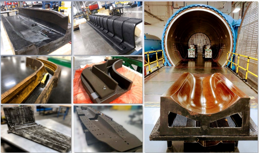
Multiple examples of binder jet printed lamination molds using sand and epoxy. Autoclave-capable lamination tools ranging from 1 to 4 meters in length are used at GA-ASI for LRIP production. Advantages are significant lead time and cost savings — from months to days — using in-house printers.
Additive takeaways
Given GA-ASI’s track record of industrializing AM technology, what advice can it offer companies considering the option?
“Before investing, ensure you understand the benefits AM can offer your business,” explains Fournier. “Recognize that AM technologies are expensive, so don’t rush into capital expenditures or try to squeeze an AM square peg into an application round hole and vice versa. Instead, establish strategic supply chain partnerships to build your ROI. Win/win partnerships with suppliers and customers are key to speeding up AM growth and adoption. Also, invest in additive manufacturing SMEs to drive your strategy and intentionally develop AM executive champions.” He notes that the faster companies focus on taking advantage of parts consolidation, complex designs and moving beyond the component level, the better the total AM value proposition becomes. He also suggests concentrating on applications featuring tight curves and conformal shapes that are costly or laborious to produce conventionally.
“If additive doesn’t bring value, it doesn’t belong there,” Fournier adds. “Start by establishing an AM ecosystem with low-criticality application families that have the highest business case to gain traction. Also, establish a centralized AM organizational structure, which for us proved to be a strong catalyst for AM adoption. After all, if no one knows about a technology, then nobody develops things for it.” He adds that industrial production AM for defense and civilian UAS is possible and it’s important to recognize that different and compounded AM benefits can be gained depending on the stage of the UAS lifecycle (see sidebar).
“However, one thing to also keep in mind is that despite its many potential benefits, AM is not the end goal,” he concludes. “Rather, AM is an enabling suite of technologies supporting full digital design and manufacturing process flows to realize significant total cost and lead time value propositions.”


.jpg;maxWidth=300;quality=90;format=webp)


Related Content

Increased molding productivity via additive manufacturing
Companies in multiple segments turn to 3D printing for end-of-arm tools, fixtures for increased safety and functionality, lower cost and faster turnaround times.
Read More
Metal AM advances in composite tooling, Part 1
Multiple metal additive technologies are gaining market acceptance and interest for composite tooling used in processes ranging from short-fiber injection to autoclave-cure prepreg.
Read More
Carbon fiber in pressure vessels for hydrogen
The emerging H2 economy drives tank development for aircraft, ships and gas transport.
Read More
Metal AM advances in composite tooling, Part 2
Toolmakers and molders continue to realize the benefits of additive versus conventional/subtractive manufacturing of molds and mold components.
Read MoreRead Next

Additive for Composites and Composites for Additive
CompositesWorld’s Jeff Sloan joins Peter Zelinski in an episode of the AM Radio podcast about how composites and 3D printing are changing one another.
Read More
Demonstrating functionalized, cost-effective composites using additive extrusion
Hybrid thermoset/thermoplastic composite part with 3D-printed functionalization demonstrates technology possibilities and EmpowerAX open platform offering expertise from members throughout the process chain.
Read More
Welding is not bonding
Discussion of the issues in our understanding of thermoplastic composite welded structures and certification of the latest materials and welding technologies for future airframes.
Read More