


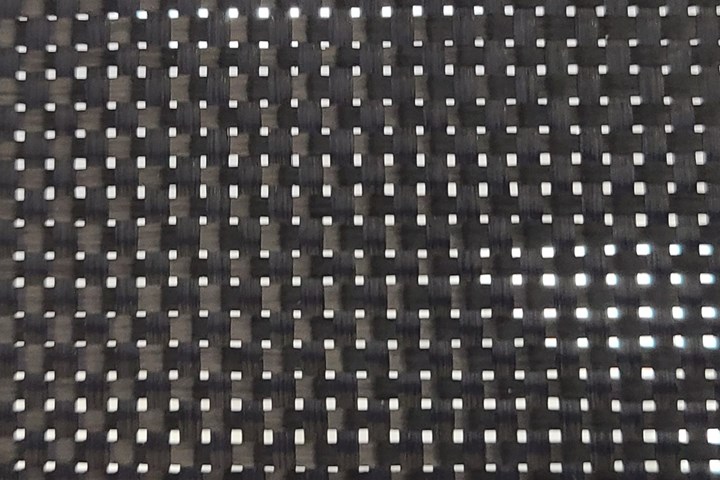
Figure 1. 3K plain weave carbon fabric held up to the light shows the open area at the intersections of the yarns that end up filled with resin or become void spaces in the laminate. Photo Credit: Abaris Training
In composites manufacturing, the ultimate objective is to produce a well-compacted laminate that has a prescribed resin-to-fiber ratio and is free of voids or flaws. Common problems in pursuit of this objective with prepreg laminates include surface porosity, voids, resin-rich areas, bridging and other flaws. These often can be attributed to problems with material selection, layup and/or bagging procedures, tooling and sometimes, design. This month I will look at factors that contribute to these problems and explore methods to mitigate them.
Effect of fabric forms
Plain weave fabric surfaces are the worst offenders, but not the only fabric form that is prone to surface porosity. 3K plain weave carbon fiber fabric looks like flyscreen (Fig. 1). The sites at the intersections are inherently open spaces until coated with resin in the prepregging process. If this resin is later pulled away from these sites, a void or porous area emerges. Fig. 2 illustrates two different types of fabric surfaces and the contrast in void size between two fabric forms. This is an example of how designing with an alternate fabric form could greatly minimize surface porosity.


Honeycomb sandwich panels
In a cocured process, the capillary action of honeycomb core under vacuum or pressure tends to move resin from the surface plies toward the core, thus resulting in a porous surface condition adjacent to each core cell. Added adhesive at the skin-to-core interface may help reduce porosity but at a significant weight penalty to the structure.
This is especially true with 2-4 ply skins of plain weave fabric where there is very little extra resin present (~40% volume fraction). Instead of continuously reworking these surfaces, the solution can be as simple as adding an ultralight syntactic surface-ply1 layer to the design. The weight penalty is far less than additional adhesive, and risks are minimal compared to the effort, cost and time of reworking porous surfaces. Care must also be taken during any vacuum bag compaction step (debulk) to maintain resin content in skin plies prior to core installation.
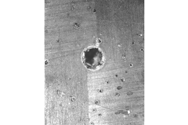
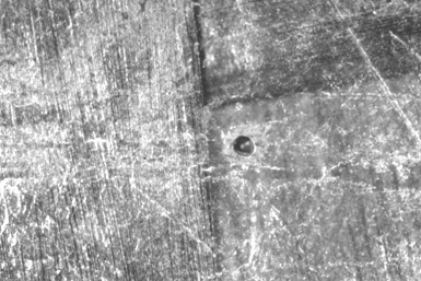
Figure 2. Above: Microphoto of a small void (porosity) at the intersection of the 3K carbon yarns at the laminate surface. Take note of the satellite “pits” around the void. Bottom: Same scale microphoto of a much smaller void inherent to a 6K 5HS fabric surface. Photo Credit: Abaris Training
Molding considerations
Mostly ignored by many composites fabricators is the fact that surface porosity may be related to very-low surface energy (SE) of the released mold surface, causing resin to repel instead of wetting the surface, resulting in unwanted or excessive porosity. This can be alleviated by choosing an “adjustable” release system with a higher SE that enables wetting but still ensures release from the mold surface.
If porosity is repeatedly found in a specific area of the part, it may be due to a diffuse leak in the mold adjacent to the defect area. This requires further assessment of the mold and repair or replacement. A randomly located porous area that fans out from an edge is likely from a leak in the bag (or pleat) which can easily be remedied with better bag sealing.
Another issue is low heat-transfer rate of (metal) tooling, where bagside plies begin to gel while tool-surface plies are just becoming active, resulting in trapped air or gas at the surface. Adding an extended dwell under vacuum only to the cure recipe could solve the problem.
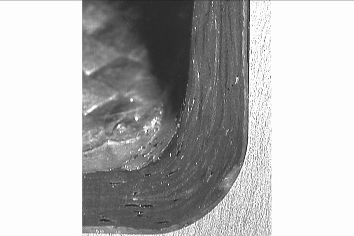
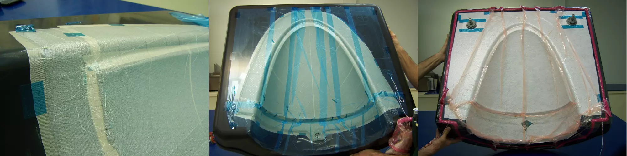
Figure 3. Voids in corner due to bridging of plies and/or ancillaries used during layup and processing. Photo Credit: Abaris Training
Corner and barrel bridging
Surface porosity and voids may also appear in small radii or larger convex areas of a part (concave in the mold) where bridging occurs in the corners (Fig. 3.), or where plies span across valleys in the mold (barrel bridging). The lack of localized compaction and creation of low-pressure areas (LPAs) between plies results in either resin-rich areas or voids in the laminate. Mitigation of these defects requires careful examination of the ply size, placement methods and number of debulks. It is also necessary to always tailor peel ply, film and breather layers, and to ensure there is enough bag film (pleats) to allow everything to compact during debulks and cure (Fig. 4).

Figure 4. All materials are tailored to allow for compaction in corners and in the valley of this part: Peel ply (left) is carefully tailored and secured, film layer (center) is pleated and vacuum bag film (right) is well pleated to allow for compaction of the underlying laminate. Photo Credit: Abaris Training
It is a mistake to think that autoclave pressure will overcome bridging defects. For example, consider that typical autoclave pressure is 45-100 psi, while standard modulus carbon fiber tensile strength is ~660 psi.
Evolving gases during cure
Production of gas in a laminate during cure is not uncommon and can produce problematic voids, but the gas mitigation strategy you use depends on the source of the gas. Expanding gas from moisture in a prepreg layup can often be alleviated by simply debulking for longer periods of time prior to cure. However, the development of gas from chemical reactions occurring in the resin during cure is more difficult to mitigate. Unlike epoxies, imides, phenolics and polybenzoxazines produce gas byproducts and thus require a more in-depth understanding of these reactions to resolve them.
A thermogravimetric analysis (TGA) of the prepreg resin can be used to identify weight change at specific temperatures that correlate with the evolution of gas. Using this data, you can adjust the cure recipe to change ramp rates and isothermal dwells to allow time for the gas to evolve and find a route out of the laminate. Corresponding adjustments to vacuum and pressure steps will then permit time for the gas to evacuate or convert back into the solution (Fig. 5).
New material developments
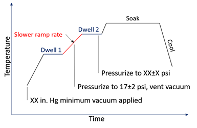
Figure 5. Modified autoclave cure recipe with additional isothermal dwells, adjusted ramp rate between dwells and modified vacuum and pressure steps to permit time for removal of evolving gases. Photo Credit: Abaris Training
Traditionally, out-of-autoclave (OOA)-friendly fabrics are resin-coated on one side — the other side is dry — to provide an internal route for air and gas to escape during processing. Apogee Composites (Los Angeles, Calif., U.S.) recently introduced through-thickness permeable prepreg (TTPP) that has uniform open spacing in the resin film itself (i.e., creating dry fiber LPAs) that allows the laminate to infuse internally (Fig. 6). More developments like this will lead to materials that inherently produce low void laminates.
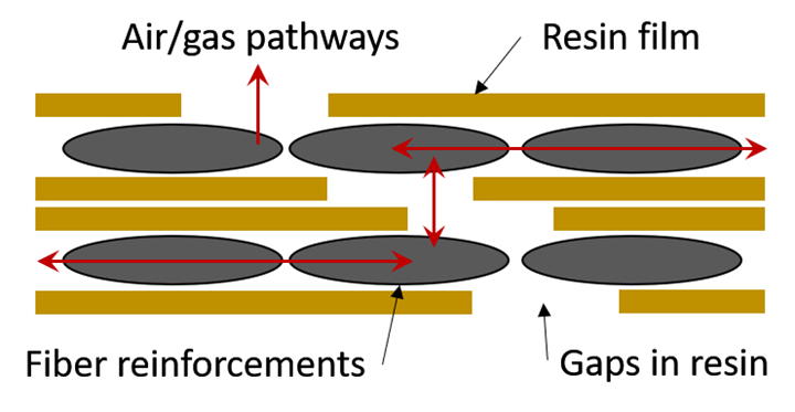
Figure 6. Uniform gaps in resin film layers of prepreg plies allow for through-thickness permeability and air/gas evacuation. Photo Credit: Apogee Composites
Transforming modifications into best practices
It is recommended that engineers and technicians take a systematic approach to troubleshooting these issues, first by exploring easy modifications to layup, debulk and bagging operations prior to taking on more complex changes such as adjusting the cure recipe or adding new materials, which ultimately may require changes to the design and/or material and process specifications. In the future, designers are encouraged to explore using fabric forms and new materials that are best suited for the applicable process. Methodical attention to detail now surely will bring about good results that can be turned into best practices that can be repeated on the shop floor.
1. Ultralightweight syntactic surface ply materials are available from 3M, Henkel-Loctite, Solvay, Toray and other prepreg manufacturers. They can be purchased with or without expanded foil (mesh) lighting strike protection (LSP) embedded in the layer. Densities vary but are normally between 0.08-1.3 grams per cubic centimeter.


Related Content

PEEK vs. PEKK vs. PAEK and continuous compression molding
Suppliers of thermoplastics and carbon fiber chime in regarding PEEK vs. PEKK, and now PAEK, as well as in-situ consolidation — the supply chain for thermoplastic tape composites continues to evolve.
Read More
DLR completes MFFD upper shell skin layup
Eight-meter-long CFRTP fuselage skin was achieved via laser-heated in-situ consolidation, with stringers, frames and cleats to be welded.
Read More
Metal AM advances in composite tooling, Part 1
Multiple metal additive technologies are gaining market acceptance and interest for composite tooling used in processes ranging from short-fiber injection to autoclave-cure prepreg.
Read More
Composite prepreg tack testing
A recently standardized prepreg tack test method has been developed for use in material selection, quality control and adjusting cure process parameters for automated layup processes.
Read MoreRead Next

Troubleshooting failures in adhesive-bonded composite joints
Cause of adhesive bonding inconsistencies or failure may be numerous. According to Louis Dorworth, the following points should be examined to determine the culprit.
Read More
CW’s 2024 Top Shops survey offers new approach to benchmarking
Respondents that complete the survey by April 30, 2024, have the chance to be recognized as an honoree.
Read More
Composites end markets: Energy (2024)
Composites are used widely in oil/gas, wind and other renewable energy applications. Despite market challenges, growth potential and innovation for composites continue.
Read More