


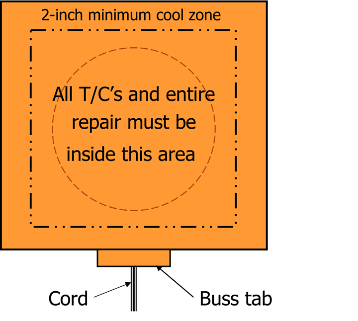
Fig 1. The repair patch, caul plate and all TCs/sensors must be within the effective area of the heat blanket for thermal viability. Photo Credit: Abaris
It is possible to cure composite repairs locally on the damaged structure, outside of an oven or autoclave environment. Typically, this repair method uses a heat blanket, a temperature controller and thermocouples (TCs) or other temperature sensors to measure and control temperature to a prescribed cure recipe. This works well on simple geometries, but there can be issues in cases where the configuration is complex, or where tight radii are involved. For example, a conventional heat blanket may not conform completely and can cause bridging or wrinkles in the adjacent repair patch. In this circumstance, other heat sources might be employed as an option. In CW’s Dec. 2021 issue, “A second look at cobonded tapered scarf repairs for composite structures,” we studied repairing composite structures via scarf repair. This month, we examine the use of heat blankets and other heat sources to cure composite repairs.
Heat blankets
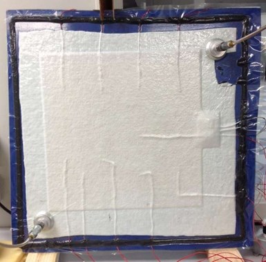
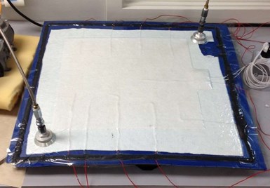
Fig. 2. The panel shown has hat-section stiffeners on the backside causing heat sinks within the structure. Testing was done both in the vertical (top) and horizontal (bottom) planes at 250°F (122°C). The results are shown in Table 1 (below). Photo Credit: Heatcon Composite Systems Inc. (Seattle, Wash., U.S.).
Typical 120-volt, 5W/in² nichrome wire, glass-reinforced silicone heat blankets will work for small- to medium-size repairs (≤4 square feet/0.38 square meter) on flat or gently contoured surfaces. The rule of thumb is to size the blanket so that it exceeds the repair patch and all TCs or sensors by a minimum 2-inch (51-millimeter) distance all around (Fig. 1). For larger areas, 240-volt and 440-volt blankets can be used but require a higher voltage/amperage power source. It may also be more difficult to maintain temperature uniformity as the size of the blanket increases. In some cases, it may be more efficient to use two heat blankets that are overlapped by 4 inches (102 millimeters) and controlled using two zones of the hot bonder.


Temperature uniformity of a heat blanket during a cure cycle depends on the thermal uniformity of the underlying structure that is being repaired, along with proper location of the TCs or sensors used to monitor and control the repair. Stiffeners, frames or metal components adjacent to the repair, could present heat sinks that need to be addressed. Although an aluminum caul plate under the heat blanket can go a long way towards distributing heat to the repair itself, an additional heat source or insulation may be necessary to heat or insulate the heat sinks in the structure. Another consideration is that a blanket placed vertically on a structure may have a thermal gradient from top (hotter) to bottom (cooler) due to convective heating effects. This can be mitigated with carefully placed insulation or by using a Smart Susceptor heat system1 that can adjust to provide thermal uniformity. Reference Fig. 2 and Table 1 for a comparison between horizontal and vertical positions.
|
Table 1 |
||||
|
Blanket Type |
Dwell Setpoint |
Hottest TC |
Coldest TC |
Delta T |
|
Resistive 5WSI Horizontal |
250°F (121°C) |
261°F (127°C) |
239°F (115°C) |
22°F (12°C) |
|
Smart Susceptor Horizontal |
250°F (121°C) |
253°F (123°C) |
247°F (119°C) |
7°F (4°C) |
|
Resistive 5WSI Vertical |
250°F (121°C) |
267°F (131°C) |
239°F (115°C) |
28°F (16°C) |
|
Smart Susceptor Vertical |
250°F (121°C) |
255°F (124°C) |
246°F (119°C) |
9°F (5°C) |
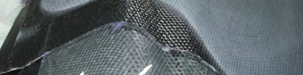
Custom-made, stretchable heat blankets are also available. Custom blankets are usually prescribed for complex shapes that are repaired repeatedly (e.g., radomes or hat-section stiffeners). However, even stretchable blankets are unable to conform into tight radii, or facilitate sharp multi-angle intersections or outside corner shapes where thermal expansion of the unreinforced silicone blanket (even under vacuum bag pressure) may promote defects in the underlying repair (i.e., compound core ramp angles or leading-edge repairs on an airfoil shape, Fig. 3).
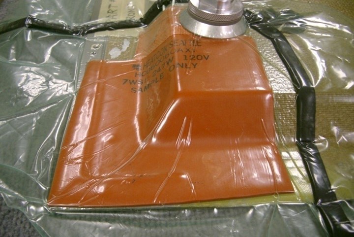
Fig. 3. This heat blanket looks to conform well, but on further investigation, it is found to be bridging along the inside corner radii, especially on the 60° core ramp angle to flange, facing the camera. Photo Credit: Abaris
Heat lamps
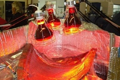
Fig. 4. Reflective materials can be placed around the setup to direct and help retain heat. Carbon fabric is used as a breather under the bag to absorb and transfer heat to the underlying repair. Photo Credit: Abaris
Conventional heat lamps (bulbs) produce a concentric thermal gradient across the target area that runs from the hotter central focal point of the beam to the cooler outer edges. An array of lamps at a prescribed distance is typically deployed, arranged with reflective material around the lamps or the setup (Fig. 4). Additionally, an aluminum caul plate on a flat or gently contoured surface with carefully placed TCs/sensors (at the hottest focal points), and a layer of carbon fabric (or black paint on the bag film) can be placed over the repair to help absorb heat. This will enhance temperature uniformity over the repair area. It is never recommended to use heat lamps without a controller, for temperatures exceeding 180°F (82°C) or for repairs over 1 square foot (0.09 square meter) of area. Curing larger
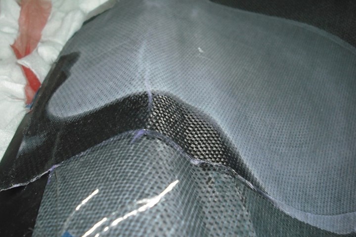
Fig. 5. It is easy to see the cured areas (gray) versus the uncured areas (black) in this image of a prepreg repair on a complex surface geometry. Photo Credit: Abaris
Radiant infrared heater array
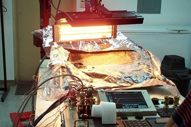
Fig. 6. This heater array is positioned to heat a curved area of a CFRP panel that has been repaired. Aluminum foil reflectors keep it from overheating the part. Eight or more thermocouples are used to control and monitor the repair and surrounding areas.
The challenge with this heating method, much like with heat lamps, is attaining thermal uniformity at the local repair site. Environmental factors such as a cross-breeze or proximity to air conditioning can wreak havoc with these methods. Also, because heat elements are linear rather than circular, hot spots will line up with the elements when the array is placed too close or lose heat energy as the lamps are moved too far away from the repair site — the distance must be just right to achieve the desired temperature where it is needed. Reflective material can be used to direct heat towards the repair area or to protect the surrounding structure by reflecting heat energy away. Many of the same tricks used with heat lamps can be deployed with this heating method to improve heat absorbance, heat transfer and temperature measurements in and around the repair area. Successful cure cycles of ≤260°F (127°C) have been achieved on flat and gently contoured surfaces, limited in area by the size and shape of the array, but in general, for areas no greater than 3 square feet (0.28 square meter). See Fig. 6 for setup.
Hot air machine
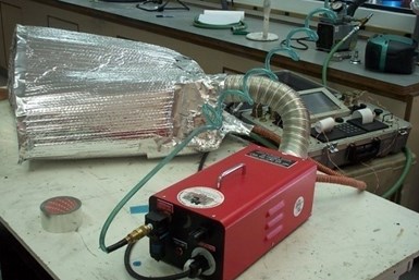
Fig. 7. This hot air machine (red) is used with a makeshift oven made with aluminum hot water tank wrap. This wrap can be used to fabricate any oven- or tent-like shape with aluminum speed tape to heat a local repair or entire part. The flexible hose goes to a heat diffuser tube located inside the tent with a hot air exchange hose (red) that recycles hot air. Compressed air (green hose) drives the air supply to heat elements located inside the machine. Photo Credit: Abaris
Driven by a compressed air source, a hot-air machine is more useful than other localized heat sources for heating complex shapes. It works by fabricating a makeshift “oven” or “tent” over the repair area and then using convective heat transfer to heat the air inside. Heat transfer from the air to the repair site initially requires hotter air temperatures and care must be taken not to overheat the surrounding structure. It is recommended that a set of controlling TCs/sensors be used at the repair site and that others be used to monitor air and part temperatures elsewhere. The tent design should allow for uniform airflow across the repair area while avoiding concentrated hot spots. Creating small “vents” in the tent, opposite the air diffuser, can help direct and uniformly distribute the hot air. Locating a return hose at the furthest point from the hot air inlet, feeding hot air back into the machine, is required to efficiently maintain temperature during cure. See Fig. 7 for setup.
Dependent upon the thermal mass and complexity of the structure being heated, 120-volt equipment is effective for cure temperatures up to 260°F (127°C) while 240 volts is effective up to 350°F (177°C), each for a volume area of approximately 24 cubic feet (0.68 cubic meter).
Takeaways
To successfully use an alternative heat source, the operator must be aware of the thermal dynamics at play and how to effectively manage heat transfer from the heat source to the repair without adversely affecting the surrounding structure. Measuring temperature is at the heart of this and is key to efficacious processing. Applying the techniques presented here requires training and continuous practice. Learning the hard way can be costly. Alternatively, applying knowledge to practice can result in high-quality composite repairs outside of an oven or autoclave.
References
1. Smart Susceptor from Heatcon Composite Systems Inc., Seattle, Wash., U.S. (https://www.heatcon.com/product/hcs9400-02-smart-susceptor/)


.jpg;maxWidth=300;quality=90;format=webp)
Related Content

Developing repairs for thermoplastic composite aerostructures
HyPatchRepair project proves feasibility of automated process chain for welded thermoplastic composite patch repairs.
Read More
CompPair adapts HealTech composites to LCM processes
The new system, demonstrated through the manufacture of a large-scale wind turbine blade section, enables the repair and recovery of infused composite structures within minutes.
Read More
Modec, Toray jointly develop FPSO, FSO repair solution using CFRP patches
CFRP patch technology will target localized pitting corrosion repairs for floating vessels used by the oil and gas industry, leading to minimal disruption and more streamlined repair.
Read More
TPRC research project investigates thermoplastic composite structure repair strategies
Linda Grafen’s two-year study explored reconsolidation and patch repair methods to determine their feasibility for impact damage repairing.
Read MoreRead Next

A second look at cobonded tapered scarf repairs for composite structures
Composites repairs, such as cobonded tapered scarf repairs, seek to sufficiently restore structural loads so that components perform without failure
Read More
Composites end markets: Energy (2024)
Composites are used widely in oil/gas, wind and other renewable energy applications. Despite market challenges, growth potential and innovation for composites continue.
Read More
CW’s 2024 Top Shops survey offers new approach to benchmarking
Respondents that complete the survey by April 30, 2024, have the chance to be recognized as an honoree.
Read More