


Photo credit: ThermoPlastic composite Research Center (TPRC)
Note: Information and images for this article were obtained from the course “Advanced Forming of Thermoplastic Composites” taught by the ThermoPlastic composite Research Center (TPRC).
Thermoplastic composites (TPCs) first gained advantage with the demand for faster production rates in aerospace and other lightweight applications. Part production in a matter of minutes made thermoforming (also known as stamping) the most common thermoplastic composites process and the first to mass produce flying parts (see “Inside a thermoplastic composites hotbed” and “Thermoplastic composites clip time …”).


The process begins with a blank — a preconsolidated thermoplastic composite laminate with the required ply orientation — and comprises the following steps (Fig. 1): Blank preparation (cutting and fixation), blank heating, transfer to mold, blank positioning, forming, cooling, demolding of the part and trimming/finishing. The thermoforming process is a simple concept but involves complexities and challenges that should be addressed to achieve repeatable, high-quality composite parts.
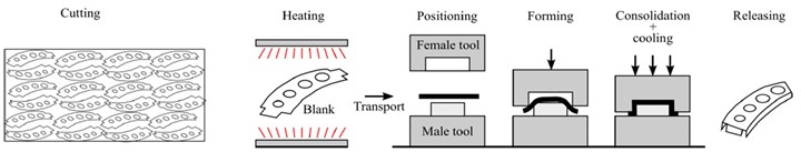
Fig. 1. Steps in thermoforming of thermoplastic composites. Photo credit: TPRC
Avoiding wrinkles
A wrinkle is a visual and functional defect. It can be described as an out-of-plane bending of the material. The main cause is insufficient shear deformations, such as interply slip and intraply shear, during processing. Wrinkling occurs predominantly in doubly curved surfaces. Consider the following actions to minimize wrinkles.
Sufficient pre-heating and fast transfer. During forming of the blank, temperature should remain above the melt temperature (Tm) of the TPC matrix to allow shear deformation. Take into account that during transfer from the pre-heating stage to the mold, the temperature can drop significantly — possibly as much as 40-50°C in three seconds. Thus, preheating should be high enough that the polymer will remain above Tm — or glass transition temperature (Tg) for amorphous polymers — after transfer and during forming. A cold blank will not deform properly and will develop wrinkles. However, beware not to overheat the blank to avoid polymer degradation.
Fabric weave style and layup. Harness-satin (HS) fabrics have better drapability due to easier in-plane shear deformation, which helps to prevent wrinkles. Drapability of woven fabrics, from highest to lowest, is as follows: 8HS > 5HS > 2 x 2 twill > plain weave. 5HS fabric is often a good starting point because it balances drapability and mechanical performance. Blanks made using unidirectional (UD) reinforcements tend to wrinkle more than HS fabrics due to high friction between the fibers which resists in-plane shearing. Allowing in-plane shear is the key to success with forming of UD blanks, especially with doubly curved surfaces.
Ply orientations such as [0, 90, ±45]s found in a quasi-isotropic layup can inhibit shear deformation, which enhances wrinkles. Alternatively, cross-ply (e.g., [0, 90]) layups will help prevent wrinkling because shearing is not restricted by other plies.
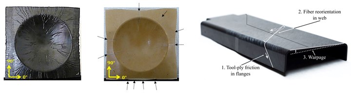
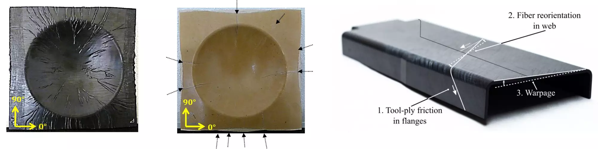
Fig. 2. Avoiding wrinkles and warpage
The hemispherical part shows many small and large wrinkles using a UD blank (left), while only large wrinkles are visible using an 8HS blank (right). Warpage in this composite spar resulted from fiber reorientation due to tool-ply friction in the flanges. Photo credit: “Forming limits of thermoplastic composites” by D.J. Wolthuizen, et. al. (left) and “Rapid manufacturing of tailored thermoplastic composites by automated lay-up and stamp forming” by Tjitse K. Slange (right).
Blank preparation and fixation. Grippers and tensioners can be used to hold the blank in tension in areas that are prone to out-of-plane bending. Finding the optimized configuration might be time-consuming, with multiple iterations required, but using process simulation software helps. Proper blank tensioning also prevents the blank from sagging, which can cause issues during transfer and forming. Such issues include the blank touching the mold too soon, which might place too much material on the mold before draping can occur, resulting in buckling and wrinkling. The blank may also sag and touch the heater, which can cause damage to the blank or stop the process.
Optimizing the blank’s final geometry and cutting it to a near-net shape can prevent wrinkles and reduce scrap. Cuts and darts can also help to prevent out-of-plane bending by reducing fiber stresses to allow better forming.
Overcoming challenges with mold design
During thermoforming and similar molding processes, the mold itself can present challenges. Proper mold design can help head off issues with mold costs, heating, part defects and demolding.
Mold tool materials. To choose the right material for a thermoforming tool, consider the materials used for the final part, as these will affect the required mold temperature (Tmold). For example, following the rule of thumb Tmold =(Tm+Tg)/2, a part made of reinforced PPS (polyphenylene sulfide Tm = 280°C) will require a Tmold of approximately 180°C. (Amorphous and semi-crystalline thermoplastic polymers have a Tg, but semi-crystalline polymers also have a Tm.) A metal mold is thus required to conduct sufficient heat from the platen of the heated press or a heated tool for molding of the part. Conduction is also necessary for efficient part cooling. However, for a part made using a reinforced PMMA (polymethyl methacrylate), which has a much lower Tg (~100°C), a wooden or epoxy tool at room temperature might be sufficient.
Other considerations include the current development phase and available budget, but also the number of parts to be manufactured from the tool. During processing, mold tools are exposed to friction, high temperature and pressure. Because wood and epoxy have lower heat resistance and load-carrying capability compared to metals, molds made from these materials will have a shorter lifetime and are more suitable for small-volume production, while metal tools will be preferred for high-volume production.
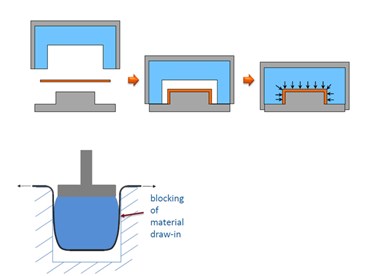
Fig. 3. Metal-rubber tools
Metal-rubber tools use rubber on one side (blue) and metal on the other to apply continuous hydrostatic pressure. However, using rubber on the male side of the tool can allow expansion during pressing (bottom image), blocking material draw-in. Photo credit: TPRC (top) and Valeria Antonelli, “Improvements of thermoforming of thermoplastic composites using a collection of rubber particles as a soft mould half,” TU Delft (bottom).
Another material system to consider for tooling is metal-rubber, where one half of a matched set is metal and the other is rubber. This allows production flexibility and can be used for parts with larger tolerances. A metal-rubber tool also provides uniform hydrostatic pressure, which is beneficial in flange areas and in blanks with thickness variations, typical of tailored blanks made with multiple UD plies.
This inherent application of hydrostatic pressure is also an advantage when the same part is produced at multiple different thicknesses, eliminating the cost of separate molds for each thickness. When designing a metal-rubber tool, it is important to also consider the following disadvantages and challenges:
- The metal side of the tool will produce a smoother finish vs. the rubber.
- Metal-rubber tools will have an order of magnitude higher coefficient of thermal expansion (CTE) vs. all-metal tools.
- Due to lower thermal conductivity vs. metal, cooling will take a bit longer and create more of a lag in temperature control response.
- Increased wear and aging will result in a shorter service life vs. all-metal tools.
Forming and demolding. Proper mold design ensures sufficient pressure, optimal draping, helps prevent defects and promotes safe part removal. Though there are many issues regarding forming and demolding, several of the most important include:
- Pressure. During thermoforming, low pressure may lead to poor consolidation, reduced mechanical properties and out-of-tolerance part dimensions. For a matched metal-metal tool, eliminate end stops so that the continuous pressure on the laminate is not prevented by the gap the end stops create.
- Allowing material draw-in. To avoid expansion of the rubber side of the mold during pressing (known as barreling), which may block movement of the material during pressing (draw-in), place the rubber on the female side of the molding tool (see Fig. 3).
- Part removal. For L-shaped parts, design the mold with the desired L angle tilted to a V, which will reduce friction with the tool and allow easy part removal. For box-shaped parts, use a draft angle of 1-2 degrees for each side; higher angles may be needed for deeper parts.
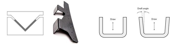
Fig. 4. Tooling considerations
To facilitate demolding, tooling for L-shaped parts can be tilted and tools for box-shaped parts should include a draft angle. Photo credit: Bracket from Dutch Thermoplastic Composites
Warpage and spring-in
Warpage and spring-in are shape distortions caused by anisotropic material properties and uneven resin cooling that occur after the part is molded and can lead to out-of-tolerance part dimensions, which might lead to problems with assembly and cause parts to be scrapped. Warpage occurs when a region of high molded-in stress within a part intersects with a region of low molded-in stress. That stress imbalance is relieved by the high-stress region distorting the low-stress region, resulting in bowing or twisting of the laminate.
Spring-in occurs in curved panels or in parts with corner sections when molded-in stress causes wall sections to distort inward at an angle less than the as-designed angle. This often happens in fiber-reinforced composites because of their anisotropic properties. Part geometry is also a factor. Differential shrinkage between in-plane (low CTE in the fiber direction) and through-thickness (high CTE of the matrix), can cause an angle decrease of 1-3 degrees.
Addressing shape distortions can be costly and time-consuming. Using simulation and design tools is highly recommended for faster part development. Look for the following possible causes and fixes when facing warpage:
- Process parameters. Mold temperature affects through-thickness properties associated with crystallization and viscoelastic effects, which may affect warpage. Reducing mold temperature can reduce spring-in but increase internal stresses, which may lead to spring-in once released. This uncertainty should be carefully examined. High pressure and forming speed can also reduce spring-in and possibly promote the opposite problem — spring-back — by limiting interply slip. Increasing dwell time can ensure the matrix is fully solidified and eliminate residual heat, which reduces shrinkage after part removal, and thus, spring-in.
- Mold design. Compensating for spring-in can be done by changing wall angles in the mold. Also, as mentioned, metal molds promote more uniform cooling and can help reduce risk of warpage, especially in thick parts.
- Layup. Symmetric layups are commonly used to mitigate warpage, but during thermoforming, fiber re-orientation can occur, leading to asymmetry and warpage. Another manifestation of asymmetry is resin migration during radius forming (including corners). This causes fiber redistribution and local changes in fiber volume fraction which promotes anisotropy and warpage. Different layups and layup sequences behave differently as fibers respond to stresses which, in turn, affects warpage. Simulation and prediction tools can help to address this complex material behavior.
Although the thermoforming/stamping process involves multiple parameters and complex material behaviors, there are basic principles and actions that can guide successful development. With increasing implementation of thermoformed TPC parts, and particularly UD tailored blanks, new challenges are being addressed with innovative solutions and improved design/simulation tools.
About the Author

Yehiel Shaham
Yehiel Shaham is a plastics and polymers engineer with nearly 12 years of experience in development and manufacturing of thermoplastics from leading Israeli plastics and defense companies. During 2016-2020, he was the thermoplastic composites (TPCs) lead engineer in RAFAEL, where he specialized in TP-AFP. Currently, he is aiming to promote TPCs in Israeli industry.


.jpg;maxWidth=300;quality=90;format=webp)


Related Content

Demonstrating composite LH2 tanks for commercial aircraft
Toray Advanced Composites and NLR discuss the Netherlands consortium and its 4-year project to build demonstrator liquid hydrogen tanks, focusing on thermoset and thermoplastic composites.
Read More
Materials & Processes: Resin matrices for composites
The matrix binds the fiber reinforcement, gives the composite component its shape and determines its surface quality. A composite matrix may be a polymer, ceramic, metal or carbon. Here’s a guide to selection.
Read More
The potential for thermoplastic composite nacelles
Collins Aerospace draws on global team, decades of experience to demonstrate large, curved AFP and welded structures for the next generation of aircraft.
Read More
Protecting EV motors more efficiently
Motors for electric vehicles are expected to benefit from Trelleborg’s thermoplastic composite rotor sleeve design, which advances materials and processes to produce a lightweight, energy-efficient component.
Read MoreRead Next

Challenges of laser-assisted tape winding of thermoplastic composites
Practical solutions for process-related challenges in LATW, which has great potential for pressure vessels and storage tanks.
Read More
CW’s 2024 Top Shops survey offers new approach to benchmarking
Respondents that complete the survey by April 30, 2024, have the chance to be recognized as an honoree.
Read More
From the CW Archives: The tale of the thermoplastic cryotank
In 2006, guest columnist Bob Hartunian related the story of his efforts two decades prior, while at McDonnell Douglas, to develop a thermoplastic composite crytank for hydrogen storage. He learned a lot of lessons.
Read More