
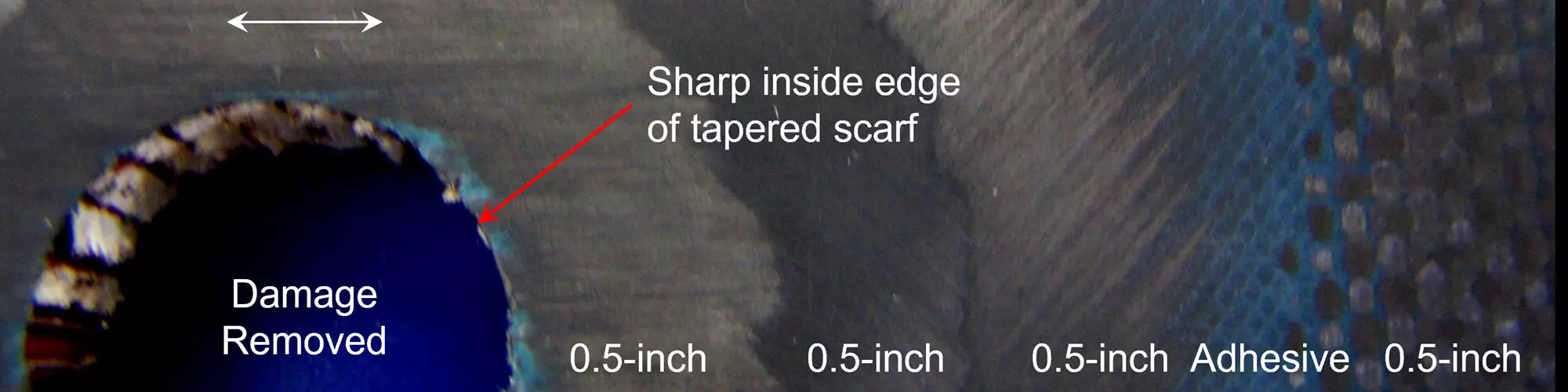


Fig. 1. Hand-machined scarf through three plies of CF unidirectional (UD) tape and one ply of CF plain woven fabric at 0.5-inch (nominal) distance per ply. Note the small amount of breakthrough at the innermost edge of the taper. Photo Credit: Abaris Training Resources
The goal of any composite repair is to restore the structural loads through or around the damaged area in a manner that is sufficient for the global composite structure to perform under maximum loads without failure. Repair methods include the use of precured (or titanium) bolted doublers, cobonded doublers, cobonded step repairs and cobonded tapered scarf repairs. This month we will focus on cobonded tapered scarf repairs which are the most efficient method for repairing thin (<0.2-inch thick) laminates and skins for sandwich structures — providing a near-flush surface on the part. This is ideal for repairing aerodynamic and cosmetic surfaces.
Overview of the process
The tapered scarf joint has long been recognized as the method of choice for repairing composite laminates due to uniform shear properties through the joint. The way it works is by first cleaning the area with an approved, uncontaminated solvent before removing damage in the structure. Damage is removed by grinding through a few plies to remove a gouge, or by removing damage through a laminate — or skin(s) and core in the case of a sandwich structure. This is usually done with a hole saw, router or combination of other tools. After the damage has been removed, the scarf can be machined around the removed damage area in preparation for the repair using a 90º grinder/abrasive mandrel, jitterbug sander, orbital sander or possibly an automated, ultrasonic five-axis milling machine. After machining, a core is replaced if applicable, and he surface is prepared for bonding. Layup of an adhesive layer and individual plies of the same (or substitute) materials are installed to match the original axial orientation of the structure (Fig. 1). The repair patch is then vacuum bag cured if applicable.


Scarf angle ratio
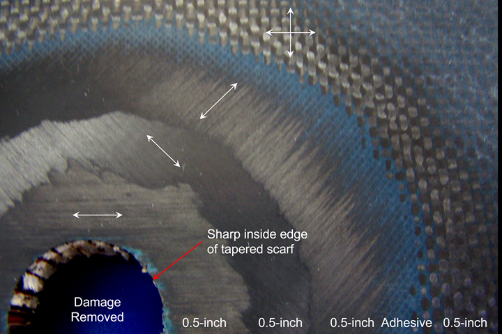
The scarf angle callout is typically expressed as a distance-to-thickness ratio (d:t) between 20:1 and 120:1, or simply by defining the equivalent “per-ply” distance (i.e., using a nominal ply thickness of 0.01-inch, at a 50:1 ratio, would give 0.01 x 50 = 0.5-inch per ply. For a four-ply laminate, the scarf distance would be 4 x 0.5 = 2.0 inches). Note that as the scarf distance increases, more of the original structure is removed, further weakening the parent structure. If the far side of the laminate is accessible, a double-sided scarf may be preferred (Fig. 2). Engineering repair analysis may be needed to determine the necessary scarf angle ratio for a specific application.
Fig. 2. A double-sided scarf repair can be used to minimize the amount removed from the original structure. Photo Credit: Abaris Training Resources
Scarf machining tips
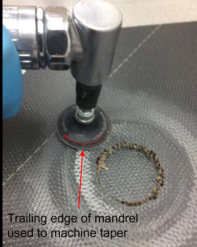
Fig. 3. The technician “feathers” the taper angle from the inside edge of the scarf outward to the desired dimension, using the trailing edge of the abrasive mandrel as the machining surface. Photo Credit: Abaris Training Resources
Machining with a handheld grinder can be tricky, whether it be a 90º die- grinder with a 2- or 3-inch abrasive mandrel, a jitterbug sander or a larger orbital sander that might be used for wind blade repair. Regardless, it takes a lot of practice for a technician to become competent in this skill. To be successful, the technician will need to learn to “feather” with the trailing edge of the grinder instead of using the leading edge like one might do for grinding metals. The objective is to have a uniformly smooth tapered surface without divots or gouges, proportionately following the part profile (flat or contoured surface profile) (Fig. 3).
The innermost edge of the taper should always come to a sharp point without any step remaining. Even a small step at this location can affect the performance of the scarf joint and should be mitigated by careful machining or, preferably, hand sanding to a fine point. A small amount of breakthrough at the edge is acceptable over a small step as shown in Figs. 1 and 3.
When repairing a sandwich structure, a core replacement procedure is required prior to making the patch. If this is the case, a slightly thicker core plug is bonded in place and machined flush to the desired profile, just prior to preparing the surface for bonding the repair patch as shown in Fig. 4. After sanding, the area is cleaned using a shop vacuum and approved dry wipes as needed.
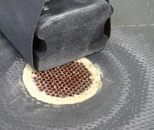
Fig. 4. The same density honeycomb core plug is bonded in place with core splice adhesive, cured and then machined or sanded to match the final profile. Photo Credit: Abaris Training Resources
The structural patch
The first step is to fabricate a template to lay out and cut the repair plies, extra ply and adhesive (if applicable) to the specified sizes and shapes, while matching the parent ply orientations. If the repair is circular, a common pair of dividers with an extra fine-point Sharpie pen can be used to lay out a set of concentric circles, marking the primary (or warp) fiber direction on the backing film or applied release film for each ply. If film adhesive is used, it should be cut to extend beyond the outermost ply by approximately 0.13-inch all around to provide for filleting.
Once the plies have been cut, re-energize the bonding surface of the parent laminate, plus an additional 0.5-inch all around the outermost ply with ultra-fine ScotchBrite abrasion, and clean off any remaining dust with approved dry wipes. (Alternately, treat the dry-wiped surface with blown ion plasma to further raise the surface-free energy, promoting wetting of the adhesive.)
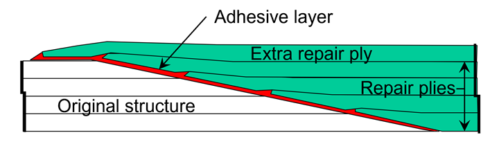
Fig. 5. Each repair ply is located directly over the adjacent ply in the structure, matching the fiber axial orientation. The extra ply (if required) is placed on top of the repair plies, overlapping the original surface, and oriented to match the outermost repair ply. Photo Credit: Greg Kress and Abaris Training Resources
Carefully lay out a set of targets and orientation information on the part (or on the adhesive layer) using an approved contrasting colored marker, so that each ply will be located properly. Apply the adhesive layer and the subsequent repair plies so that each repair ply overlaps the previous ply by the specified distance determined by the scarf angle ratio conversion (Fig. 5).
After the repair layup is complete, apply a peel ply layer, perforated film, fine glass bleeder layer(s), solid film, caul plate, thermocouples, heat blanket, breather layer and vacuum bag (if applicable) for processing. Cure the patch per the time/temperature recipe specified for curing the resin. An aluminum or composite caul plate provides for better compaction and a near-flush surface of the repair as illustrated in Fig. 6.
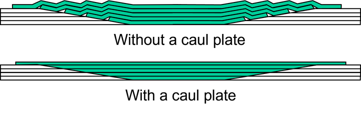
Fig. 6. A caul plate is used to achieve uniform compaction to the repair area, resulting in a highly compacted patch and a near-flush surface. Photo Credit: Greg Kress and Abaris Training Resources
After the patch is cured, the area can be prepared for painting as needed. Do not sand structural fibers during this process. An extra layer of fine glass fabric or adhesive could be added to the previous repair layup if this is an issue.
Myth busting
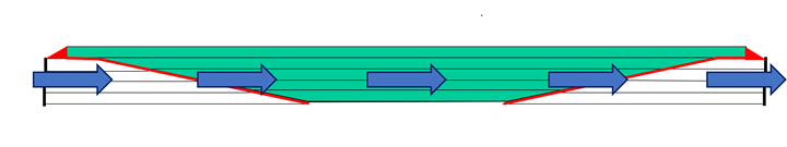
Fig. 7. Classical laminate plate theory states that a composite laminate is orthotropic (generally anisotropic), homogeneous material made up of multiple plies laminated together, not multiple plies all “flying in formation” on top of one another. Photo Credit: Greg Kress and Abaris Training Resources
For years, the industry has taught us that each individual ply in the repair patch transfers axial loads at the edges to the adjacent ply in the original structure. According to Greg Kress, senior engineering instructor for Abaris, “I do not support the concept of each ply in the original laminate transferring load across its individual overlap into each individual repair ply.” Instead, he says that once repaired, “the laminate acts as one homogeneous thickness to carry and transfer the load, not as individual layers transferring load” (Fig. 7). This makes sense to me, and it just proves that there is much more to learn in the world of composite repair.
Author’s note: Special thanks to Greg Kress for his contribution to this month’s column.


Related Content

Navy 3D Prints F/A-18 Composite Repairs to Cut Downtime by 50%
A joint Navy development program is using additive manufacturing to put composite repair capability directly in the hands of fleet sailors, with flight testing planned for summer 2026.
Read More
ROMAIN project validates robotic, prepreg patch repair for wind turbine blades
A developed prepreg-based patching system achieved an estimated 50% reduction in lamination and curing time compared to manual repair techniques, with field validation completed on operating turbines in Spain.
Read More
Toray obtains ABS type approval for in-situ VARTM ship repairs
American Bureau of Shipping (ABS) certifies use of jointly developed CFRP repair technique on FPSO and FSO industrial systems, addressing traditional steel restoration challenges.
Read More
Coltata Aerospace enhances Evans Composites' repair operations
Under Coltata’s platform, Evans has displayed significant improvement in operational performance, scalability and customer experience for aerospace and defense.
Read MoreRead Next

Easy-to-use kits enable infield repair of composite structures
Portable kit enables patch repairs using UV-cure glass fiber/vinyl ester or room-temp stored carbon fiber/epoxy prepregs and battery-powered curing equipment.
Read More
Moving toward portable, digitized composite part repair
Using digital twin technology, American GFM’s portable, automated inspection and scarfing system shows potential for on-site, data-driven composite aircraft part repair.
Read More
Avoiding the pitfalls of vacuum infusion processing
Understand the fundamentals of vacuum infusion processing (VIP), including pressure, permeability and race tracking, to prevent issues and produce consistent results.
Read More