


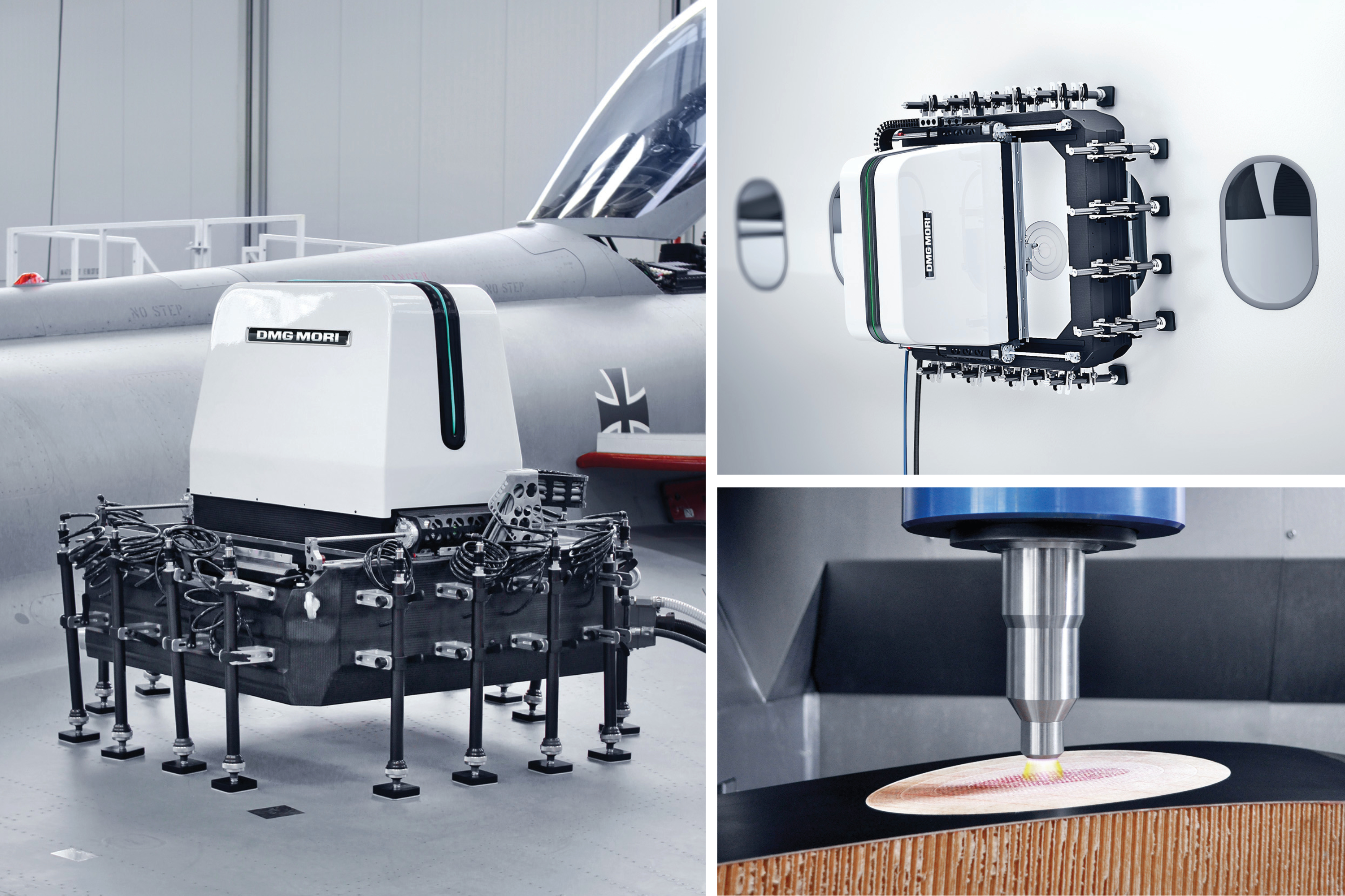
Automated, on-aircraft bonded patch prep. DMG MORI (Bielefeld, Germany) and SAUER (Stipshausen, Germany) have co-developed this ULTRASONIC mobileBLOCK 5-axis milling unit, which attaches to aircraft surfaces via 12 vacuum feet and provides multiple functions, including laser surface scanning, ultrasonic milling and plasma surface treatment. Photo Credit: DMG MORI/SAUER
Given the myriad subsystems for which aircraft maintenance, repair and overhaul (MRO) operations must offer service to air carriers — engines, wheels and brakes, avionics, landing gear, interiors and operations (e.g., auxiliary power, hydraulic power, electrical, environmental control, in-flight entertainment, waste and water systems) — the repair of composite aerostructures has been a relatively minor concern. However, the extent of composites use in aircraft has continued to grow. Indeed, as the Boeing 787 and, more recently, the Airbus A350 XWB, entered service, the use of composites extended far beyond flaps, ailerons and other control surfaces, engine nacelles, fairings and the vertical tail, to the entire forward wing structure and fuselage.
It’s important to note that, beyond the issue of weight savings, one of the main reasons cited for adopting composite airframes in these jetliners is that they drastically reduce corrosion- and fatigue-related maintenance tasks. Airbus claims a 60% reduction in these tasks for the A350 XWB, reducing the time required to perform maintenance checks and the total number of checks required over the plane’s life. It isn’t surprising, then, that composites from the 787 and A350 XWB don’t currently command a great deal of attention at MROs. Positive reports from the field note that the composite fuselages seem to be holding up very well to the normal abuse of daily commercial carrier service. But the planes are still very young. Experts say the real test will come in the next 5-10 years.


Airlines and MROs, accordingly, are gearing up to meet these coming composites maintenance demands. Air France Industries KLM Engineering & Maintenance (AFI KLM E&M, Paris, France, and Amstelveen, The Netherlands), for example, inaugurated a new composite aerostructures repair center at its Charles De Gaulle Airport base in summer 2015. The 20,000m2 facility — outfitted with autoclaves, nondestructive testing devices, surface treatment installations and sample testing laboratories — employs 200 technicians. Some of them are dedicated to R&D projects aimed at new solutions for next-generation aircraft. Listed with AFL KLM E&M among the world’s top 10 MRO providers, Guangzhou Aircraft Maintenance Engineering Co. (Gameco) also has its own new US$500 million composite repair center underway at its base in Guangzhou, China.
Working with aircraft that feature not only more composite structures, but larger, more integrated and increasingly complex composite structures, major airlines and MRO providers foresee several challenges. One is the need to perform an increasing number of repairs on the aircraft vs. in the repair shop. Another is to reduce the duration of repair processes without sacrifice of repair quality. A third is to increase the size limit for approved bonded repairs and to make progress toward the application of bonded repairs to more complex and primary structures.
Automating “on wing” repair
MROs, in fact, have performed composite repairs on the aircraft for decades, but typically only in special circumstances, for example, when the part is too large to be removed. However, this scenario is increasingly viewed as the future norm. AFI KLM E&M now performs composite repairs to the thrust reversers on the GE90 engine while both are still mounted on Boeing 777 aircraft because it has simplified logistics and shortened aircraft turnaround time (TAT). That is, it gets planes back in the air faster, earning money for air carriers.
The adhesive and prepreg layers used in bonded composite repairs — where a repair patch is adhesively bonded to replace the damaged material — can take 8-12 hours to cure. Further, the processes involved in nondestructively inspecting the damaged area, removing damaged material and preparing the area for adhesive bonding are typically lengthy. Therefore, technologies that will abbreviate repairs and critical TAT are in demand.
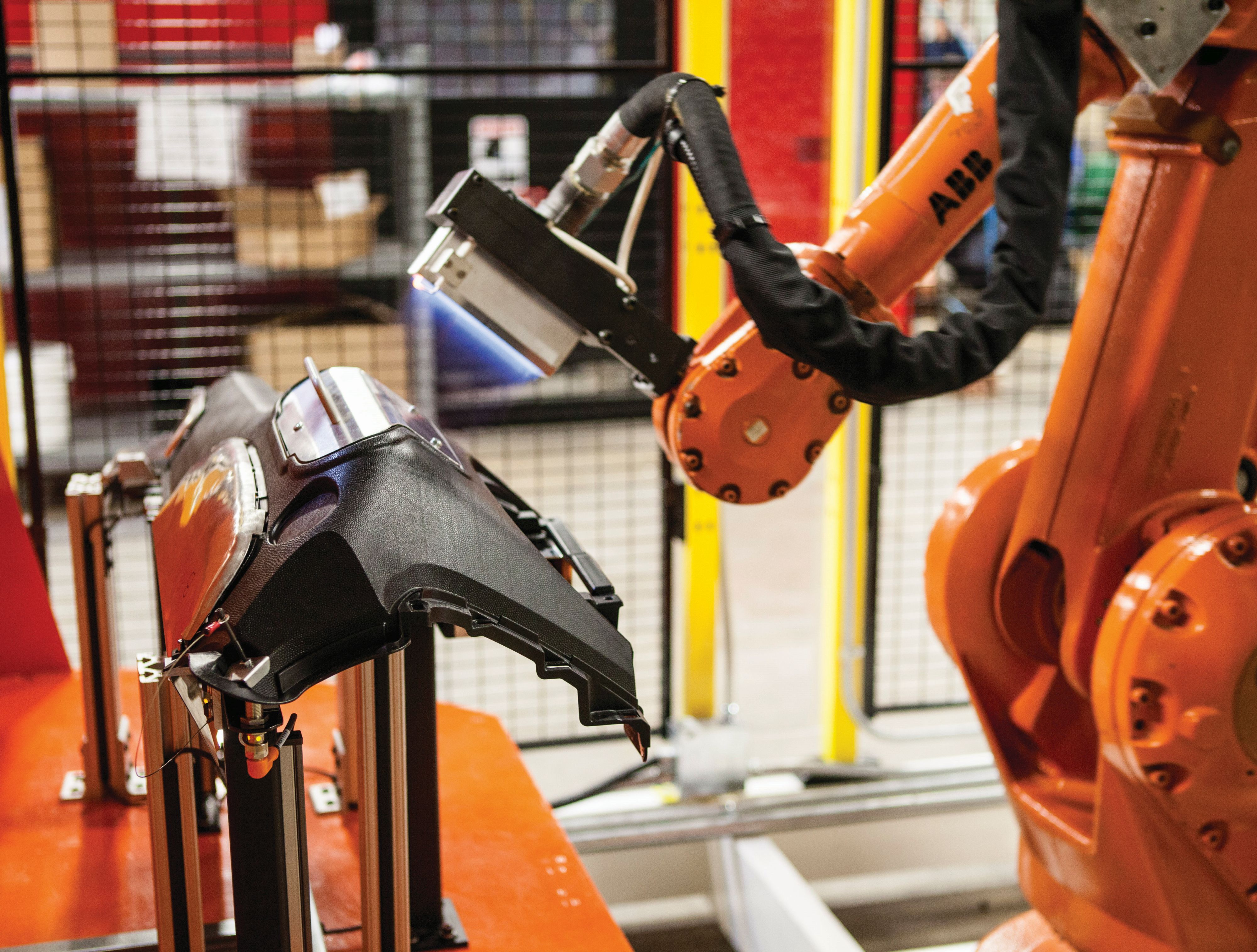
In 2011, CW reported on several automated repair processes in development (see “Primary structure repair: The quest for quality”). One, at Airbus Group Innovations (AGI, formerly EADS Innovation Works, Ottobrunn, Germany), uses a robotic arm with interchangeable heads to perform digital scanning, ultrasonic testing (UT), milling to remove damage, and automated tape laying to create a repair patch, and then automates patch application.
Building on the results of this Rapid Repair program, Lufthansa Technik (Hamburg, Germany) again partnered in 2012 with AGI, Airbus Defence & Space (formerly Cassidian, Manching, Germany) and Airbus Helicopter (Donauwörth, Germany) to complete the three-year follow-on project, Composite Adaptable Inspection and Repair (CAIRE).
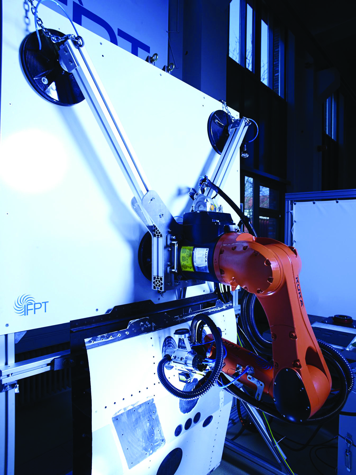
A prototype mobile robot has been built and tested on actual aircraft, demonstrating the ability to complete bonded composite repairs “on wing” for areas up to 1m2 on thick carbon fiber-reinforced plastic (CFRP) structure like that found in 787 and A350 XWB fuselages and wings. (CW’s 2011 article noted that most 787 carbon composite fuselage structures are typically ≈20 plies thick, but some range as high as 75 to 100 plies.) The mobile robotic unit is easily moved to the aircraft, hoisted using a forklift and mounted via suction cups — tasks that can be performed by one person, according to Lufthansa Technik innovation engineer Dr. Henrik Schmutzler. It then scans the damaged surface and digitizes it as 3D geometric data.
“Practically any type of scarfing geometry is then possible via robotic milling,” Schmutzler asserts. The software that generates the scarf was specifically developed during the project by partner iSAM AG (Mülheim an der Ruhr, Germany). “We looked at using the robotic arm to perform UT, but we saw no advantage.” For NDT, he says, technicians use an Olympus (Tokyo, Japan and Waltham, MA, US) RollerFORM ultrasound phased-array wheel probe, which moves quickly over part surfaces and yields very detailed results.
Another CAIRE project partner, Automation W+R (München, Germany), developed the robot’s three types of optical scanning systems. The first checks the scarfed surface before and after milling to measure any deviations from the specified digital design. The second determines the fiber orientation of each ply within the scarfed surface; these data are used to develop/confirm the repair and patch design. The third system analyzes surface roughness of the repair area prior to bonding the repair patch, which provides information about the expected bond strength of the area. “We have not yet defined an optimum surface roughness threshold,” Schmutzler admits, “but we have learned a lot about repair bond strength and the parameters that influence it.”
Previously envisioned automated tape laying is not part of the system, nor is the use of pre-cured repair patches. “The software does generate the shape and orientation of the repair plies needed and sends those to the automated ply cutter,” Schmutzler notes. Placement of these prepreg plies is still done by hand, as is application of the vacuum bag for cure, using a hot bonder.
A key to mechanical fastener-free repairs? Plasma systems like this flame surface treating system from Enercon Industries have proven their ability to improve adhesion and bond strength. Such systems also can be adapted for inline processing and the type of localized treatment that is necessary for bonded repairs. Photo Credit: Enercon Industries
Although surface treatment technologies are not currently included, participants in a follow-on project started this year (CAIRE ended in 2015) are looking at a variety of technologies to improve adhesive bond strength, as well as other improvements, and how to incorporate these efficiently into a composite repair process chain. (One type of surface treatment, plasma treatment, might prove to be a key enabler in the pursuit of certification- worthy, fastener-free adhesively bonded repair patches. See the photo above as well as “Aircraft composites repair: Plasma’s potential for better bonds").
Cutting repair time by 60%
Saving time/labor in complex repairs. Lufthansa Technik’s (Hamburg, Germany) mobile robotic repair system reportedly cuts repair time by 60% while enabling bonded patch repairs previously not possible or simply too time-consuming and expensive to attempt with conventional manual methods. Photo Credit: Lufthansa Technik
Lufthansa Technik claims the CAIRE robotic system improves scarfing efficiency by 60% vs. current manual processes. “The robotic milling is much faster than manual grinding of the tapered repair surface,” explains Schmutzler. “It also allows us to do more complicated repairs.” He explains that a circular scarf is easy to do manually because the scarf angle is the same around the area. In this case, he says, “the only concern is to make sure each ply has the same width. But if you’re limited in space or you have a load-adjusted repair, then you may need to do an elliptical scarf, which has varying scarf angles. So this gets very complicated and time-consuming to do manually.”
In a 1997 report on Advanced Technology Composite Fuselage Repair, Boeing explored bonded patch repairs with variable scarf angles — i.e., steeper scarf angles in the direction of lesser load and flatter angles in higher-load areas.
It found that the added complexity was too labor-intensive to justify the potential gains in structural efficiency.
Schmutzler contends the CAIRE automated system can reliably achieve any scarfing angle and smoothly transition between angles, with high-quality and practically no risk of damage to the underlying fibers or structure. “This may also enable reducing the size of the repair patch,” he says, “so you can make things possible which were not possible before.” For example, larger circular repairs may be replaced with smaller, variable-scarf-angled elliptical repairs.
Schmutzler says the goal for 2016 is to transition the previously prototype technology into service on flying aircraft. “We want to bring the system into our production at first for secondary structures, and then develop the knowledge and usage history to substantiate and develop it for more complex repairs.” He says the first in-service parts to be repaired will be from legacy aircraft (e.g., Boeing 737 and Airbus A320 nacelle parts) due to the large number of aircraft in service, which makes the system economical. He hopes that by the time the composite repair volume from the 787 and A350 XWB starts to ramp significantly, the automated system will be substantiated and ready to handle it.
The interest in developing robotic repair systems for composites is growing. DMG MORI (Bielefeld, Germany) and SAUER (Stipshausen, Germany) have unveiled the ULTRASONIC mobile BLOCK 5-axis milling unit (see photos below). The machine’s frame, x-axis gantry, servomotor housing, adjustment arms and z-axis slide are all made from CFRP, contributing to its light weight (90 kg), which facilitates its attachment to aircraft surfaces via 12 vacuum attachment points. The unit accommodates multiple functions, including laser surface scanning and ultrasonic milling, as well as surface cleaning and activation using atmospheric pressure plasma (Read more online about atmospheric pressure plasma treatment in “Plasma treatment as surface preparation for adhesive bonding” located under "Editor's Picks" on the top right). Boeing Aerostructures Australia (BAA, Melbourne, Victoria) also has developed what it terms a “scarf composite repair robot.” In its February 2015 Velocity newsletter, BAA reports that the robot has helped employees at Boeing Australia Component Repairs (Melbourne) achieve a 90% improvement in the time required to complete 737 thrust reverser inner wall repairs. The robot also has been used to repair test panels at Boeing’s Advanced Developmental Composite facility (Tukwila, WA, US).
Induction heating to speed repair
The German Aerospace Center (DLR, Stuttgart, Germany) also seeks to speed composite repair, but its approach focuses on minimizing the part’s exposure to heat (surface area and time) by means of laser- based surface preparation and a patch bonding technique that features an inductively heated caul plate.
“First, we remove the damaged material using a laser,” says project leader Markus Kaden. He explains this eliminates the cooling measures and the time required to clamp devices onto the part, typically required with milling, not to mention the cost of buying and reconditioning the milling tools.
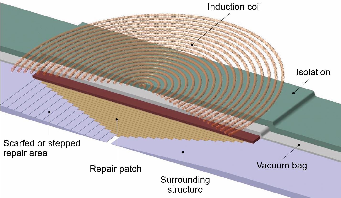
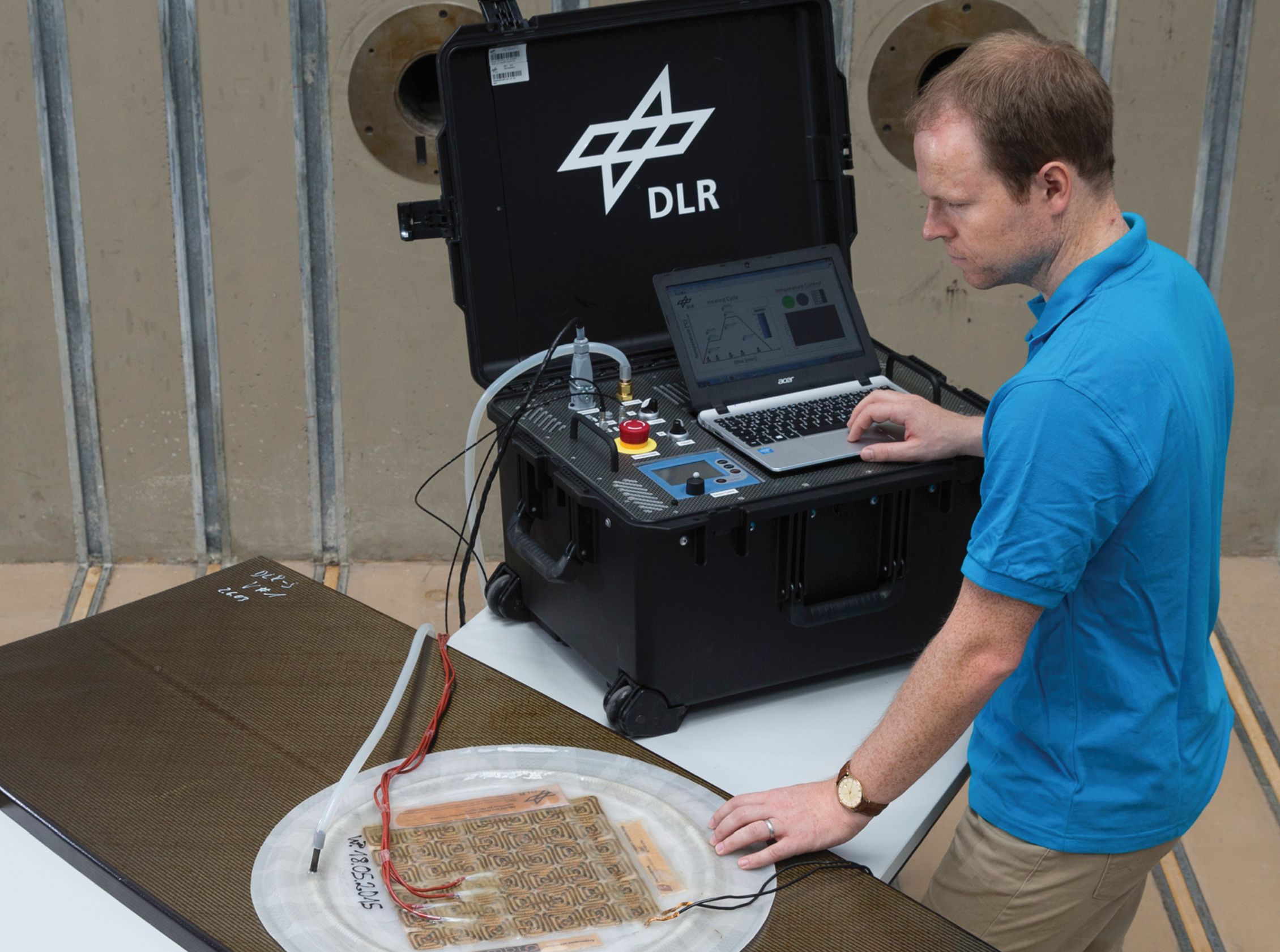
Fig. 1. Laser-enabled, inductively heated alternative. The German Aerospace Center’s (DLR, Stuttgart, Germany) new composite repair technology uses a laser to remove damaged material and an inductively heated metal caul on top of the repair patch to achieve fast and high-temperature cure. Photo Credit: DLR Institute of Structures and Design
Kaden continues: “Secondly, we use a metal sheet [caul plate] heated by induction, that is the same size as the patch and is pressed onto the patch by creating a vacuum.” He claims this caul plate (see Fig. 1) heats only the repair patch and damaged area underneath, while ovens or autoclaves heat the entire component.
The heating blankets, infrared lights and heated-air methods of more portable repair systems also confine heating to only part of the structure, notes Kaden. But he argues they still permit heat to extend beyond the specific area being repaired, which is undesirable due to the risk of inducing thermal stress damage to undamaged areas of the part.
After the caul plate is pressed onto the patch via vacuum bagging, the patch is bonded to the prepared repair area, while laptop software controls vacuum pressure and the temperature of the induction system, which can ramp heat at a rate of up to 65°C/ minute. This repair concept also may use an additional insulation layer on top of the inductively heated caul plate to reach temperatures above 300°C, enabling repair of high-temperature thermoset as well as thermoplastic composites. This concept has been developed into a mobile repair station that, in addition to the equipment for inductive heating of the caul plate, includes a vacuum pump to generate pressure on the patch, and laptop-based control capabilities for the individual processes in conjunction with flowmeters and resistance thermometer-type temperature sensors. Kaden says DLR plans to work with industry partners to develop this prototype-stage technology into a commercial product within the next 1-2 years.
Proof test for bonded repairs
It is important to point out that although these new technologies are aimed at eventually performing bonded composite repairs on the latest composite airframes, only bolted repairs are approved by regulators for structural (as opposed to cosmetic) repairs to primary composite aerostructures. This is because current nondestructive inspection (NDI) techniques cannot detect weak bonds between the repair patch and substrate. Therefore, bonded repairs are accepted on primary structure only in cases where the repaired structure will be able to withstand Limit Load (the highest load expected during the aircraft’s life) even if the repair patch fails completely. One obvious consequence of this requirement is a limitation on the size of the damaged area that can be repaired by bonding.
Airlines would prefer bonded repairs because bolted repairs are heavier and, in fact, can be detrimental to composite structures because they require that additional holes be drilled, which can reduce residual strength by as much as 50%. One solution, then, is to develop a reliable test to detect weak bonds directly after applying the bonded repair patch and throughout the life of the repair.
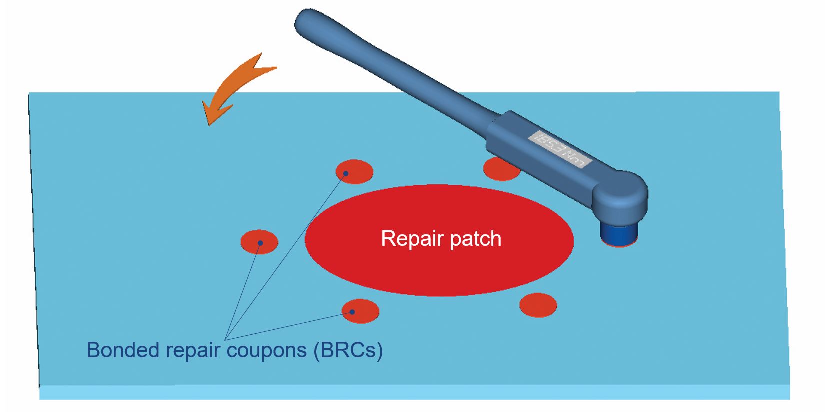
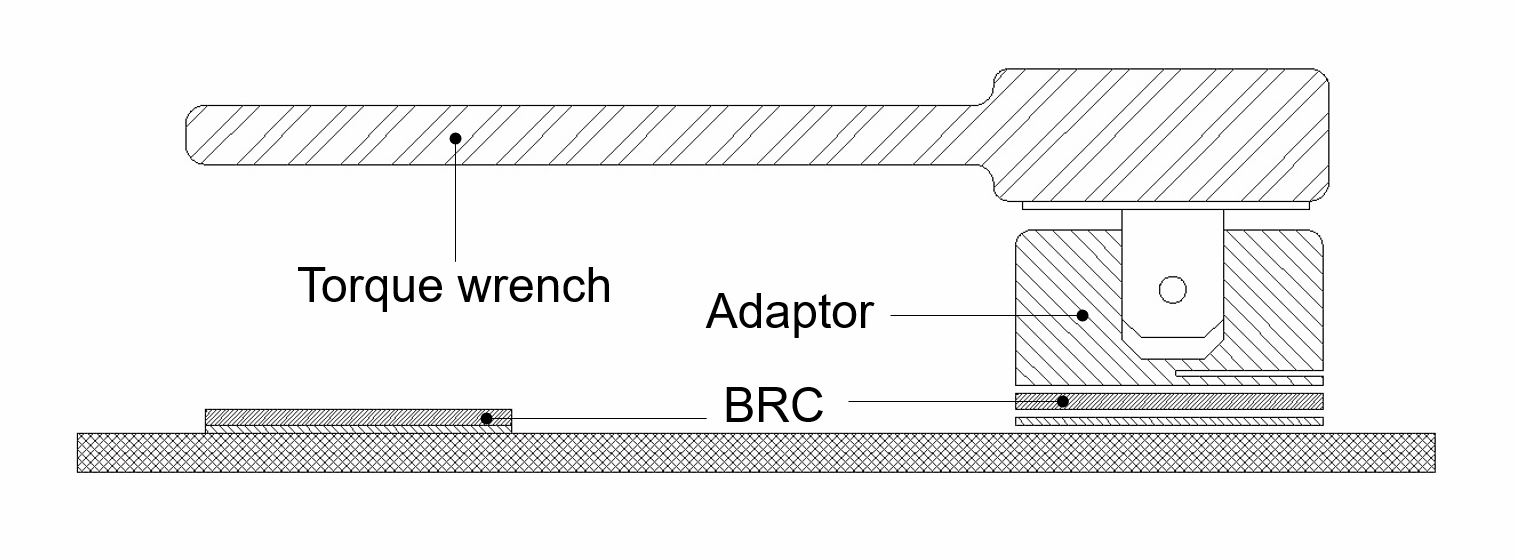
Fig. 2. Potential test method for bonded repairs? The Cooperative Research Centre for Advanced Composite’s (CRC-ACS, Victoria, Australia) BRC proof test comprises small, thin “satellite” bonded repair coupons (BRCs), situated around the circumference of the repair patch. These are subjected to shear loads applied through an adaptor using a torque wrench. Photo Credit: CRC-ACS
Direct loading of the patch is either infeasible or too expensive in many cases. There also is the risk of damaging the repair. The Cooperative Research Centre for Advanced Composite Structures (CRC-ACS, Victoria, Australia) and the Defence Science and Technology Group (DST Group, Melbourne, Australia), however, have developed a proof test that uses bonded repair coupons (BRCs) adhered to the parent structure at the same time as the repair patch (see Fig. 2).
BRCs are smaller versions of the repair patch, made of the same materials and applied under the same conditions, to be as nearly identical as possible. To conduct a proof test, a thin (typically less than 1-mm thick) BRC is subjected to a shear load, applied through a steel adaptor that is bonded to the BRC using an adhesive that is weaker than that used to bond the BRC to the parent material. The shear load is applied using a torque wrench. After each proof test, the adaptor, BRC and underlying adhesive are warmed to 80°C to remove them and restore the parent structure’s aerodynamic surface.
In an article published in the Journal of Adhesion & Adhesives, “Advances in the proof test for certification of bonded repairs – Increasing the Technology Readiness Level,” authors Alan Baker, Andrew J. Gunnion, John Wang and Paul Chang describe how the proof load was determined by conducting tests to failure on sets of BRCs applied under optimum bonding conditions in a controlled-environment laboratory. Carbon fiber/epoxy patches and laminates were fabricated using Hexcel IM7/977-3 carbon/epoxy prepreg tape and bonded using Cytec Solvay FM 73 and FM 300-2K epoxy adhesives, and Henkel Hysol EA9395 epoxy adhesive paste.
To validate the proof test’s ability to detect weak bonds, subsequent tests were conducted on specimens with under-cured adhesive, inadequate surface treatment prior to bonding, contamination of bonding surface and degradation due to service exposure and cyclic fatigue. The tests showed that poor surface treatments and under-cured adhesive can be readily detected by the BRC proof test. Surface treatments that give initially high strengths but degrade over time were not detected by the first proof test but should be detected by subsequent proof tests.
Tests also were conducted to see if the area around the repair and BRCs is damaged by repeated proof tests or BRC failures. Several BRCs were able to withstand more than 10 applications of the 95% proof torque without failure, increasing confidence in this approach as a potential means for in-service inspection. There were no instances of damage to the parent material.
Because they are thinner and, therefore, have less material to handle in-service loads and stresses, composite BRCs are considered a more “critical case” than (that is, more likely to fail before) the bulk repair. Finite element modeling of the BRC proof test and comparison with physical testing results confirmed that the BRC can closely represent the stresses experienced in the region at the edge of the repair patch, and, thus, can provide an indicator of fatigue damage in the patch and offers a good forewarning of degradation in the bonded repair. This inspection method has reached a technology readiness level (TRL) of 6. Following further refinements, resulting from feedback from a preliminary trial recently conducted with Royal Australian Air Force technicians, a full-scale on-aircraft trial is planned which should allow the technology to reach TRL 7. CRC-ACS and DST Group then hope that the BRC proof test can begin to earn acceptance as a standard test procedure for qualifying bonded composite repairs, on secondary structures, initially, and then on primary structures.
Continued progress
Repair of composite aerostructures continues to move forward. In 2011, CW reported progress toward the establishment of standards for training composite repair technicians, led by the Commercial Aircraft Composite Repair Committee (CACRC), which is overseen by SAE International (Warrendale, PA, US). The path envisioned then of technicians graduating from certified composite repair training programs, taking written and practical exams, and achieving a certification is slowly taking shape. CACRC has published a standard for composite repair training programs, which defines the knowledge required for an entry-level General Bonded Repair Technician. The group is now working on the next level, termed Commercial Bonded Aircraft Repair, to be aligned with the SAE-published standard AIR 4938, which outlines a general curriculum, comprising the minimum knowledge and skill requirements for a composite bond repair technician.
“Through the eQuaLified program, the industry is taking the output from the CACRC Training Task Group and developing a body of knowledge or BOK,” explains PRI’s executive VP and COO Joe Pinto. “This BOK takes international quality standards and industry best practices and puts them into one document. These documents are used by candidates who wish to take examinations. Training organizations can also access this information to develop training programs for bonded repair technicians.” The BOK reportedly contains all that the industry agrees a bonded repair technician should know. “Once we’ve established the BOK, our industry members will develop questions for both online and practical examinations.” The online, first-level exam is in development. The BOK is available at the PRI Web site.
Pinto notes that AIR 4938 and the General Bonded Repair Technician training standard were developed to be industry agnostic and, therefore, could be applied to the automotive/transportation, marine, wind power and other markets. He says the future goal is that PRI could audit composite repair training programs at OEMs and training organizations, as well as airlines and MROs, to ensure widespread compliance with the same standards, best practices and minimum requirements.
PRI oversees the Nadcap program, which already audits OEMs and some MROs, in which composites is considered as a special process area, as are NDT and electronics. Pinto says a few OEMs have mandated that all of their MROs must have Nadcap accreditation. This could be extended to composites repair.
“More still needs to be done,” says Lufthansa Technik’s Schmutzler in summary, noting that given the challenges noted above, it will take time before anyone sees the first bonded repair to a primary aerocomposite structure. Operators and MROs simply need more information about repair design. “But this will continue to open up step by step,” Schmutzler says, “as we gain experience with these new technologies.”


Related Content

Plant tour: Joby Aviation, Marina, Calif., U.S.
As the advanced air mobility market begins to take shape, market leader Joby Aviation works to industrialize composites manufacturing for its first-generation, composites-intensive, all-electric air taxi.
Read More
Sulapac introduces Sulapac Flow 1.7 to replace PLA, ABS and PP in FDM, FGF
Available as filament and granules for extrusion, new wood composite matches properties yet is compostable, eliminates microplastics and reduces carbon footprint.
Read More
Cryo-compressed hydrogen, the best solution for storage and refueling stations?
Cryomotive’s CRYOGAS solution claims the highest storage density, lowest refueling cost and widest operating range without H2 losses while using one-fifth the carbon fiber required in compressed gas tanks.
Read More
Materials & Processes: Composites fibers and resins
Compared to legacy materials like steel, aluminum, iron and titanium, composites are still coming of age, and only just now are being better understood by design and manufacturing engineers. However, composites’ physical properties — combined with unbeatable light weight — make them undeniably attractive.
Read MoreRead Next

Composites end markets: Energy (2024)
Composites are used widely in oil/gas, wind and other renewable energy applications. Despite market challenges, growth potential and innovation for composites continue.
Read More
From the CW Archives: The tale of the thermoplastic cryotank
In 2006, guest columnist Bob Hartunian related the story of his efforts two decades prior, while at McDonnell Douglas, to develop a thermoplastic composite crytank for hydrogen storage. He learned a lot of lessons.
Read More