
Composites extend service of oil and gas pipelines
Corrosion-resistant aramid fiber/thermoplastic liner gives new life to deteriorating steel subsea pipelines.
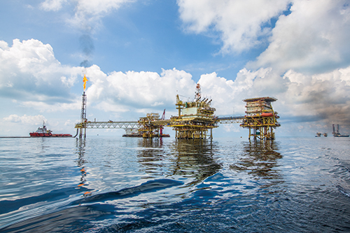
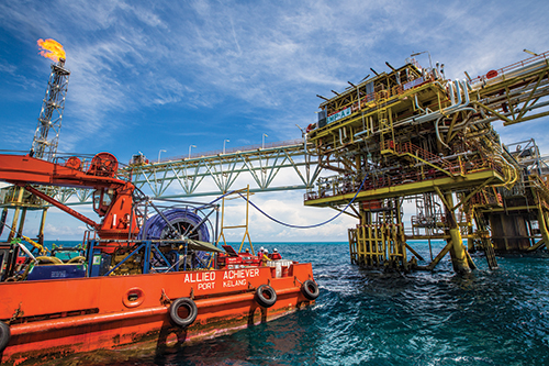
Rehabilitation for subsea pipelines: Anticorrosion Protective Systems’ (APS, Dubai, UAE) first InField Liner (IFL) was installed by APS during the summer of 2013 in a 203-mm (8-inch) diameter, 1.5-km-long crude oil pipeline between two offshore platforms in PETRONAS’ Samarang oil field in the South China Sea, located offshore from Sabah, East Malaysia. Source: APS
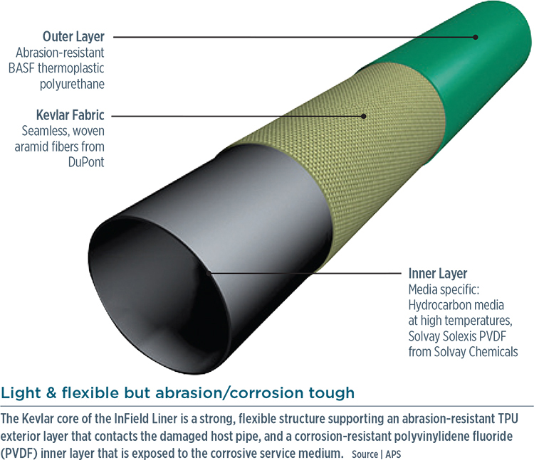
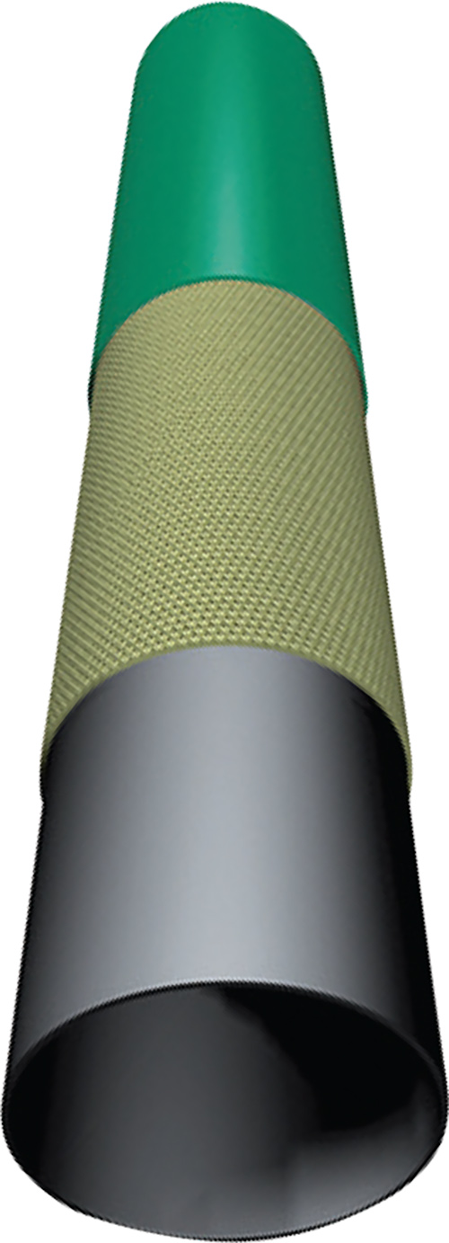
Light and flexible but abrasion/corrosion tough: The Kevlar core of the InField Liner is a strong, flexible structure supporting an abrasion-resistant TPU exterior layer that contacts the damaged host pipe, and a corrosion-resistant polyvinylidene fluoride (PVDF) inner layer that is exposed to the corrosive service medium. Source: APS
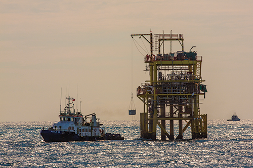
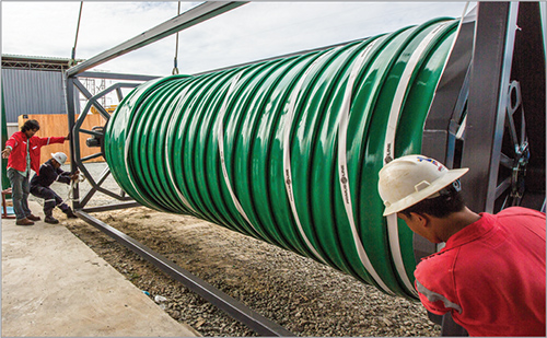
Ready to install on arrival: Here, an IFL, still wound on its transportation drum, is lifted aboard an offshore platform in the Samarang oil field, South China Sea. Source: APS
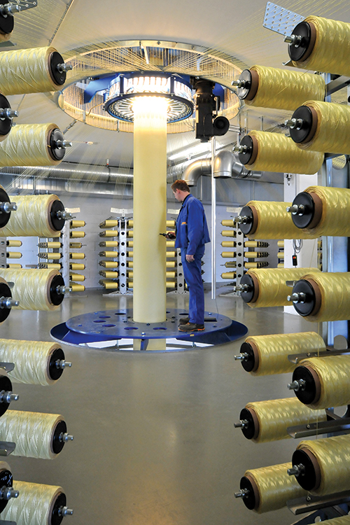
Step 1: A single-ply, 2-mm-thick cylindrical structure is woven from Kevlar. The aramid fiber is drawn from hundreds of spools and woven in a manner similar to sock knitting, in (as shown) vertical format. Source: APS
Step 2: Via a proprietary method, a layer of Solef PVDF (gray) is then extruded over the inner surface of the Kevlar cylinder, and a layer of thermoplastic polyurethane (green) is extruded over its outer surface as the aramid core moves continuously downward, held under tension to assure a smooth and consistent operation. Source: APS
Step 3: After the liner cools and the thermoplastic layers solidify against the core, the liner is reeled onto a transportation drum in a flat configuration. Source: APS
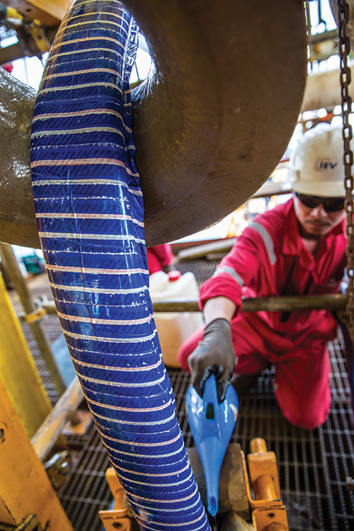
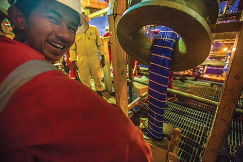
Step 4: The liner is folded and taped as it is reeled onto a dedicated installation drum, which is transported to the offshore site with other installation equipment and personnel. Source: APS
Step 5: After the host pipeline and the riser pipe are prepared, the liner is guided into the riser. Source: APS
Step 6: The liner is then pulled through the host pipe by a winching cable at about 10m/min. Source: APS
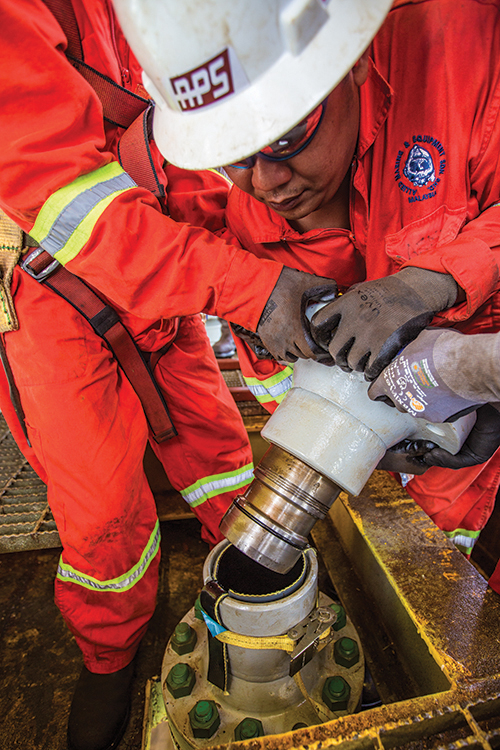
Step 7: When installation is complete, the liner is cut to length and air-inflated until it expands to form a tight fit against the host pipe. End-termination connectors are then installed, and the pipe is hydro-tested for 24 hours before the pipeline is recommissioned. Source: APS

The recent 101,000-gal oil spill off the California coast in the US offered grim testimony to the potential financial and environmental cost of corroded subsea pipelines. According to The New York Times, the cleanup of oil on beaches there had cost US$69 million, as of June 11, 2015, and costs were likely to climb. This and other articles about that incident pointed to pipe corrosion as the probable cause of the spill.
Global oil and gas interests operate more than 175,000 km of subsea carbon steel pipelines at varying depths around the world. These pipelines transport crude oil, gas and related products between offshore platforms and from offshore platforms to onshore facilities.


Counter-intuitively, one of the greatest threats to these undersea delivery systems is not saltwater, the external corrosive agent, but an unwelcome bacterial stowaway in crude oil that “breathes” the sulphates in crude and leaves behind highly corrosive hydrogen sulfide: “Due in large part to sulfate-reducing bacteria [SRB] accelerating internal corrosion, these pipelines can have a relatively short lifecycle,” says Robert Walters, global project director for Anticorrosion Protective Systems (APS, Dubai, UAE). Together with PETRONAS Carigali Sdn Bhd (Kuala Lumpur, Malaysia), APS has developed in response an innovative composite liner system that places a corrosion-resistant barrier between an aggressive service medium, such as SRB, and the steel. Known as the InField Liner, or IFL, the liner also offers a secondary containment capability in the event of a rupture or damage to the outer steel pipeline and promises to dramatically extend the service life of the pipes, which Walters says have historically needed replacement in as few as four years.
A team effort
Since 1978, APS has provided engineering, application and installation of specialized protective systems to the oil, gas, power and utility sectors in the Middle East and Asia through its Pipeline Rehabilitation and Specialized Coatings & Linings divisions. PETRONAS has expanded since its inception in 1974 as Malaysia’s custodian of its national oil and gas resources, to become a fully integrated international conglomerate listed on Fortune’s Global 500. Today, PETRONAS-related companies operate some 70% of the total 7,800 km of pipelines functioning in Malaysia.
For a number of years, protective composite liners for pipeline rehabilitation have been a growth technology onshore (see “Learn More,” p. 54), but no comparable offshore technology existed in 2009, when Walters met with PETRONAS executives to discuss solutions to SRB-related and other internal corrosion of that company’s subsea pipelines. Together, they determined the solution was a corrosion-resistant liner, and in April 2011, APS Pipeline Rehabilitation division went to work on a liner design concept.
Although APS designed and developed the liner system and is named as the joint inventor of the IFL technology, PETRONAS owns the IFL patent and trademark because it underwrote the development costs. APS is now negotiating with PETRONAS to secure an exclusive 20-year license to apply the intellectual property globally.
Critical design factors
The liner was designed to be pulled through pipe lengths of up to 5 km with multiple 90° bends having radii as small as 5D (D = nominal pipe outside diameter; 5D is a radius bend length that is five times the nominal pipe diameter). Each liner is custom designed and manufactured to match the original host pipeline bore, in nominal diameters from 152.5 mm to 457 mm (6 to 18 inches). To install the liner, then, it must be flexible enough to be folded and temporarily bound so it can be pulled through the pipe and around corners without damage or stoppage, and then subsequently inflated.
APS used Abaqus Unified FEA software (Dassault Systèmes, Waltham, MA, US) to develop and simulate a liner composition and manufacturing process that would meet the necessary mechanical strength properties — primarily the theoretical towing loads, liner folding and inflation forces, and the bending forces that would be incurred during installation, when the liner would be pulled through an existing pipe, particularly around tight bends.
APS envisioned the liner with a tightly woven, 100% aramid fiber cylindrical core. Kevlar — a product of DuPont Protection Technologies (Richmond, VA, US) — was selected as the liner’s structural aramid core largely due to its combination of high tensile strength and high degree of flexibility, which would allow it to be manufactured, folded and spooled in long lengths. Thermoplastic matrices were incorporated into the design as extruded layers, forming inner and outer barriers to chemical/corrosion resistance and giving the liner abrasion resistance during installation as it’s pulled through the bends of the pipe pathway.
Beyond the general design, each individual liner can be enhanced to meet environmental prerequisites, especially if it must withstand aggressive, hot, sour hydrocarbon service conditions of up to 110°C, or it can be planned and prepared for less aggressive service conditions, such as water re-injection or gas transmission.
Notably, a critical factor in each individual liner design is determining which end of the pipe to pull from. “The critical factors when pulling a liner tend to relate to the number and locations of the bends involved,” Walters explains. In a recent analysis undertaken by APS for a 3.5-km long pipeline that has six 5D bends, for example, different pulling force requirements were calculated for different directions of pull. That is, the pulling force requirement in one direction was calculated as 12 tons, but in the opposite direction it was calculated as requiring nearly 72 tons. This difference was primarily due to the location of the 5D bends on the pipeline. Walters interprets the findings: “This analysis shows that it is not just a static tensile value of a liner that is important, but makes it clear that all the host pipe specifications and parameters combine to add into and impact onto the final calculation process. In the case of this particular pipeline, if the liner were to be pulled in the 12-ton loading direction, the liner then still retained a safety factor of well over 100% in relation to its overall tensile strength.”
Design and manufacture have followed testing and qualification procedures in accordance with the American Petroleum Institute (API, Washington, DC, US) Recommended Practice API RP 15S (First Edition, March 2006) Qualification of Spoolable Reinforced Plastic Line Pipe, as well as API series 17 Subsea Production System, and applicable ASTM (W. Conshohocken, PA, US) and NACE (Houston, TX, US) standards. All liner-testing qualifications have been subjected not only to full verification by independent laboratories but also to third-party inspection, Walters says.
Synchronized vertical production
APS InField Liners are produced in a multi-stage patented and proprietary process that is executed throughout vertically rather than in the horizontal orientation typical of pultrusion, continuous filament winding and other linear composites fabrication processes (see Steps 1 & 2, at left), with all process phases carefully synchronized. “The complete IFL is produced in a single process, with only the length being the defining factor as to when production should be started and stopped,” Walters says. The entire APS production system is computer-controlled to produce the stipulated weaving pattern, tube diameter and length to meet specific liner design requirements. The control system is a proprietary software package specifically designed for this function.
“Every element of the fully automated manufacturing procedure is carefully and continuously monitored and controlled with real-time computer assessment and feedback so as to ensure absolute operational precision,” Walters emphasizes. “Every facet of the liner production quality assurance is recorded, and the produced liner quality is, thereafter, further verified by extensive testing prior to factory acceptance and certification.”
Production begins with the liner’s aramid core cylinder (Step 1). The Kevlar aramid is woven in the tubular shape without a mandrel, in a manner similar to knitting a sock, says Walters. Instead of the circular needles often used for knitting socks, the patented weaving system uses an automated circular wheel.
To produce an IFL for a recent nominal 152.5 mm (6-inch) outside diameter pipe, the system pulled from a battery of more than 250 spools of dry Kevlar aramid cords to weave a high-strength, single-ply, 2.0-mm-thick cylindrical structure. DuPont defines a Kevlar cord as a single string of Kevlar, which is composed of a number of threads, which, in turn, comprise a number of filaments.
While the finished core cylinder moved downward as it was woven, the highly corrosion-resistant inner and outer thermoplastic layers were extruded onto it (Step 2). The inner barrier layer — the initial line of internal corrosion defense — was first extruded onto the inside surface of the Kevlar core. For this layer, which is directly exposed to the corrosive service medium, APS chose Solef PVDF, a polyvinylidene fluoride resin from Solvay Specialty Polymers (Alpharetta, GA, US). This semi-crystalline fluoropolymer provides stability in harsh thermal and chemical environments and has an established record of high-performance service in offshore hydrocarbon applications.
The IFL’s outer layer, which contacts the inner surface of the host pipe, was then extruded onto the exterior of the core. The outer layer is an abrasion-resistant thermoplastic polyurethane (TPU) from BASF Polyurethanes (Waterloo, Germany).
After inner and outer extrusion layers were applied, the liner was allowed to cool under controlled conditions until the extruded thermoplastic layers crystallized and solidified against the core. When the crystallization phase was complete, no secondary manufacturing operations were necessary. During the entire process, the vertical cylinder of core and its interior/exterior thermoplastic layers continued to move downward, held under tension to assure a smooth and consistent operation as the liner was continuously produced and then cooled. In this way, the liner “actually removes itself from the weaving system and related internal and external extrusion processes,” Walters explains. The cooled crystalized liner was then automatically reeled directly onto a transportation drum in a flat configuration and prepared for shipment to the customer’s location (Step 3). Shipping reels are specifically designed to accommodate up to 5 km of liner and can be packed into standard 20-ft- or 40-ft-long shipping containers.
Successful, cost-effective installations
The first installations, in 2013 and 2014, went into internally corroded pipelines that had been marked for imminent closure. The inaugural IFL, in the summer of 2013, was installed by APS in a 203-mm (8-inch) diameter, 1.5-km-long crude oil pipeline operating at 10 bar, between two offshore platforms in PETRONAS’s Samarang oil field in the South China Sea, located offshore from Sabah, East Malaysia. The liner was shipped to the project yard in Labuan, where it was put through a folding-and-banding process: The flat liner was pulled from the shipping reel and passed through a series of machines that fold it lengthwise into a U-shape, then use flexible PVC film-based tape to hold the liner’s folded shape in position. This process reduced the liner’s diameter and, thus, reduced the pulling forces required to pull it through the host pipe.
The folded/taped liner was then reeled onto a dedicated installation drum (Step 4). The drum and other installation equipment and personnel were transported to the offshore site and a guidance framework was set up to define the liner pulling path. The host pipeline was cleared of its flow media and thoroughly cleaned, measured and assessed for its exact condition. Next, the riser pipe — the vertical pipeline that connects the platform-based processing equipment above the water line to the horizontal pipeline network and related equipment on the seabed — was modified to accommodate installation of the liner end connector units after liner installation.
A winching cable was pulled into position in two steps: First, a specially designed pig was blown from the main winching platform to the liner installation drum platform. (A pig is a device commonly used for cleaning and maintenance of pipelines; it can be blown through a pipe by raising the air pressure behind it, which pushes the pig forward). The pig carried a small, lightweight cable through the pipeline. A secondary winch on the installation platform was then attached to the small cable, which, in turn, wss used to pull a larger, main winching cable through to the installation drum for connection to the liner towing head.
When the existing pipeline was thoroughly cleared and cleaned, the winching cable was in position and other liner installation preparations were complete, the liner was positioned (Step 5) and pulled through the host pipe (Step 6). Pulling force was closely monitored and controlled during the installation process. This pulling operation is normally performed at an approximate pulling speed of about 10 m/min, Walters notes. A liner can be pulled through a 1.5 km pipe in about 2.5 hours.
After it was in place, the liner was cut to length, and then inflated, using low air pressure (Step 7). As it inflated, the banding tapes broke and the liner expanded to fit tightly against the host pipe’s inside surface. End-termination connectors were then installed and the pipe was hydro-tested for 24 hours at a pressure set at approximately 1.5 times the normal pipeline operating pressure, or ~15 bar (1.5 times the 10-bar pipeline pressure). When the hydro test was deemed successful, the pipeline system was recommissioned for service.
Another IFL installation, in a 152.5-mm (6-inch) diameter, high-pressure (60 bar) gas pipeline, took place at the same time and in the same location. And in 2014, following the success of the first IFL installations, APS installed its liners in four additional PETRONAS Cargali 152.5-mm gas pipelines, totaling some 4 km in length, in the West Lutong field, about 50 km offshore and north of the city of Miri, in Sarawak, Malaysia.
The result? Walter says, “PETRONAS now estimates the service life of these lines to have been extended by at least 30 years.” Further, PETRONAS Carigali says IFL has saved the company as much as 50% of the capital costs of a replacement pipeline.
Commercial solution for offshore pipe
Walters says that IFL is market-ready and APS is able to service all the major oil companies that have expressed interest in the IFL subsea pipeline rehabilitation system. Since the successful Samarang installations, Walters has approached major offshore oil and gas operators in Southeast Asia, the Middle East, North America and West Africa.
“The response to the enormous potential of this subsea technology has been overwhelming,” he says, emphasizing, “For the first time in the history of offshore pipeline operations, there is now a viable alternative to pipeline replacement. And not only a technology advance, but an alternative, whereby major anticipated cost savings — compared to new pipe laydown — is the main driving factor.”
Rehabilitation and repair by lining rather than replacing deteriorating pipelines on land using cured-in-place pipe (CIPP) has proven to be a remarkable time- and cost-saving idea that has captured about half of the sewer line rehabilitation in the US — including sewer lines in onshore oil fields and petrochemical manufacturing plants — and also has been formulated for drinking water. Further, it is on a growth curve in Europe, for gas and pressurized water distribution, foul outflow and sewage line systems (see “Cured-in-place pipe: Trenchless trends,” under "Editor's Picks" at top right).
Since its inception, CIPP in a variety of forms has created a substantial market for composite materials in the rehabilitation and repair rather than replacement of underground pipelines. Although IFL by APS is a distant cousin to CIPP, technologically, it is the first commercial composite liner for pipeline operators in the offshore market. IFL looks like an idea with equally great potential to create a similar rehab/repair market for undersea pipelines.


Related Content

Cycling forward with bike frame materials and processes
Fine-tuning of conventional materials and processes characterizes today’s CFRP bicycle frame manufacturing, whether in the large factories of Asia or at reshored facilities in North America and Europe. Thermoplastic resins and automated processes are on the horizon, though likely years away from high-volume production levels.
Read More
Carbon fiber in pressure vessels for hydrogen
The emerging H2 economy drives tank development for aircraft, ships and gas transport.
Read More
Materials & Processes: Resin matrices for composites
The matrix binds the fiber reinforcement, gives the composite component its shape and determines its surface quality. A composite matrix may be a polymer, ceramic, metal or carbon. Here’s a guide to selection.
Read More
The potential for thermoplastic composite nacelles
Collins Aerospace draws on global team, decades of experience to demonstrate large, curved AFP and welded structures for the next generation of aircraft.
Read MoreRead Next

Cured in place pipe: Trenchless trends
A variety of CIPP products are enabling the rehabilitation, rather than excavation and replacement, of underground pipe for wastewater and drinking water.
Read More
Cured in place pipe: Trenchless trends
A variety of CIPP products are enabling the rehabilitation, rather than excavation and replacement, of underground pipe for wastewater and drinking water.
Read More
Cured in place pipe: Trenchless trends
A variety of CIPP products are enabling the rehabilitation, rather than excavation and replacement, of underground pipe for wastewater and drinking water.
Read More