Advancing thermoplastic composites and RTM for Clean Sky 2 in Spain
EURECAT leads projects for TPC keel beam, window frames and thermoset RTM fuselage frames with TPC shear ties for next-gen aircraft.

From bottom left, counter-clockwise: Welded thermoplastic composite stiffened panel made by CETMA, mold design for a thermoplastic composite window frame made by EURECAT, RTM C-frame demonstrator made by EURECAT and compression-molded thermoplastic shear tie made by DEMA. SOURCE | EURECAT, CETMA, DEMA.
The EURECAT Centro Tecnológico de Catalunya (EURECAT Technology Centre Catalonia, Barcelona, Spain) is a private, nonprofit R&D organization with 11 facilities, 650 employees and 50 million euros in annual revenues. “It is the second largest R&D center in Spain,” explains Angel Lagraña Hernandez, program director for the aeronautics and space market at EURECAT. He explains that part of EURECAT’s revenue is from the Catalan government and of the remainder, half must come from private companies — mostly small-to-medium enterprises (SMEs) — while the other half may be public, such as the European Union-funded Clean Sky 2 program. “We now have 18 Clean Sky projects,” notes Lagraña, “which we were awarded purely on the basis of competitive submissions in response to calls for proposals.”
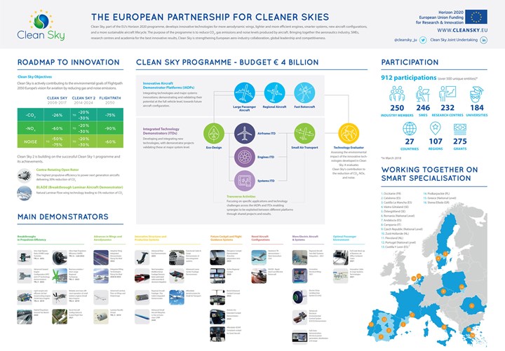
SOURCE | Clean Sky 2
Examples of how composites feature in Clean Sky 2’s numerous goals and planned technology demonstrators include:
- The next generation Multifunctional Fuselage Demonstrator — leveraging thermoplastics for cleaner skies
- Circular Economy: Composite Fuselage for regional aircraft takes shape
- Leveraging motor racing expertise for Clean Sky’s FastCan
“EURECAT is highly transverse, working in automotive, rail and other industries in addition to its work in aerospace,” says Lagraña. “It also has a lot of activities in IT such as data analytics and blockchain, etc. Composites 4.0 is one of its strategic areas.” Within composites, he notes that EURECAT primarily works in out of autoclave (OOA) technologies. “We focus on thermoplastics and liquid compression molding, including process monitoring in real time, including monitoring the resin’s glass transition temperature (Tg) during processing.” (Keep reading to the section on COFRARE, at the end of this blog, to see more about this Tg monitoring.)
EURECAT’s most recent composites-related projects in Clean Sky 2 include:
- KEELBEMAN to demonstrate a thermoplastic composite keel beam (This project has received funding from the Clean Sky 2 Joint Undertaking under the European Union’s Horizon research and innovation programme under GAP n° 785435 KEELBEMAN);
- WINFRAME 4.0 to build thermoplastic composite (TPC) window frames for the Green Regional Aircraft (GRA) demonstrator in Clean Sky (2008-2017) and extended to the Regional Aircraft IADP (Innovative Aircraft Demonstrator Platform) in Clean Sky 2 (2014-2024);
(This project has received funding from the Clean Sky 2 Joint Undertaking under the European Union’s Horizon research and innovation programme under GAP n° 821323 WINFRAME 4.0.) - COFRARE 2020 for thermoset fuselage frames made using resin transfer molding (RTM) with TPC shear ties.
(This project has received funding from the Clean Sky 2 Joint Undertaking under the European Union’s Horizon research and innovation programme under GAP n° 821261 COFRARE 2020.)
Thermoplastic composite keel beam
Clean Sky 2 - JTI-CS2-2017-CFP06-LPA-02-20. Project duration: March 2018 to December 2019
The objective of the KEELBEMAN project is to develop a manufacturing-oriented keel beam structure for an A320 type aircraft that enables high aircraft production rates but at an affordable cost via thermoplastic composites. In addition to EURECAT as project coordinator, partners include:
- Airbus (Toulouse, France) as topic manager
- CETMA (European Research Centre for Technologies Design and Materials, Brindisi, Italy)
- The CT Engineering Group (CT Ingenieros, Madrid, Spain), a firm with numerous global offices which has a multi-year contract with Airbus for aircraft development such as research on the fuselage, wings and rear end via its Hamburg, Germany office; research on the rear end (Spain); research on fuselage and power plant related structures (Toulouse, France) and wing development (Bristol, U.K.)
- Sofitec (Sevilla, Spain), a specialist in aerostructures manufacturing and assembly with expertise and production capacity in composites.
The CT Engineering Group provided full modeling of the keel beam geometry via its Toulouse office, while Sofitec developed nondestructive testing (NDT) inspection. “This is very challenging with such a closed box structure,” Lagraña points out.
Development of keel beam structures
“Today, most aircraft keel beams are made in metal except for the Airbus
A350, which is monolithic carbon fiber composite,” says Lagraña. “This requires large numbers of rivets and a significant amount of time for assembly.” He explains that the keel beam is a critical structure in the fuselage, “There have been cases where the keel beam has broken during landing, causing the whole fuselage to crack and break.
According to a 2011 article by Steve Wilhelm, the A350 keel beam is 70% composite, 54 feet (16.5 meters) long, put together with 10,000 fasteners, weighs 1.2 tons and forms the backbone of the aircraft. Wilhelm notes that the competitive Boeing 787 aircraft “doesn’t depend on such a robust keel structure, because more of the hull strength comes from composite barrels that are fastened together end-to-end.” The article then quotes Michel Merluzeau, managing partner of G2 Solutions LLC aerospace consultancy (Kirkland, Wash., U.S.), who describes the Airbus design as “more conventional” and “less risky” but points out the keel beam is “essential to the structural integrity of that aircraft.”
Airbus actually pioneered a composite keel beam for the A340 in 2001. But as described above, the high number of rivets required works against the weight savings possible by using composites. Thus, a key target in the KEELBEMAN project is to minimize fasteners by using thermoplastic composite components which are welded together.

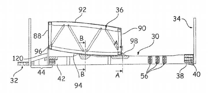
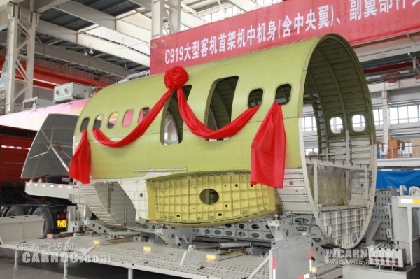
Airbus pioneered a composite keel beam for the A340 in 2001. The A350 keel beam is 70% composite. SOURCE | (left) Commercial Aircraft Composite Technology by Ulf Paul Breuer and (right) Airbus, 2011, photo by P. Bassen/Visuelles, flightstory.net
TPC keel beam
“The development of a thermoplastic composite keel beam using welding for assembly is part of Airbus’ development of the aircraft of tomorrow, which includes programs such as the Wing of Tomorrow and Fuselage of Tomorrow,” says Lagraña. “Within KEELBEMAN, we have produced a 250-millimeter by 500-millimeter by 1-meter-long demonstration section of a keel beam with stringers and demonstrated the feasibility of welding this structure with as much automation as possible.”
Lagraña notes the demonstrator wall plates and stringers were made using carbon fiber/polyetherketoneketone (PEKK) unidirectional (UD) tape in a continuous compression molding (CCM) process developed by CETMA (see “Aerospace-grade compression molding” and “PEEK vs. PEKK vs. PAEK and continuous compression molding”). “There are also ribs for transverse stiffeners which were made using traditional non-isothermal compression molding by EURECAT,” adds Lagraña.
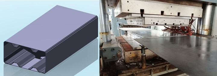
CAD view (no fasteners) of the KEELBEMAN demonstrator and walls being made via CCM. SOURCE for all images | EURECAT and CETMA.
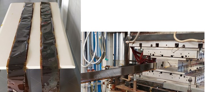
L-stringer preforms are molded using continuous compression molding (CCM).
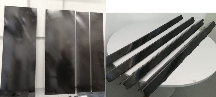
Finished walls and L-stringers for KEELBEMAN demonstrator.
Ribs for the KEELBEMAN demonstrator were made using non-isothermal compression molding. Shown here, CETMA developed these thermoplastic composites processes in the first Clean Sky program’s ECO FAIRS project to produce helicopter parts. SOURCE | “Eco-design and manufacturing of thermoplastic structural fairing for helicopters” by Silvio Pappadà, CETMA.
Induction welding as key enabler
Lagraña notes that CETMA played a key role not only in the parts production for KEELBEMAN, but also in the assembly of the demonstrator using its patented induction welding machine and technology. This welding was originally developed in the first Clean Sky program’s ECO FAIRS project (2011-2014), along with the isothermal and non-isothermal compression molding of TPC structures shown above. In ECO FAIRS, CETMA used all of these technologies to produce a prototype demonstrator based on the existing upper panel (stringer-stiffened skin panel) of an Agusta Westland helicopter tail as well as a curved sponson fairing demonstrator. Though these were made using CETEX (provided by TenCate, now Toray Advanced Composites) T300 3K 5HS carbon fiber textile with double-sided PPS (polyphenylene sulfide) film, CETMA also proved out induction welding with PEEK and PEI composites.
SOURCE | “Eco-design and manufacturing of thermoplastic structural fairing for helicopters” by Silvio Pappadà, CETMA.
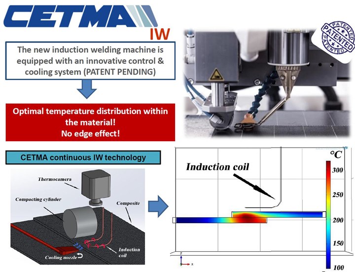
CETMA selected induction welding (IW) as the most promising of the thermoplastic composite welding techniques and worked with welding and electronics engineering specialist SINERGO srl (Valdobbiadene, Treviso, Italy) to develop a new induction welding machine. The gantry-based SICE 1 WIDE machine offered by SINERGO (see image below) is capable of continuous welding of aerospace-quality parts up to 1 meter by 1 meter. It includes a robust control system to ensure optimized temperature distributions are achieved within the materials being welded. The machine is equipped with a cooled cylinder to apply consolidation pressure and with an air-cooling system to remove heat where required, such as in the edges, where the flow of the induced electrical eddy currents is constrained, resulting in high current density and overheating. It is also possible to install the CETMA induction welding head onto a 6-axis robotic arm for welding geometrically complex shapes.
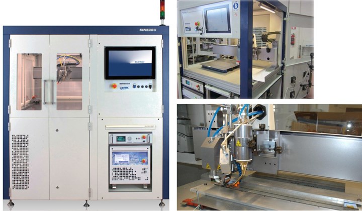
CETMA developed and patented induction welding technology seen here in the gantry-based SICE 1 WIDE system offered by SINERGO. SOURCE | CETMA and SINERGO
CETMA has also developed the ability to optimize its induction welding process by using simulation tools, performing numerical analysis using COMSOL Multiphysics (COMSOL Inc., Burlington, Mass, U.S.) finite element modelling (FEM) software. It verified these models through a large number of physical tests. CETMA confirmed its optimized process parameters by single-lap tests on welded coupons, in which shear strength values were very close to the maximum reported in literature. Notably, these were also much higher than the maximum values when using structural adhesives, says CETMA.

Induction welding simulation, including temperature distribution for the welding interface using a double-D induction welding coil. SOURCE | CETMA competences presentation.
CETMA has proven its welding capability for a wide variety of materials, including woven and UD carbon fiber, as well as PEEK, PEI, PEKK, PP, PA6, PA12 and even welding to CF/epoxy using a thermoplastic PVB (polyvinyl butyral) hybrid layer for transition from the thermoset substrate to the thermoplastic face for welding. (Much of this section’s details were draw from CETMA competences presentation and the CORDIS final report for ECO FAIRS.) CETMA applied for a European patent in 2014 and inventors Silvio Pappada and Andrea Salomi were awarded with patent EP2801472A1 in 2016. CETMA has published numerous papers and presentations on this technology, including:
- “Finite element simulations to support the development of out-of-autoclave technologies”, A&D, 11-12 Oct 2012
- “Finite Element Simulations to Support Continuous Induction Welding of PPS-Carbon Composites”, SEICO 13, 11-13 March 2013 “Paris”
- “Development of a New Induction Welding Machine for Thermoplastic Composites in the Aerospace Sector”, Italian Association of Aeronautics and Astronautics XXII Conference Napoli, 9-12 September 2013
- “Induction welding in aerospace sector”, TPRC, Thermoplastic Composites European Consortium, Web-meeting, December 2013.
- “Full scale tests on thermoplastic components for aerospace sector”, SEICO 14, 10-11 March 2014 “Paris”
- “New induction welding equipment for the aerospace sector”, JEC magazine, No. 87, March 2014, pp. 89-91.
KEELBEMAN status and path forward
Airbus visited CETMA in December to see the final welding of the 1-meter demonstrator section, and the KEELBEMAN team also held a final review of technology readiness level (TRL). “We are getting good results and are maturing the technology from TRL 3 to TRL 4,” says Lagraña. Next steps could include further development to TRL 6 and production of a full-scale keel beam to be installed in one of the Clean Sky 2’s demonstrators, such as the WP 2.3.2 full-size lower center fuselage, but this has not yet been decided.
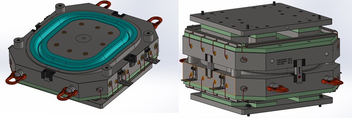
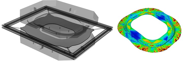
EURECAT’s mold design for producing thermoplastic composite window frames (top), a spring holding system to minimize wrinkles (bottom left) and 3D forming simulation using AniForm showing thickness distribution (bottom right). SOURCE | EURECAT
WINFRAME 4.0 project for TPC window frames
Another thermoplastic composite (TPC) program for EURECAT is WINFRAME 4.0, with the goal to develop and manufacture 24 window frames for a regional aircraft fuselage/cabin integrated ground demonstrator (see explanation of Clean Sky 2’s developments for Regional Aircraft and the Full-scale Innovative Fuselage and Passenger Cabin Demonstrator below). WINFRAME 4.0 partners include:
- Multinational aerospace company Leonardo (Rome, Italy) as topic manager
- EURECAT
- Sofitec.
“The method we are using can produce one window frame every 10 minutes,” says Lagraña. Production steps include: heat TPC laminate blanks in an oven, translate to a mold, close the mold in a press, apply heat and pressure for 10-20 minutes and demold the finished part(s). “This approach not only achieves shorter cycles than liquid molding but also much less expensive tooling,” he adds. “The process is well known in the automotive industry, it is compression molding in a highly automated configuration which increases the quality of the part, but the aerospace materials used are different, in this case a carbon fiber-reinforced PPS and carbon fiber from Toray Advanced Composites (formerly TenCate). By the end of this project, we will have achieved a TRL 6 for these technologies,” says Lagraña.
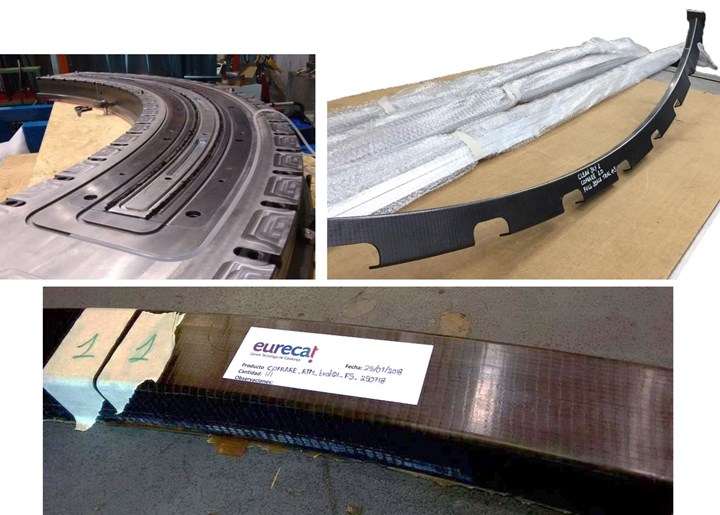
In the Clean Sky 2 COFRARE 2020 project, EURECAT is helping to produce C-frames for a composite fuselage using RTM (left) and to attach those frames, thermoplastic composite shear ties compression molded by DEMA (right). SOURCE | EURECAT and DEMA.
COFRARE project: RTM C-frames and thermoplastic shear ties
The COFRARE 2020 project is an extension of the initial COFRARE 2.0 project:
Clean Sky 2 - JTI-CS2-2015-CFP02-AIR-02-16. “Process development for composite frames manufacturing with high production rate and low cost”Project duration: 2016 to 2018.
The goal of the Clean Sky 2 COFRARE 2.0 project was to develop a competitive and feasible manufacturing process for carbon fiber composite frames to be used in a composite panel-based fuselage for regional aircraft. Partners included:
- Naples-based Tier 1 aerospace supplier and engineering/industrialization firm DEMA (Design Manufacturing SpA, Somma Vesuviana, Italy)
- EURECAT
- LGAI Technological Center S.A., a division of Applus+ Laboratories in Barcelona, Spain provided testing.
The goal of the next generation COFRARE 2020 project is to manufacture full-scale composite frames and shear ties to be used in the Clean Sky 2 fuselage/cabin integrated ground demonstrator. This demonstrator is organized within Clean Sky 2’s Regional Aircraft IADP (Innovative Aircraft Demonstrator Platform) and detailed in Section 5.2.2 of the March 2015 Joint Technical Programme document:
“Regional aircraft are a key element of Clean Sky through a dedicated ITD (Integrated Technology Demonstrator) - Green Regional Aircraft (GRA), providing essential building blocks towards an air transport system that respects the environment, ensures safe and seamless mobility, and builds industrial leadership in Europe. In Clean Sky 2, … The demonstration objectives of the Regional Aircraft IADP are much more complex, comprehensive and challenging than those of the current Clean Sky GRA project, which was forced to work within budget and time constraints. …”
The 2015 Joint Technical Programme outlines Regional Aircraft development to include two flying test-beds and five large integrated ground demonstrators. The latter includes the Full-scale Innovative Fuselage and Passenger Cabin Demonstrator: “The fuselage will be a full-scale demonstration of technologies for composite material, structures and manufacturing aimed to [achieve] weight and cost reduction and to minimize the environmental impact through eco-design and energy consumption optimization all along the life-cycle (towards a zero-impact).”
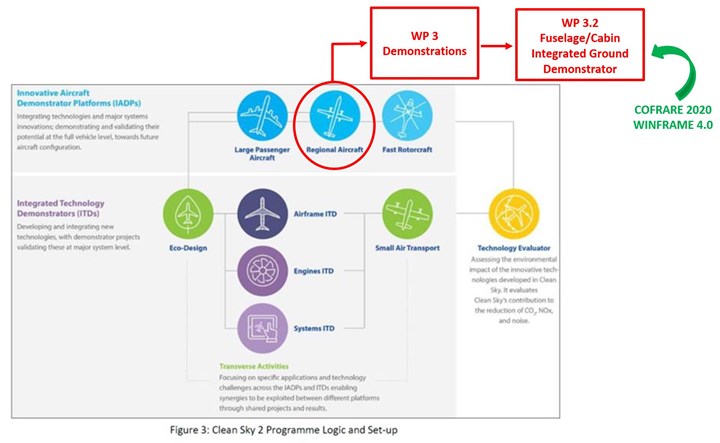
How COFRARE 2020 (and WINFRAME 4.0) fit into the Clean Sky 2 organization for large demonstrators. SOURCE | Leonardo.
COFRARE 2020 project partners include:
- Leonardo as topic manager
- EURECAT
- DEMA
- Aircraft components and assemblies manufacture A. Abete (Nola/Marigliano, Italy).
“In COFRARE 2020, we are making fuselage frames using RTM (resin transfer molding), which will be integrated into the fuselage demonstrator,” explains Lagraña. “We are using the Ziplus technology from Shikibo (Osaka, Japan) which produces preforms that are well-suited for injection with resin.” Shikibo Ltd. is part of Composite Alliance Corp. (Dallas, Texas, U.S.), and offers a variety of textile preforming technologies.
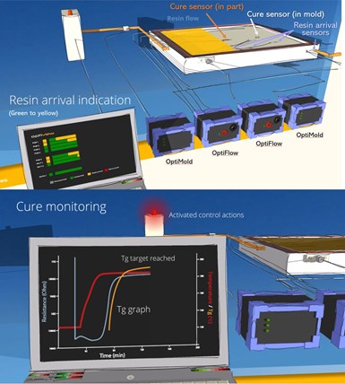
One interesting aspect of this program is the use of sensors from Synthesites (Uccle, Belgium) for real-time monitoring of resin arrival, temperature, pressure, Tg and cure. “The sensors are located in specific areas of the composite part and the RTM tool to optimize the resin injection strategy,” notes Lagraña. Injection is achieved using a highly automated system supplied by ISOJET (Corba, France), which is also part of Composite Alliance Corp. Synthesites sensors are dielectric sensors, but unlike most dielectric analysis (DEA), which is based on alternating current (AC), Synthesites uses direct current (DC). “Our sensors perform well with high resistivity materials like resins and because we are applying a single voltage, we don’t have to analyze multiple frequencies, yet we achieve a high accuracy, even at the end of cure,” explains Synthesites director Dr. Nikos Pantelelis.

Synthesites cure sensors (left to right): HP-RTM, In-mold Carbon, Vacuum bag and Inline sensor. SOURCE | Synthesites.
Synthesites uses DC dielectric sensors, its OptiFlow and OptiMold systems, and OptiView and ORS software to monitor resin arrival, temperature and resistivity, and then calculate viscosity, gel time, Tg and cure, alarming for when target Tg and state of cure is reached. These systems can also be used to provide intelligent control of equipment and processes. SOURCE | Synthesites.
“We met Synthesites at a SAMPE conference in 2011,” Lagraña recalls. “Theyspoke about sensors to shorten cure cycle. We are exploring how to automate preforms for the fuselage frames and even using faster processing with HP-RTM (high-pressure RTM), but still you are at 3-4 hours process time. However, with Synthesites, we have cut cure cycle by 50 percent by monitoring Tg. We are now testing for properties. These sensors can work at high pressure but in our RTM processing, we are using only 8 bar of pressure.”
The Synthesites DC dielectric sensors, OptiFlow liquid resin flow monitoring system and OptiMold cure monitoring system have been demonstrated in production by various wind blade manufacturers. They are also used by Bombardier Aerospace (Belfast, U.K.) to produce the liquid composite molded wing for the C-Series now Airbus 220. The German Aerospace Center (DLR, Stade, Germany) has demonstrated cure cycle reduction up to 50% with both autoclave prepreg and RTM, while the National Composites Center (NCC, Bristol, U.K.) has demonstrated that even for highly reactive resins, the real-time Tg calculations made from sensor measurements of resin temperature and resistivity are as accurate as Tg measured from cured panels using differential scanning calorimetry (DSC).
Joining frames with TPC shear ties
Another key part of COFRARE 2020 is a more high-volume production method to produce the hundreds of shear ties and brackets that are required to join the RTM fuselage C-frames to the composite fuselage panels. “We are developing 255 different geometries for thermoplastic composite brackets produced by compression molding,” says Lagraña. (Note, GKN Fokker has multiple Clean Sky 2 projects where it will produce TPC brackets for the Multifunctional Fuselage Demonstrator in the Large Passenger Aircraft IADP; this work in COFRARE 2020 is for smaller, regional aircraft.) The basic method is shown below, using matched steel tools and a heated press. “The cost of such compression molding tools is only 2,000 euros, which is very affordable compared to RTM tooling,” he adds. “Stamping also achieves very short cycle times.”
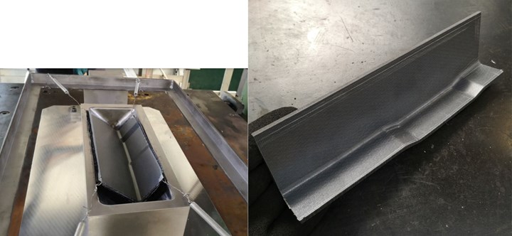
Shear ties for the C-frames in the COFRARE 2020 project are made using compression molded thermoplastic composites to reduce tooling cost and part cycle time. SOURCE | DEMA.
EURECAT is invested in remaining at the forefront of composites technology development, says Lagraña. “We believe that the pressure for a clean environment will dramatically increase the use of composites in all transportation, and that affordability and performance will go together. This is why we focus on automated, out-of-autoclave technologies to offer to our customers.”
Stay tuned for my upcoming blog on the Clean Sky 2 STUNNING and MECATESTERS projects, which will discuss the development of welded TPC brackets for the Multifunctional Fuselage Demonstrator and a full characterization of PAEK for this project. I will also blog on Synthesites in more detail as well as more of CETMA’s developments in composites. 2020 is going to be a very interesting year for composites!
Related Content
Forvia brand Faurecia exhibits XL CGH2 tank, cryogenic LH2 storage solution for heavy-duty trucks
Part of its full hydrogen solutions portfolio at IAA Transportation 2022, Faurecia also highlighted sustainable thermoplastic tanks and smart tanks for better safety via structural integrity monitoring.
Read MoreJEC World 2022, Part 1: Highlights in sustainable, digital, industrialized composites
JEC World 2022 offered numerous new developments in composites materials, processes and applications, according to CW senior editor, Ginger Gardiner, most targeting improved sustainability for wider applications.
Read MoreMoving toward next-generation wind blade recycling
Suppliers, fabricators and OEMs across the composite wind blade supply chain ramp up existing technologies, develop better reclamation methods and design more recyclable wind blades.
Read MoreMaterials & Processes: Fibers for composites
The structural properties of composite materials are derived primarily from the fiber reinforcement. Fiber types, their manufacture, their uses and the end-market applications in which they find most use are described.
Read MoreRead Next
Composites end markets: Energy (2024)
Composites are used widely in oil/gas, wind and other renewable energy applications. Despite market challenges, growth potential and innovation for composites continue.
Read MoreFrom the CW Archives: The tale of the thermoplastic cryotank
In 2006, guest columnist Bob Hartunian related the story of his efforts two decades prior, while at McDonnell Douglas, to develop a thermoplastic composite crytank for hydrogen storage. He learned a lot of lessons.
Read MoreCW’s 2024 Top Shops survey offers new approach to benchmarking
Respondents that complete the survey by April 30, 2024, have the chance to be recognized as an honoree.
Read More







.jpg;maxWidth=300;quality=90)


