
IVW research to better determines fiber friction coefficient
Highly variable system development contributes to the increasing precision and efficiency in the manufacture of filament-wound composite components.


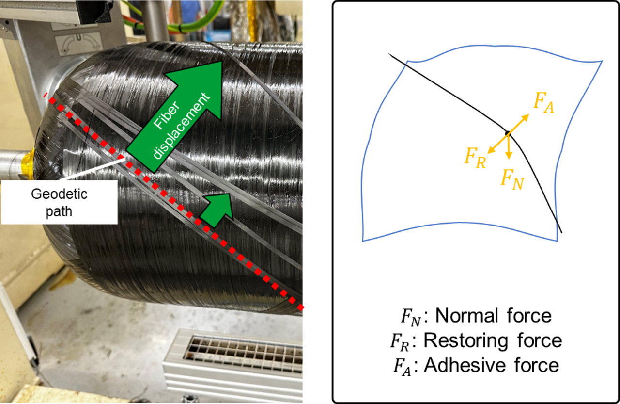
Figure 1: Fiber displacement due to insufficient adhesion force (left) and simplified force equilibrium on winding surface (right). Photo Credit, all images: IVW
Leibniz-Institut für Verbundwerkstoffe (IVW, Kaiserslautern, Germany) has been active in the research field of fiber composites for more than 30 years, from concept to finished part. In some of its more recent work with filament winding technology, IVW has developed a system for determining the coefficient of friction transverse to the longitudinal direction of the fibers in order to perform and obtain repeatable and automated measurement results for determining the fibers’ coefficients of friction. The system circumvents some of the major disadvantages of current measurement methods IVW reports.
Filament winding is an established process that is widely used to manufacture rotationally symmetrical fiber composite components such as pipes, pressure vessels and shafts. It has also been proven to be an efficient method for producing complex structures. Due to the often highly curved surfaces that need to be wound with fiber material, fiber adhesion on the surface is essential — too little fiber adhesion can lead to rovings displacement, which are then no longer on the predetermined path, but in an undefined area of the component, without contributing to the overall strength of that component. Among other things, precise knowledge of the friction coefficient between the roving and the surface is therefore crucial for its planning and control, irrespective of the specific winding process. In the worst case, an incorrect estimation of the frictional properties can significantly change the quality of the wound component. In addition, unwanted slippage of the fibers on the component can lead to disruptions in the process flow.


According to IVW, fiber displacement on curved surfaces always occurs when the geodesic path is left and the adhesion force of the roving is not sufficient to hold the fiber in position. The geodesic path describes the shortest connection between two points on a surface. Uniaxial stress state prevails here, which means that forces only occur along the longitudinal axis of the fiber. Outside of the geodesic path, restoring forces act on the fiber, which favor slippage. A simplified sketch of the equilibrium of forces acting on the roving as well as the effects of insufficient adhesion force is shown in Fig. 1.
The exact determination of the coefficient of friction between fiber and surface is crucial for the entire winding process. However, it is a complex task influenced by many factors (surface condition, temperature, fiber type, etc.). Therefore, various methods have been developed to determine it.
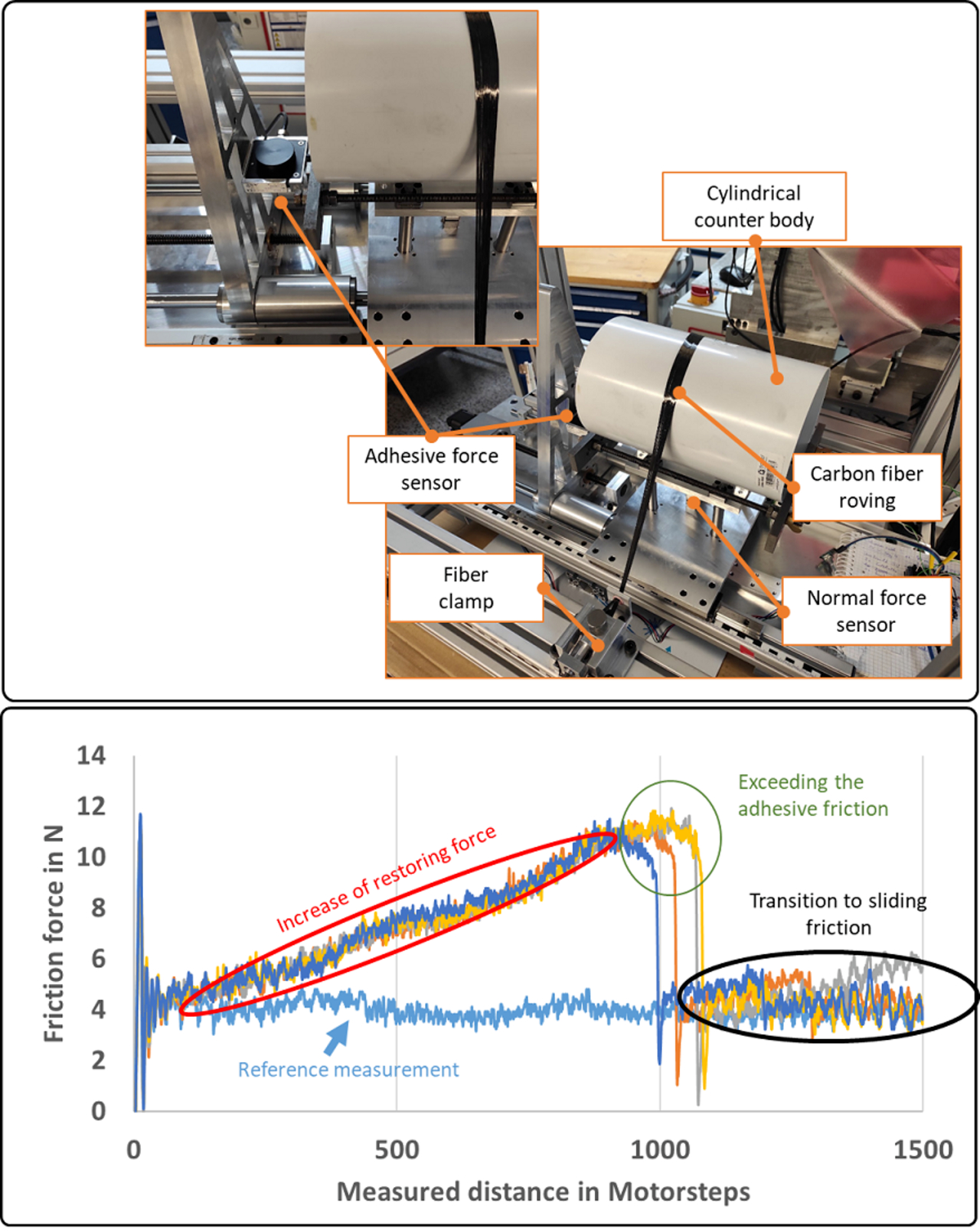
Figure 2: Test setup ready for testing with fiber clamped (top) result of a series of four tests, including reference measurement (bottom).
A common determination technique is the capstan method, in which a bundle of fibers is placed over a roller and loaded with a weight. The resulting forces enables conclusions to be drawn concerning the friction properties. However, due to the specific design of the measurement system, the coefficient of friction can only be determined along the fiber. As a result, the measurement findings can only be transferred to the prevailing stress state during the winding process to a limited extent.
Another common method uses specially shaped winding mandrels to visually record the slippage behavior of the fibers. While the determined behavior is very close to that of the real production process, the visual evaluation only offers limited possibilities for automating the measurement process. In practice, other methods are used to determine the coefficient of friction, but they all have different limitations and disadvantages.
IVW says its highly variable system setup makes it possible to circumvent some of these challenges for repeatable, automated measurement of the coefficient of friction. Material parameters such as the fiber type, and process parameters such as the surface property for deposition, can be varied and adapted to the desired conditions (fiber-fiber contact, different takeoff angles, temperature, aging, etc.). The system thus offers extensive potential for investigating the coefficient of friction and its influencing factors.
Fig. 2 shows the setup of the test rig in a test-ready state with clamped fiber and a characteristic measurement result for a friction value measurement of a carbon fiber towpreg. During the buildup of the fiber adhesion force, a force increase can clearly be seen in the course of measurement. After exceeding the adhesion force, a sharp drop in the measured force follows. This then changes to a sliding friction curve.
The results of the tests can be used to determine the influence of temperature, aging, surface properties, etc. on the adhesion force of the roving on a defined surface. Transferring the results to the practical winding process supports further optimization with regards to the overall process and component performance. As a result, the load path-compliant design of struts, tubes or pressure vessels such as hydrogen storage tanks, can be precisely adapted to the specific adhesive properties of the fiber material. Slippage of the fibers and the associated reduction in component performance is thus avoided. In addition, precise knowledge of the coefficient of friction means that transfer paths within wound components, which are unnecessary for component strength, can be reduced to the absolute minimum. This saves both fiber material and weight.


Related Content

Post Cure: Parallel winding technique demonstrates CFRP anisogrid design optimization
Over the years, CIRA has demonstrated its patented CFRP parallel winding technique in a variety of ways for space applications. The lattice structure for the Vega-C launcher stage is a prime example.
Read More
CFRP planing head: 50% less mass, 1.5 times faster rotation
Novel, modular design minimizes weight for high-precision cutting tools with faster production speeds.
Read More
Optimizing robotic winding of composite tanks and pipes
Pioneer in mandrel-based reinforced rubber and composite products, TANIQ offers TaniqWindPro software and robotic winding expertise for composite pressure vessels and more.
Read More
ASCEND program completion: Transforming the U.K.'s high-rate composites manufacturing capability
GKN Aerospace, McLaren Automotive and U.K. partners chart the final chapter of the 4-year, £39.6 million ASCEND program, which accomplished significant progress in high-rate production, Industry 4.0 and sustainable composites manufacturing.
Read MoreRead Next

TPRC research studies void removal mechanisms in VBO processing
New publication evaluates vacuum bag only-consolidated carbon fiber/PEEK tapes to determine the role of different void removal mechanisms in thermoplastic composites.
Read More
Troubleshooting thermoforming of thermoplastic composites
Challenges with the thermoforming/stamping process and potential solutions addressing the associated parameters and complex material behaviors.
Read More
Thermoplastic composite materials and processing interactions
Selection of product material formats and their interactions with various process methods heavily influence a final TPC part’s properties and fabrication options.
Read More