
Real-time assessment of thermoset composites curing
The combination of material state management (MSM) software and an encapsulated sample rheometer (ESR) enables real-time cure recipe management or cure model development inside the autoclave.


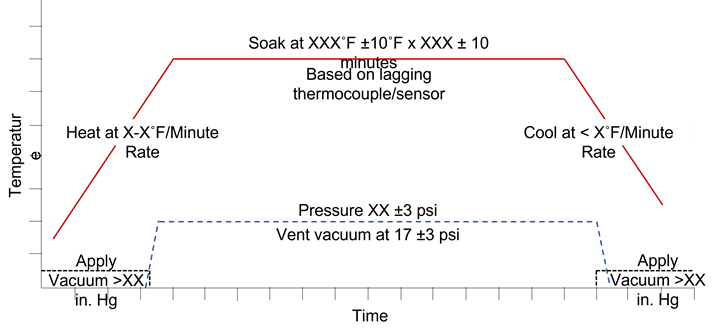
Figure 1. The cure recipe graph is used to communicate the heat rate, soak temperature and duration, the cooling rate, vacuum and pressure requirements and all permissible process boundaries as written in the process specification for each material. Photo Credit: Abaris Training Resources
When curing thermoset composite materials in a press, oven or autoclave, we commonly use a simple cure cycle recipe that designates temperature over time, as well as other process requirements such as vacuum and/or pressure.
These recipes are often depicted in a graph that shows the thermal ramp rate(s) and one or more isothermal holds, as well as temperature and time boundaries and vacuum and pressure conditions. A generic example is shown in Figure 1.


What happens if there is a thermal excursion from the cure cycle recipe? How do you prove that part is cured? Or what if there are no excursions, but the post-process thermal analysis of specimens taken from the part laminate show a lower-than-required thermal glass transition temperature (Tg) or residual chemical reaction (heat flow out of the specimen) after cure?
If thermal properties are not met, the laminate is not fully cured and would likely be dispositioned by a material review board (MRB) or quality assurance (QA) group to determine if a post-cure is viable or if the part is to be scrapped — an obviously expensive and undesirable outcome. This then brings up another question: How can we ensure that we obtain a proper cure?
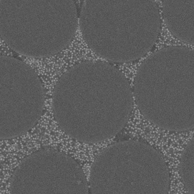
Figure 2. This microphoto shows just how much area the NS occupies between the filaments and how much the resin volume is reduced as a result. This may be one reason that the reaction time is delayed when heated. Photo Credit: 3M
A while back, I had an experience with (at the time) a new-to-market, low-temperature curing, nanosilica (NS)-fortified tooling prepreg (Fig. 2). After being subjected to the manufacturer’s recommended initial cure temperature of 60°C (140°F) for 8 hours, the resulting glass fabric-reinforced tool laminate later deformed during a manufacturer’s prescribed free-standing, post-cure cycle. After verifying that all thermocouples had measured temperature at the tool laminate to pattern interface, and that the8-hour time had been met, we decided that additional testing was necessary to find out why the resin was still immature after processing, and how much time at the initial isothermal temperature is really required to enable a stable post-cure.
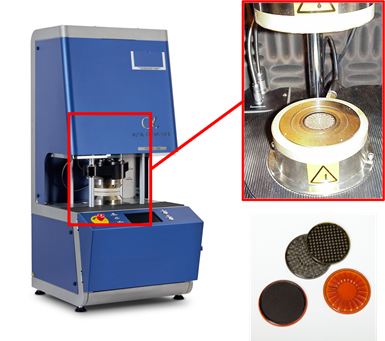
Figure 3. Encapsulated sample rheometer (left) die set for samples (upper right) and coupons (lower
right). Photo Credit: Alpha Technologies and AvPro
A test plan was developed and implemented to conduct dynamic mechanical analysis (DMA) using a high-torque, encapsulated sample rheometer1 (ESR) driven by process simulation software embedded in a computer process control suite2 capable of real-time material state management (MSM) (Fig. 3).
The software sent time and temperature signals to the ESR and recorded the viscoelastic data in real time from each of a series of five glass and five carbon fiber prepreg samples that were tested at five different isothermal temperatures. This data was graphed and analyzed to determine the actual time needed to process the prepreg at each temperature as shown in Figure 4. We also had the ability to determine the Tg of each coupon after each run using the same equipment and software to determine the maximum starting temperature for the post-cure cycle that follows the initial cure.
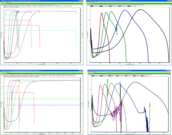
Figure 4. Graphs showing overlaid data from thermal analysis of glass (top) and carbon fiber (bottom) coupons. The graphs on the left show the elastic storage moduli (Gp) for each coupon and the graphs on the right depict the dissipative loss moduli (Gpp) for each coupon. The Gp correlates to the stiffness and the peak Gpp is indicative of vitrification of each coupon at each specified isothermal temperature. Photo Credit: AvPro and Abaris Training Resources
It turned out that not only did the glass fiber fabric3 prepreg samples require additional time to cure, but the carbon fiber fabric4 prepreg samples took almost twice as long to reach maximum storage modulus (Gp) as shown in Table 1. Why? It appeared that the volume of NS in the resin/laminate influenced the resin reaction rate depending upon the specific fiber/fabric type in the prepreg.
The reason why the glass versus carbon fiber coupons were so different requires additional testing. One theory is that the heat transfer coefficient of the glass fiber is low and thus insulative, retaining heat within the laminate for a (relatively) faster reaction, and the carbon fiber has a higher heat transfer coefficient that more effectively transfers heat away from the resin, slowing down the reaction.
Another thought is that the plain weave architecture of the glass fiber fabric has a larger volume space between fibers compared to the carbon 3K 2x2 twill fabric that has a smaller volume space for the resin. Regardless, because of the testing, we were able to modify the time at temperature for each fiber/fabric type and pass this information on to the resin and prepreg manufacturers to adjust their technical data sheets (TDS). (These results were so surprising that we wrote a SAMPE technical paper5 about the findings.)
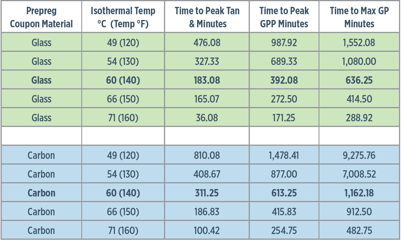
Table 1. This table shows the time in minutes for each coupon to reach peak tan delta, peak dissipative loss modulus (Gpp) and maximum elastic storage modulus (Gp) for each material at each of five different isothermal temperatures. Note that the glass fiber coupon took 636.25 minutes (10.6 hours) while the carbon fiber took 1,162.18 minutes (19.4 hours) to reach max Gp at 60°C (140°F). The time to max Gp was the recommended time for a safe initial cure. Source: Abaris
The beauty of using the MSM software, along with the ESR, is that we can send thermal sensor data from an actual curing part located inside the oven or autoclave and view the viscoelastic properties (read “Ensuring cure: Viscoelasic feedback”) from a parallel sample coupon of the same material that is running in the rheometer. This gives visibility to the otherwise hidden properties that are assumed when running the legacy cure recipe. Instead, MSM is designed to manage the time and temperature parameters to control the state of cure of the part. Reference ASTM D7750 “Standard Test Method for Cure Behavior of Thermosetting Resins by Dynamic Mechanical Procedures using an Encapsulated Specimen Rheometer” as a guideline for use.
The technology and equipment mentioned above has greatly improved since
inception. It has allowed us to evaluate numerous materials over the years and is best suited for use in streamlining production and MRB activities, as well as cure model development (read “Automating and optimizing autoclave cure”). It shows promise for use in a number of areas including inspection testing of incoming materials and reduction of cycle time to save energy. There are many more possibilities — too many to mention in this short column. I encourage those in industry to learn more about these systems for use in their own facilities.
Reference
1. First generation ATD-2000 ESR, manufactured by Alpha Technologies, Akron, Ohio. (The equipment has since been superseded with a new generation ESR as shown.)
2. CSS 300 PACE system AvPro Inc., Norman, Oklahoma. (Since superseded by the CSS 400 system.)
3. E-glass, Style #7500, 42 % nominal fortified resin volume (43 wt% NS
content).
4. T700 carbon, 670 gsm 2/2 Twill, 42% nominal fortified resin volume (43 wt% NS content).
5. Presented at SAMPE Tech in 2013, “Effect of Nanosilica on Thermal and Rheological Properties in Processing of Epoxy Impregnated Tooling Prepreg.”
.jpg;maxWidth=300;quality=90;format=webp)


Related Content

Chantiers de l’Atlantique reveals 66-meter, all-composite SolidSail mast
A technological feat, the large carbon fiber mast prototype targets the Silenseas sailing liner and sailing cargo ships for up to 40% reduction in CO2 emissions.
Read More
Mikrosam, H2Storage collaborate on 300+-liter Type IV hydrogen tanks
Automated filament winding cell achieving wind speeds of 6 meters/second improves production performance, shortens curing cycle for serial production of 700-bar Type IV tanks.
Read More
SmartValves offer improvements over traditional vacuum bag ports
Developed to resolve tilting and close-off issues, SmartValves eliminate cutting through vacuum bags while offering reduced process time and maintenance.
Read More
Nine factors to consider when designing composites cure tooling
Gary Bond discusses the common pitfalls and compromises when designing good cure tooling and their holistic significance for a robust composite production process.
Read MoreRead Next

Measuring temperature inside composites and bondlines
ThermoPulse sensors offer Industry 4.0 temperature measurement and digital cure cycle management for bonded composite repairs, laminates and more.
Read More
Alternate heat sources for hot-bonded composite repairs
Successfully using an alternate heat source for repairing composite structures requires an awareness of thermal dynamics and effective heat transfer management.
Read More
CW’s 2024 Top Shops survey offers new approach to benchmarking
Respondents that complete the survey by April 30, 2024, have the chance to be recognized as an honoree.
Read More