


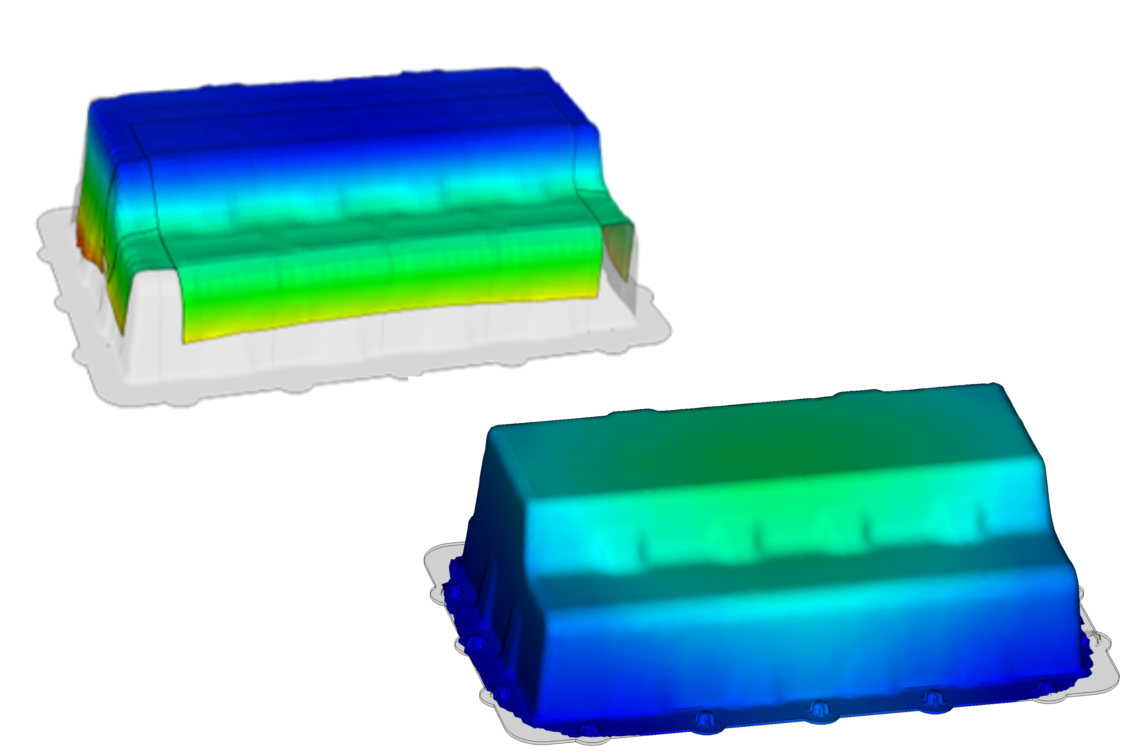
On the top left is the result of the pre-draping simulation of the complex initial SMC charge, which served as a baseline for subsequent moldfilling simulations. On the bottom right is an intermediate result of a moldfilling simulation after pressure is applied and material has flowed. Photo Credit, all images: Simutence GmbH
A team of companies in China and Europe led by HRC Group (Changshu, China) have been working on a multipronged feasibility study for a new battery module concept for electric vehicles. Details covering one design aspect of the study were previously discussed in CW’s February 2022 Focus on Design, “SMC material configurations tailored to automotive battery enclosure design.”
Malnati: Simutence uses some interesting CAE tools to predict forming behavior of both thermoset and thermoplastic composites. How did you get involved in this project?
Fengler: I’ve known Timo Huber, vice president of HRC’s Advanced Composite Technology Center (ACTC), for more than 10 years. In fact, we visited him and his team in China in 2018. ACTC had been planning a grand opening for their new facility in China in 2020, and we were invited to speak about composite simulation at the event. In preparation, we ran a series of draping, moldfilling and warpage simulations on the battery cover, which was supposed to be the demonstrator part to be manufactured during the opening ceremony. Unfortunately, the opening was canceled due to the pandemic, but we ended up teaching a couple of one-hour webinars on our work that got people interested in what was done.
Malnati: Can you give us an overview of what you did on the HRC battery cover?
Fengler: For this project, we focused on moldfilling, warpage and assembly simulations using modeling approaches we’ve developed ourselves. An interesting aspect, which was developed for this particular project, is simulation of the pre-draping of the initial charge, which we performed owing to the complexity of the initial SMC charge configurations being used to manufacture the part. We then applied those models to different initial charge configurations with the two SMC materials — with glass fiber and carbon fiber — to see what was possible in terms of filling the tool and, therefore, the required press forces. We found that both materials behaved with the same basic mechanics, although they yielded different absolute values. Given that similarity, we focused subsequent efforts just on GF-SMC
Malnati: Was there any concern about simulating possible movement of the prepreg strips during loading of the SMC ply stack and then molding?
Fengler: By the time we got involved, the decision had already been made to B-stage/precure the prepreg strips in the same tool before the SMC ply stack was added, so we didn’t have to worry about the tapes moving during SMC forming. What we did do is run draping models for the initial SMC charge to get an idea about what kind of initial geometry was created after placement of the initial charge in the lower tool half.
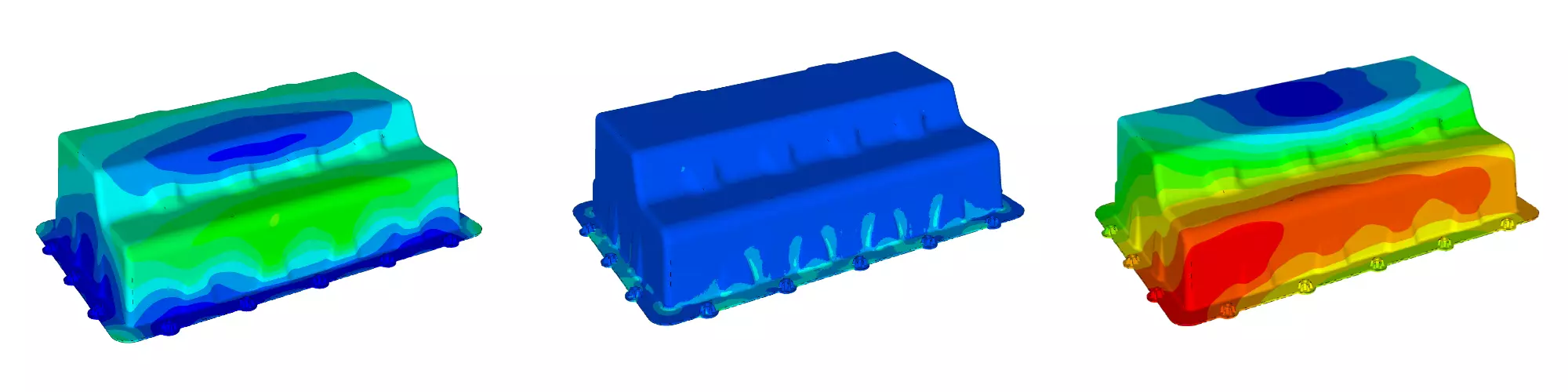
In order to demonstrate the influence of the fiber orientation on subsequent simulations within a virtual process chain, we first ran an isotropic warpage simulation to predict process-induced deformations, followed by a simulation considering the fiber orientations from the moldfilling simulation. By comparing the results, we were able to demonstrate a significant influence of fiber orientation on the process-induced deformations — particularly warpage. Based on these simulations, we ran an assembly simulation to see what happens when the battery cover was assembled to the car structure. The aim was to analyze the influence of warpage on the residual stresses that were created when the part is forced by the assembly points into the correct position. Not surprisingly, we found locally high stresses in the locations where the bolts join the base to the cover. If you run a typical workflow, you’d expect to find the part completely stress-free in an assembled state. Only if you run an assembly simulation would you be able to find out that wasn’t the case. These pre-tensions in the material might cause your part to fail sooner than you’d expect during the actual use.
Malnati: Is assembly simulation something that Simutence developed or is it part of typical moldfilling codes?
Fengler: Well, we didn’t invent it, but for some reason it’s not part of the typical workflow. From our point of view, it should be used during the development phase since this allows a more accurate prediction of the performance of the final part. I suppose in the predevelopment phase like the HRC battery cover, it’s not considered as big an issue as it would be when moving to serial production. The basic process isn’t that hard to do. You run a warpage simulation to gain the information on the process-induced deformations, then transfer the results into your structural analysis model, where you virtually assemble the components. Additionally, you need to map the results of the moldfilling simulation — in that case, the fiber orientations — onto the assembly simulations. With this process, you would be able to consider the effect of process-induced deformations, and therefore, the effects of shrinkage and thermal expansion due to the matrix and reinforcing fibers, as well as their resulting stresses during assembly.
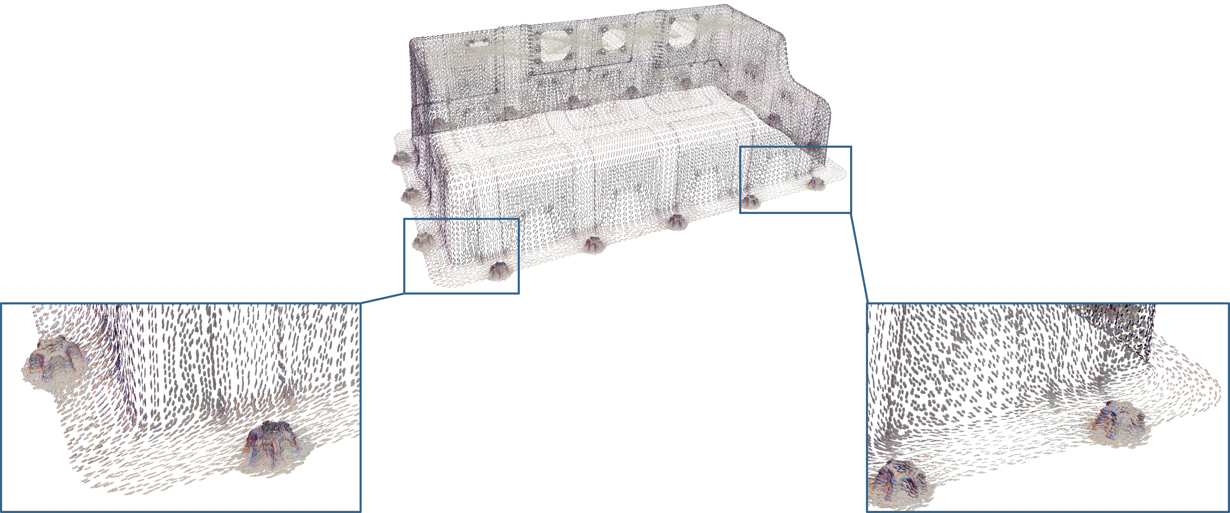
Fiber orientation predictions from the moldfilling simulation showing fiber alignment due to material flow.
Malnati: I understand that another thing Simutence looked at is friction modeling. Can you tell us a bit about that and why it was necessary?
Fengler: Friction modeling in the context of moldfilling simulations focuses on the description of the interaction of the tool surface and the composite material. Especially for SMC, it is essential to describe the lubrication layer at the interface of the steel and the SMC, since this has a significant influence on the flow and moldfilling behavior. From a modeling perspective, this is also the seminal difference versus thermoplastic compression molding, where it’s reasonable to assume no wall slippage — that is, since the hot material solidifies quickly when it hits the cooler mold wall, it’s assumed not to slip down the wall as a still-curing thermoset material like SMC might. This difference is often neglected and, at the same time, is one of the reasons why some of the available simulation approaches for SMC molding don’t yield accurate results.
Malnati: Is this lubrication layer the mold release that’s sprayed on the tool every so many molding cycles?
Fengler: In this case, it’s more an internal cause than an external mold release. You’re essentially looking for resin-rich areas at the tool surface around the core region where you would have no fibers. That’s what’s creating the lubrication layer.
Malnati: Is there anything special about your approach to simulating friction and lubrication in filling analyses?
Fengler: What’s new in our approach is that we model the friction between the SMC charge and the tools to account for the special lubrication layer. Moreover, having a slip condition at the walls forces the SMC into a so-called plug flow where, besides the classical shear viscosity, the elongational viscosity plays a major role. In contrast to other approaches, we consider the shear and elongational viscosity in both modeling and material characterization. Apart from that, I’d say we are in line with other approaches not considering curing during molding. This is reasonable for the manufacturing strategy pursued in the project with HRC, which had a relatively fast fill time of five seconds or less. The rest of the molding cycle is spent on curing.
Therefore, we first run a simulation, assuming no curing during moldfilling, and then used a subsequent simulation step to predict curing and warpage. Here, the fiber orientation from moldfilling is considered. The material is not flowing 100% symmetrically for HRC’s battery cover, and fiber orientation is not symmetric, yielding process-induced deformations, along with warpage. If we’re brought in early enough, we can use this kind of information to help guide the initial workflow and positioning of the initial charge configuration to more accurately account for material flow and fiber orientation. You’d recheck the structural performance, then maybe adjust by adding a slightly larger or smaller charge in your next filling simulation.

Simulation results on the left show deviation between actual and nominal geometry considering warpage and assembly. Local stresses due to part assembly are indicated by the middle image (ote higher stress areas around the bolt locations). The far right indicates deviations between actual and nominal geometry with respect just to warpage.
Malnati: Since in-depth analyses focused on GF-SMC, is there anything you think would have been interesting to consider about carbon fiber SMC if there had been time?
Fengler: Since the CF-SMC used in the study had a higher fiber weight fraction (FWF) than the GF-SMC — I think it was 53 versus 40 wt% — and the initial charge coverage of the tool was roughly 90% for CF-SMC versus 60% for GF-SMC, we’d have expected to see a higher impact of the initial charge’s fiber orientation for the carbon fiber SMC because it will flow less than the glass fiber SMC. Investigating this in both molding and warpage simulation would have been highly interesting.
Malnati: Is there anything else that might have been interesting to look at if time had allowed?
Fengler: As noted earlier, we didn’t consider the prepreg strips in moldfilling simulation, but it would have been interesting to look at squeeze flow of SMC over and around the tapes and the possibly induced deformation and displacement of the strips. In order to do that, a fluid-structure interaction between tapes and SMC is necessary. This can be done using an approach that was developed during the doctoral studies of Simutence’s co-founder Martin Hohberg. It would have been interesting to see if the predictions suggested that the tapes affected the flow of the SMC as it filled the tool or if certain processing conditions can yield a deformation of the strips.
Malnati: Is there anything you feel our readers should understand about process simulation of composites?
Fengler: The most important point about running simulations on SMC or any composite, is to consider the manufacturing process during simulation. Molding causes fiber reorientation, and orientation leads to anisotropy and can cause additional warpage. Moreover, the part’s structural performance is significantly influenced by manufacturing effects. Thus, it’s more challenging to predict how composites will behave than it is with metals, which are mostly isotropic. That’s why it’s important to develop accurate models for the manufacturing process in order to be able to predict manufacturing effects, which in turn enable more accurate predictions about warpage and structural performance. It’s not just about simulating structural performance.
Materials and process decisions for this project are explained more in-depth in “Hybrid battery cover: Materials, process decisions.”


.jpg;maxWidth=300;quality=90;format=webp)
Related Content

Optimized approach to predict delamination failure in CFRTP structures
ARRK Engineering and Mitsui Chemicals improved delamination prediction accuracy to help optimize absorbed energy/failure load for an overmolded TAFNEX CF/PP UD tape bumper beam.
Read More
Jeep all-composite roof receivers achieve steel performance at low mass
Ultrashort carbon fiber/PPA replaces steel on rooftop brackets to hold Jeep soft tops, hardtops.
Read More
SuCoHS project: Advancing composite solutions for parts with high thermal and mechanical loads
New materials, structural concepts and manufacturing using sensors for composites that resist fire, temperature and loads while providing weight and cost savings versus metals.
Read More
Thermoset-thermoplastic joining, natural fibers enable sustainability-focused brake cover
Award-winning motorcycle brake disc cover showcases potential for KTM Technologies’ Conexus joining technology and flax fiber composites.
Read MoreRead Next

From the CW Archives: The tale of the thermoplastic cryotank
In 2006, guest columnist Bob Hartunian related the story of his efforts two decades prior, while at McDonnell Douglas, to develop a thermoplastic composite crytank for hydrogen storage. He learned a lot of lessons.
Read More
Composites end markets: Energy (2024)
Composites are used widely in oil/gas, wind and other renewable energy applications. Despite market challenges, growth potential and innovation for composites continue.
Read More
CW’s 2024 Top Shops survey offers new approach to benchmarking
Respondents that complete the survey by April 30, 2024, have the chance to be recognized as an honoree.
Read More