


Photo Credit all images: SuCoHS project
The project Sustainable & Cost Efficient High Performance Composite Structures (SuCoHS) began in September 2018 and held its concluding workshop on February 22 and February 23, 2022. Its objective was to expand the use of composites in aircraft applications subject to high mechanical and thermal loads, aiming for reduced weight and cost with improved performance and efficiency. The topics covered were extensive, from new structural designs and new materials to digital design and simulation of structural performance, mechanical, thermal and fire testing and certification, to use of sensors during automated fiber placement (AFP),cure and subsequent testing. The project culminated in three use case demonstrators and produced dozens of technical papers as well as the concluding 2-day workshop linked above.
The SuCoHS consortium included engineers and researchers from 14 partners in seven countries, including technical universities and research organizations, material developers and Tier 1 suppliers.
SuCoHS partners and roles
Technical universities: University of Applied Sciences and Arts Northwestern Switzerland (FHNW, Windisch) and Hamburg University of Technology (TUHH, Hamburg, Germany) supported material development activities and probabilistic analyses.
Research centers: German Aerospace Center (DLR, Braunschweig), Royal Netherlands Aerospace Centre (NLR, Marknesse) and the French Aerospace Lab (ONERA, Palaiseau) helped to investigate new material systems and manufacturing technologies, perform structural testing for phenomenological analysis, develop related material models and derive new structural analysis methods and design concepts.
Tier 1 suppliers: Aernnova, Collins Aerospace Composites Centre of Excellence (Kilkeel, Northern Ireland) and Spirit AeroSystems (previously Bombardier, Belfast, Northern Ireland).
Materials suppliers: Transfurans Chemicals (Geel, Belgium) for polyfuryl alcohol (PFA) resins and North Thin Ply Technology (NTPT, Renens, Switzerland) for thin-ply prepregs.
Nondestructive testing (NDT) and sensor suppliers: Apodius (Aachen, Germany) part of Hexagon Manufacturing Intelligence (Cobham, U.K.) which left the consortium in 2019, Synthesites (Uccle, Belgium) and PhotonFirst (previously Technobis, Alkmaar, Netherlands).
The SME grant management firm L-UP (Paris, France) assisted the consortium with project management, communication and dissemination.
Origin of a comprehensive project
“We had been in contact with quite a few of the consortium partners for some time, especially with the Tier 1 suppliers,” says Tobias Wille, head of Structural Mechanics at DLR (Braunschweig, Germany) and SuCoHS project coordinator. “The focus in SuCoHS was on structures that are loaded not only mechanically but also under high thermal conditions and need for fire resistance. We wanted to understand why it is so hard to introduce composites to such structures. Is there a way to reduce conservatism while ensuring safety? Can we introduce new materials and/or new designs? Is it a matter of manufacturing technologies that have to be adapted or are the issues more with testing and certification requirements?” This is why the overall project had to be so comprehensive, he explains. “We didn’t say the solution was to develop a new material or manufacturing process, but instead that we needed to capture the whole story from the early design stage through to certification testing. And that's how we developed the project’s main objectives.”
An example of the wide development within SuCoHS, in this case, for an aircraft seat shell. Photo Credit: Collins Aerospace presentation, final SuCoHS workshop.
The Tier 1 supplier partners defined the end use cases which became the project’s three demonstrators, which helped guide the project’s organization. “They defined in-use temperature and load requirements and what their needs were as manufacturers. We then began exploring what could be improved and tried to identify the major common issues and possible solutions.”
“We came with some ideas and also received ideas from other partners about materials that could possibly be used in such structures,” adds Wilco Gerrits, senior R&D engineer and SuCoHS program manager at Royal Netherlands Aerospace Centre (NLR, Marknesse). “We discussed what could be feasible for manufacturing, and one key task was to check feasibility of the concepts and to close the innovation gap to achieve a higher TRL (technology readiness level) for such structures. Through the use cases, we were able to demonstrate two new materials for lightweight, high-temperature composite aircraft structures.”
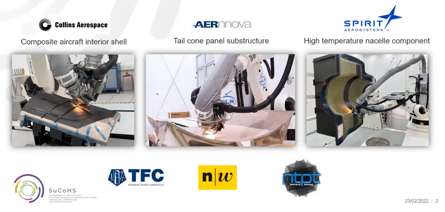
Photo Credit: SuCoHS project final workshop, presentation by Wilco Gerrits
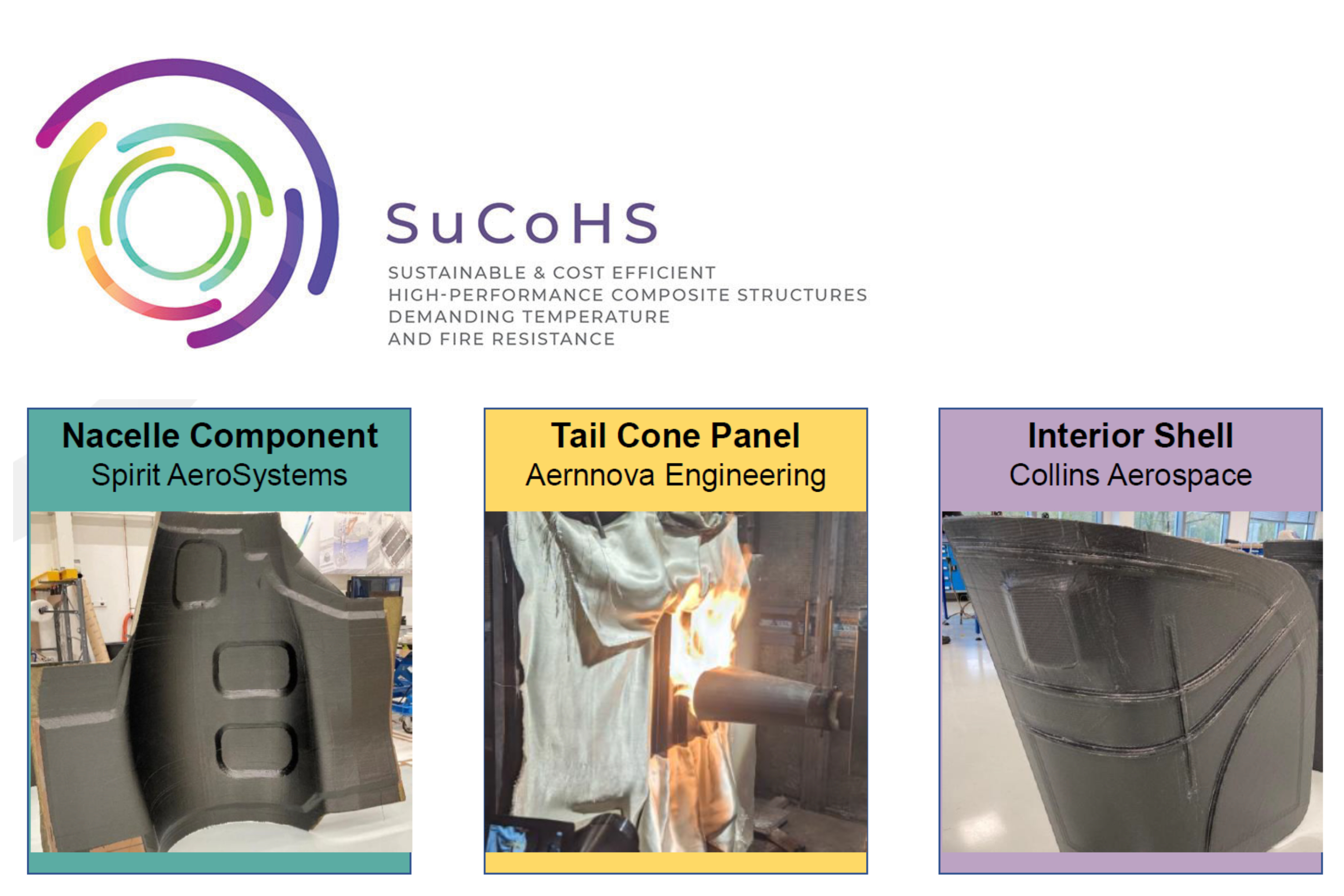
Three use case demonstrators
Aernnova provided the large rear fuselage shell, which must comply with fire requirements due to the auxiliary power unit (APU) inside. Collins Aerospace provided an aircraft interiors use case — a seat structure that has to withstand specific fire and crash load requirements. The third use case was an engine nacelle inner structure proposed by Spirit AeroSystems in Belfast. The main drivers for each use case demonstrator include:
Aernnova tail cone panel substructure
- Avoid titanium APU housing
- Temperatures >300°C
- Ensure fire resistance and damage tolerance
Collins Aerospace seat shell
- New structural design and materials for improved performance at reduced cost
- Flammability, smoke and toxicity (FST) requirements for aircraft interiors
Spirit AeroSystems aeroengine nacelle inner fixed structure (IFS)
- Reduce part complexity and subcomponents
- Multifunctional requirements and loading
- Temperatures >335°C
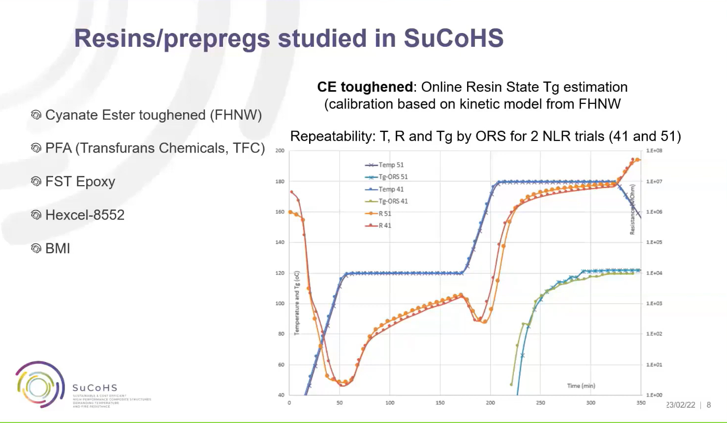
PFA and new cyanate ester materials
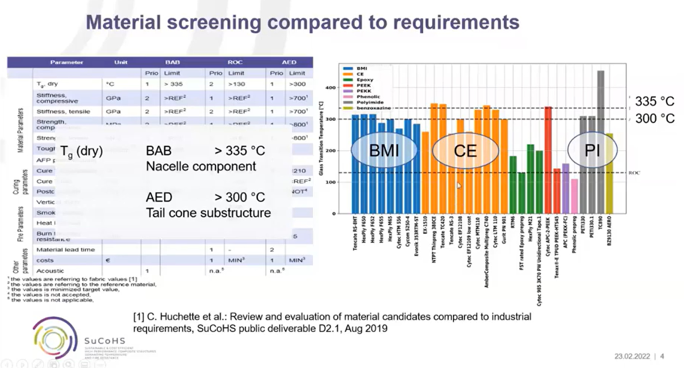
Evaluation of high-temperature resins for composites including polyimide (PI). BAB = Bombardier Aerospace Belfast, now Spirit AeroSystems and AED = Aernnova. Photo Credit: SuCoHS final workshop presentation.
The beginning of SuCoHS included a materials screening phase. “We could not demonstrate all materials that might be of interest,” says Wille, “so we used our partners’ competencies to downselect to PFA [polyfurfuryl alcohol] and a new, toughened cyanate ester (CE) for deeper investigation. We also tested some of the currently used reference materials, like epoxy, phenolic and BMI [bismaleimide] where we had gaps in our knowledge.” Note, FST/high-temperature epoxy was considered another key baseline material.
Interest in PFA resins has been growing in rail and mass transit applications because it offers the temperature and fire resistance of phenolics but with improved sustainability, being derived from biomass (see Bio-based FR prepregs section of “Withstanding fire without the weight”).
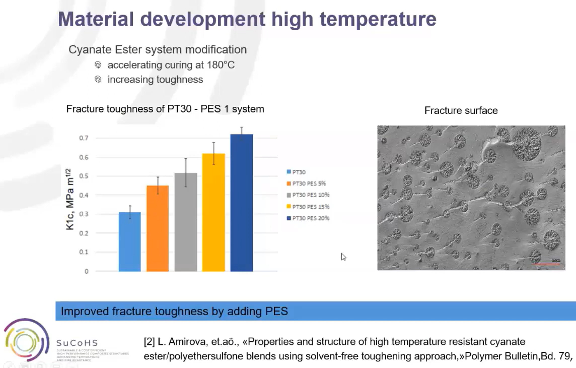
FHNW showed a >200% increase in KIC fracture toughness for its thermoplastic modified CE resin. Photo Credit: SuCoHS final workshop presentation.
Cyanate ester (CE), meanwhile, has been shown to offer high-temperature performance similar to BMI with processing similar to high-temperature epoxies. However, it has historically suffered from issues of brittleness and microcracking.
“FHNW University developed a technology to add polyethersulfone (PES) thermoplastic (TP) as a toughener to reduce this issue,” says Wille, “so we proposed to further investigate this material.” According to FHNW, their toughened CE more than doubled KIC values versus the untoughened baseline and can provide cure in 3-4 hours at 180°C. One of many challenges was that viscosity typically increases when adding TP tougheners, so this had to be balanced when devising how to make a prepreg tape and one with the right tackiness level required for AFP (see below).
“The first part of the program investigated what properties we could attain with these new materials, as well as testing material forms and combinations,” says Gerrits. “With these properties, we were able to begin adapting the materials to find solutions for the three use cases.”
AFP processing
Use of AFP for orthogrid stiffeners. Photo Credit: NLR presentation, SuCoHS final workshop.
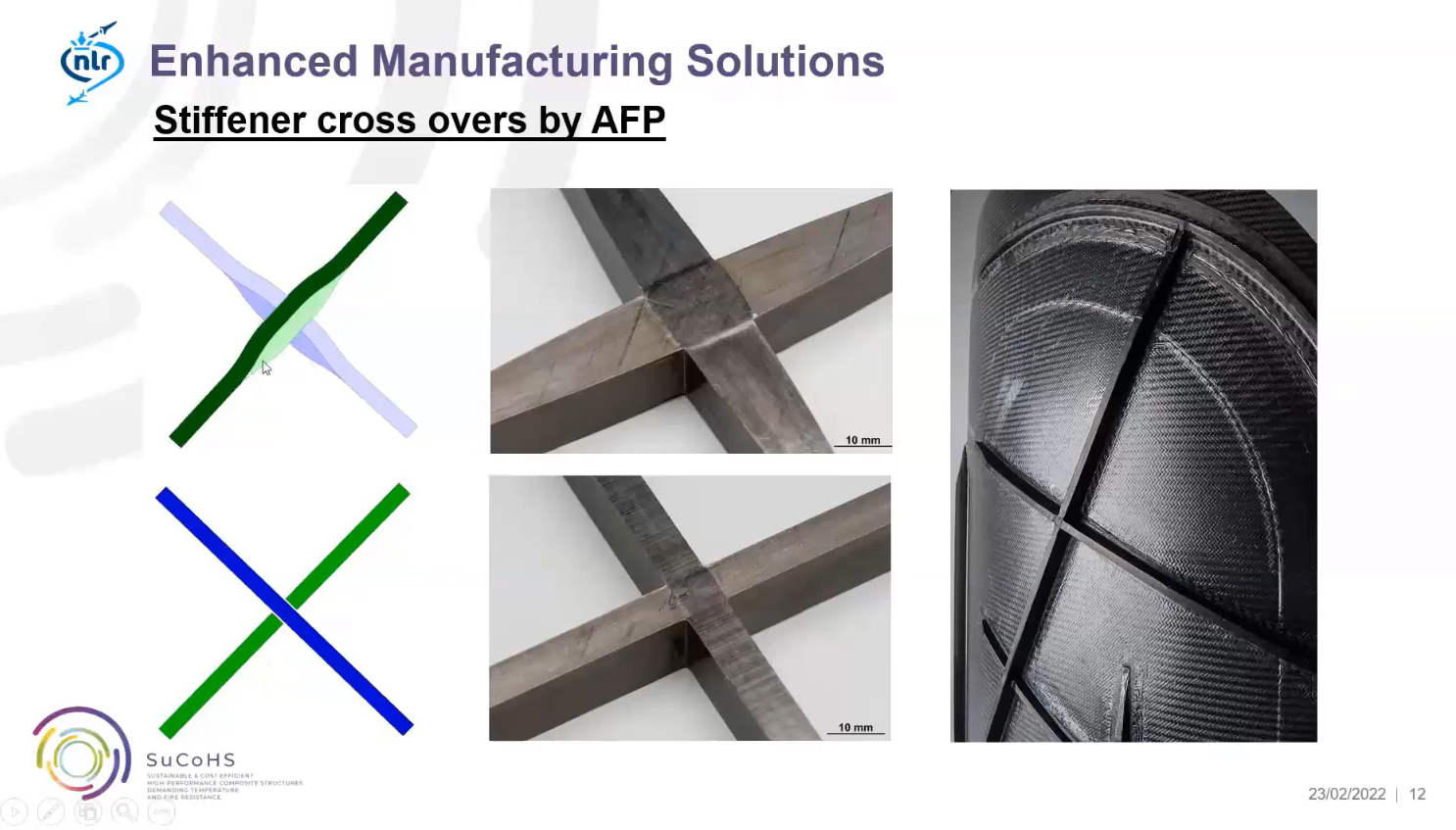
AFP was used in the production of all three demonstrators because it offers automation to reduce cost and improve performance. “It enables higher complexity shapes versus automated tape laying (ATL),” says Gerrits, “using multiple narrow tapes versus a lower number of wide tapes. This, in turn, enables fiber steering, which provides a lot of flexibility. For example, you can also use from one to eight tapes [on NLR’s Coriolis C1 AFP machine] and can achieve a true conical shape without cutting fibers mid-span.” He noted that AFP is also an efficient method to create orthogrid stiffeners, which NLR demonstrated in the ACASIAS project (see “Integrating antennas into composite aerostructures”).
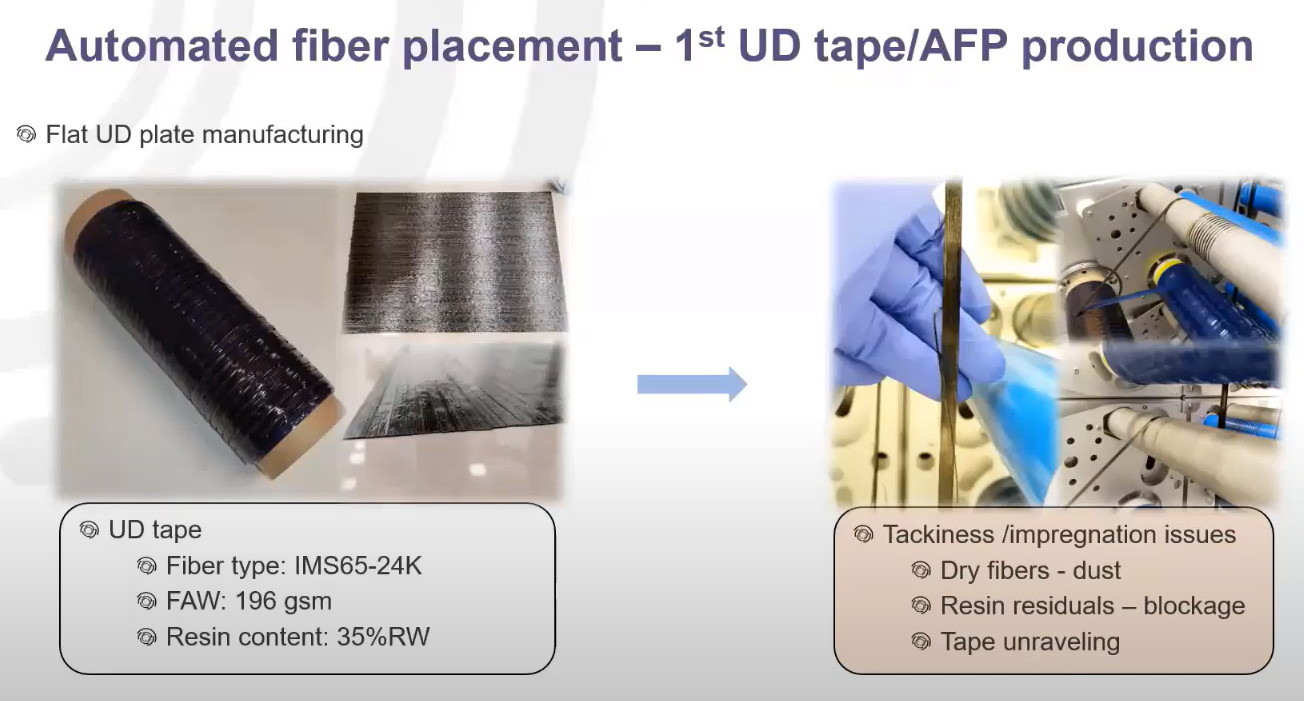
However, neither of the materials chosen for the study had been used in AFP before. Thus, a significant amount of development work was required. As FHNW began exploring how to convert its resin into unidirectional (UD) tape prepreg for AFP, it turned to nearby (2-hour drive) NTPT, a prepreg supplier that specializes in spread-tow, thin-ply materials. By spreading a normally round carbon fiber tow flat, it is possible to create thinner plies of prepreg that have been shown to offer higher specific properties (strength and stiffness divided by weight) and reduced crack propagation for more impact resistant and damage tolerant laminates (see “The spread of spread tow”).
The CE system was successfully converted into a thin-ply prepreg with an areal weight of 67 grams/square meter. This was not easy, notes Gerrits, “but the team was able to find solutions that also provided an acceptable process window for AFP. One of the things that is always troublesome is the tackiness of the material. You need sufficient tack to keep it in position, but if you have too much tack, it will create pollution in the machine and tape guides, which will causes trouble during placement. So, the B-staging of the prepreg had to be optimized, and then with this basis, we were able to define the best balance between the amount of compaction force, heating and the placement speed. In the end, we achieved high-quality layups with almost no contamination to the AFP machine.”
Another challenge for the thin-ply tape in particular was at the start of the fiber placement process. “There is 90 millimeters of free air across which the material is tensioned between the tape feed and the nip point where it is applied by the roller. But the thin ply prepreg is less stable than a normal tape, so starting is a bit tricky. Overall, it ran very well and showed good material properties.”
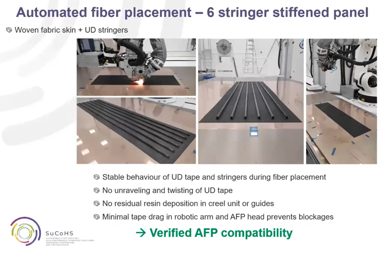
First trials of PFA UD prepreg tape (top) and AFP trials of UD stringers onto woven fabric skin for 6 stringer stiffened panel at NLR (bottom). Photo Credit: TFC presentation, SuCoHS final workshop.
The PFA prepreg was developed from a second-generation resin developed by SuCoHS partner Transfurans Chemicals (TFC). TFC had made hot-melt fabric prepreg previously, but now needed to develop a UD tape prepreg for AFP. Its first trial material had issues with tackiness, fiber separation and pollution in the AFP head. This was solved by increasing the molecular weight of the PFA system in the prepreg tape. AFP trials on a six stringer-stiffened panel element were completed at NLR using a 140 gram/square meter prepreg of normal thickness (not thin-ply).
There were also issues to consider with regard to material handling and cure, notes Wille. “When these materials were finally applied to the use case structures, there were issues with moisture uptake in the CE prepreg during storage. So, these issues had to be investigated to define the right handling and processing procedures.”
Flexible cure cycles
Both the PFA and toughened CE prepregs can be cured in a single cycle without post-cure. “But FHNW also defined a two-stage scenario,” says Wille, “in case a manufacturer’s autoclave can’t apply the maximum temperature, for example. In that case, a two-stage curing process could be used for the CE system, which could also be done in an oven. You could also use an autoclave and oven, to perhaps better balance energy consumption — pre-cure in an autoclave for good consolidation and then a second cycle in an oven with perhaps several parts at once. Each manufacturer could fine-tune the process to provide the best solution for them.”
“We also tried to find the limits of the materials,” add Gerrits. “For example, in one of the first tests with the cyanate ester material, we cured at 300°C and higher, to test the extremes. We did find some issues there, but we were able also to find solutions, and fine-tuned the in-service temperature produced in the cured part.”
Testing and sensors
A wide variety of mechanical and fire/thermal testing was performed during the project. “We pretty much followed the normal building block approach,” says Gerrits, “going from coupons to structural details and elements, including risk mitigation structures, and then to demonstration structures. But we didn’t complete the normal amounts of tests required for certification.”
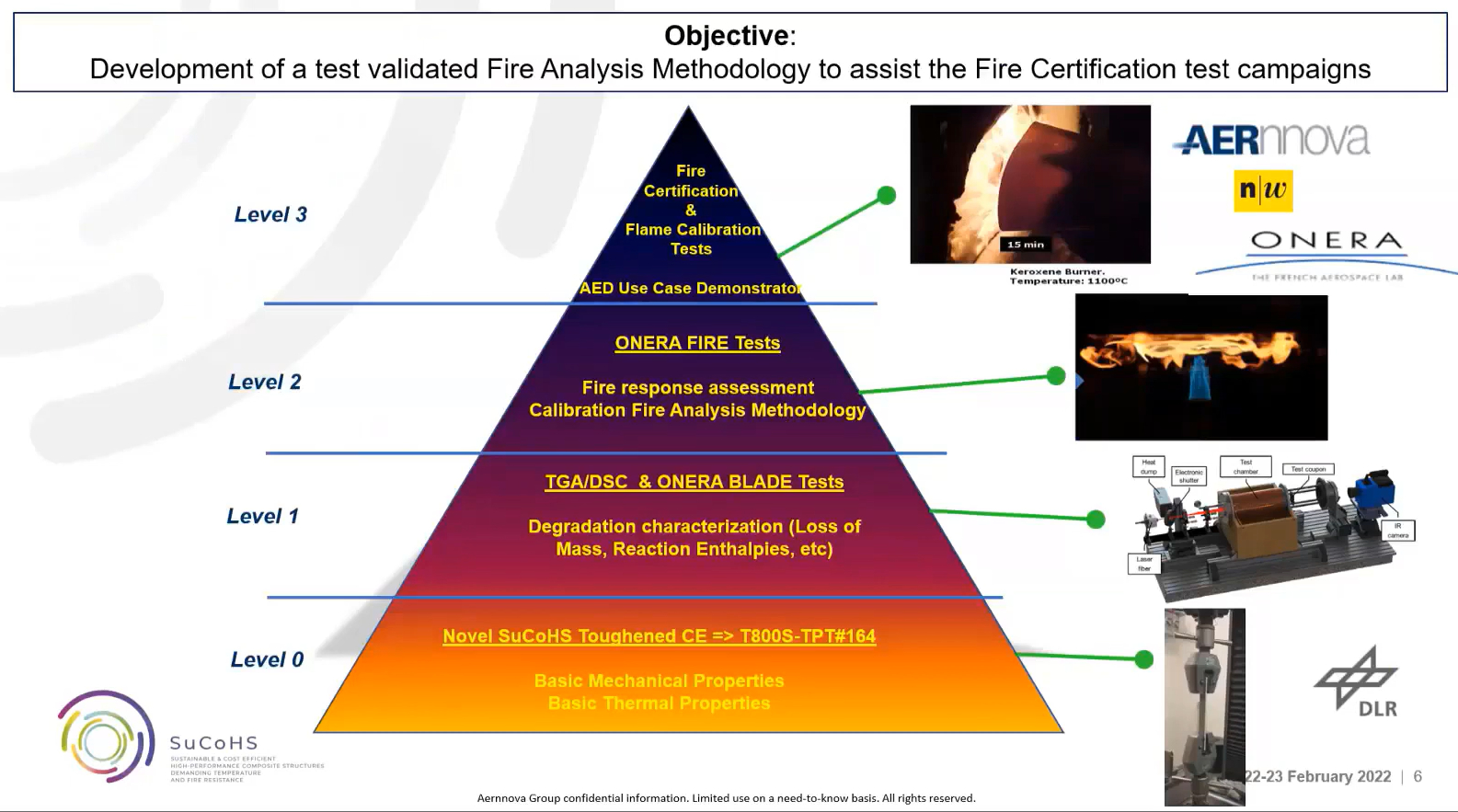
Examples of building block testing applied to fire testing and analysis in the SuCoHS project. Photo Credit: Aernnova presentation, SuCoHS final workshop.
“On the coupon level, we were looking to have at least five repetitions per specimen in order to have a certain reliability of those properties in our design and modelling,” says Wille. “We then moved to the element level — certain beams, for example — and then up to the final demonstrator. For the Aernnova tail cone panel, we then performed fire testing. It was only a single panel that was tested under fire conditions and mechanical loads, but on the element level just below, which is a large coupon, there were also 20 coupons tested under equivalent fire conditions to determine mechanical properties and prove the behavior. So, it was not a full certification program, but just sufficient so that we and our industrial partners are confident that we have enough properties to give a trustworthy evaluation of the materials and designs.”
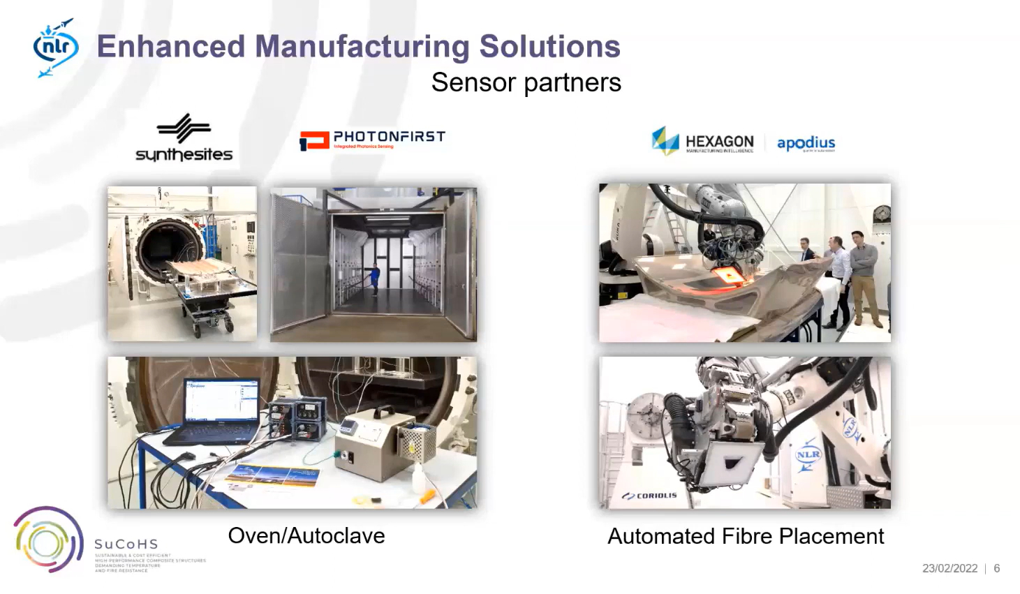
Sensor partners in SuCoHS. Photo Credit: NLR presentation, SuCoHS final workshop.
SuCoHS also tested the use of sensors during processing, working with three different partner technologies: PhotonFirst fiber optics with fiber bragg grating (FBG) sensors; dielectric sensors and monitoring from Synthesites, as well as the sensor-less Cure Simulator it developed during SuCoHS; and the Apodius sensor integrated into NLR’s AFP machine. “It is a shame that Apodius no longer exists as a company because that sensor and software system provided very good monitoring for defects and accuracy during fiber placement,” says Gerrits. “NLR has worked with many sensors for AFP, but the Apodius system was one of the best we have seen. It could inform about possible errors during AFP and even notify to do corrective measures to save material. The data it collected was then incorporated into a “central database”, says Gerrits, “which covered data to be exchanged between software packages, for example cure simulation and cure monitoring, simulation for the effects of defects and defect monitoring.”
Cure Simulator
Gerrits was also impressed with the Synthesites technology, an d NLR has since purchased a system. In a video during the final SuCoHS workshop, NLR showed the system being used to monitor resin arrival and cure during a BMI resin infusion process. “During SuCoHS, we used Synthesites disposable sensors on the parts and reusable sensors in the mold,” he says. (To learn more about these sensors, see “DC dielectric sensors for industrial composites production” and the CW sensors knowledge center). “In the last stage of the program, Synthesites developed the Cure Simulator, which is a really interesting piece of equipment. Using only one thermocouple (TC), the Cure Simulator can copy the cure process taking place inside the autoclave and determine the cure level of the composite to identify the point at which it is cured. This enables ending your autoclave process when it meets your cure requirements instead of keeping it at temperature for an extra half an hour just to be on the safe side.”
ORS calibration was completed for multiple resins during the SuCoHS project. Photo Credit: Synthesites
Described in the blog above, the standard Synthesites cure monitoring system comprises direct current (DC) dielectric sensors, Optimold data acquisition units and Optiview plus ORS software. The sensors measure resin temperature and electrical resistance, which is collected by Optimold and translated by ORS software into estimated resin viscosity and glass transition temperature (Tg) during cure. This requires calibration completed beforehand — creating temperature versus viscosity curves from rheometer testing samples of the specific resin to be monitored. Appropriate formulas are then applied to calculate corresponding resistance and Tg data for that resin. During SuCoHS, ORS software calibration was completed for the FHNW toughened CE, the TFC PFA and baseline materials including FST epoxy, Hexcel 8552 (toughened, 180°C cure epoxy) and Cycom 5250-4 BMI from Solvay (Alpharetta, Ga., U.S.).
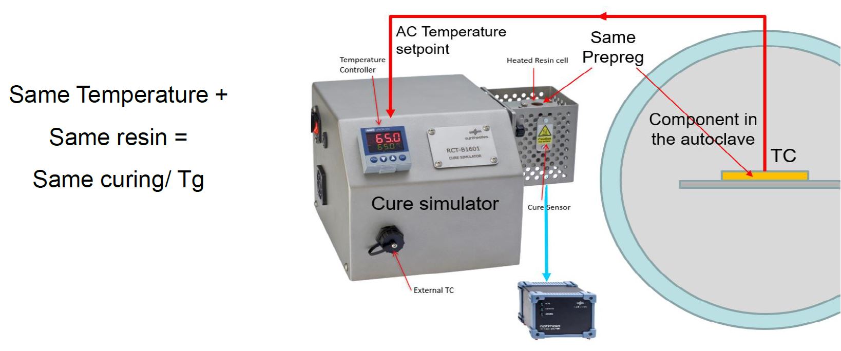
Photo Credit: Synthesites
The Cure Simulator operates on the same principles, using a fixed, reusable cure sensor onto which a prepreg is attached and then heated, controlled by the TC output from the autoclave. Synthesites demonstrated that the cure cycle applied to the part in the autoclave (Sim8-1 in image below) was copied by the Cure Simulator outside the autoclave using TC data (Sim8-2 in image below).
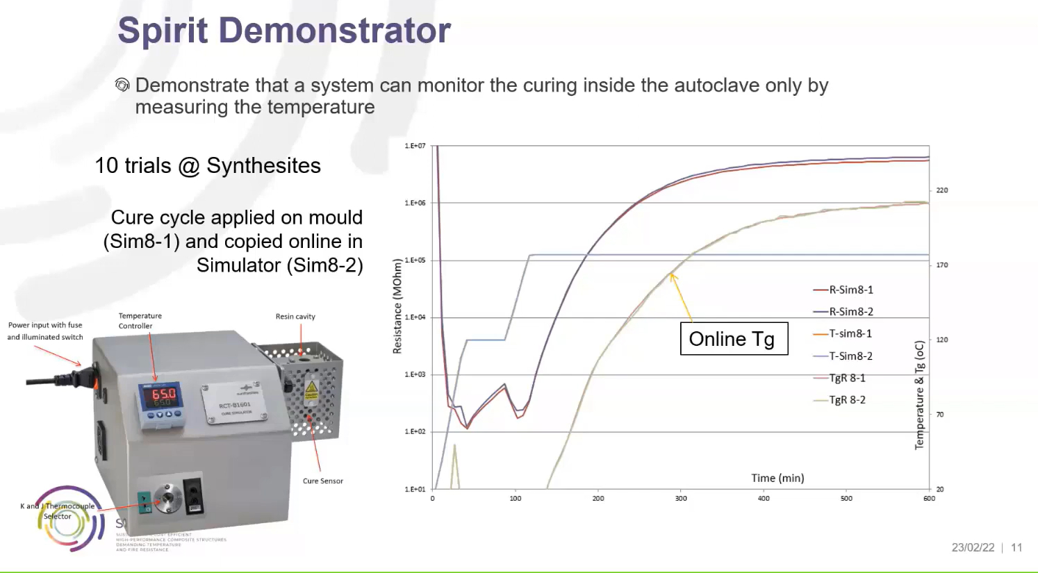
Photo Credit: Synthesites
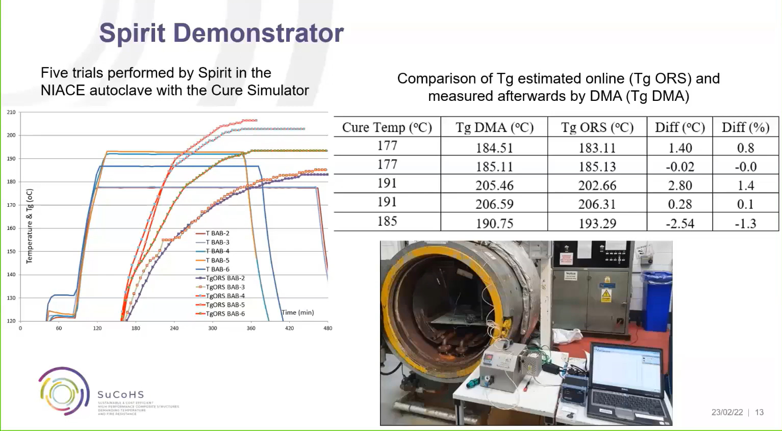
Photo Credit: Synthesites presentation, SuCoHS final workshop.
In further trials, Synthesites was able to show reliability in this method of cure monitoring (image at right) and that curing at 191°C instead of 177°C could reduce the cure cycle time by 50% to achieve the same Tg. During SuCoHS, Synthesites also used durable/reusable sensors that work with CFRP without the need for glass fiber insulation and disposable sensors that can work at 250°C.
For more details, see Synthesites Nov 2021 paper presented at SAMPE Europe. Also, multiple papers are available for download on the SuCoHS website.
AFP of fiber optic sensors
Cure monitoring was also achieved using optical fibers provided by PhotonFirst. “Each of these contained several FBG sensors that measure strain and temperature,” says Gerrits. “These sensors were very helpful during the cure process and also afterwards, during impact testing.”
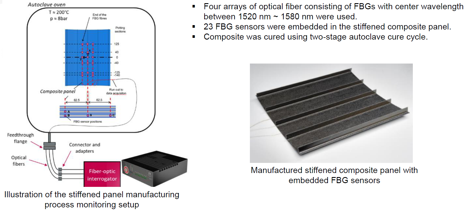
Photo Credit: PhotonFirst presentation at SAMPE Europe 2021 (top) and NLR (bottom).
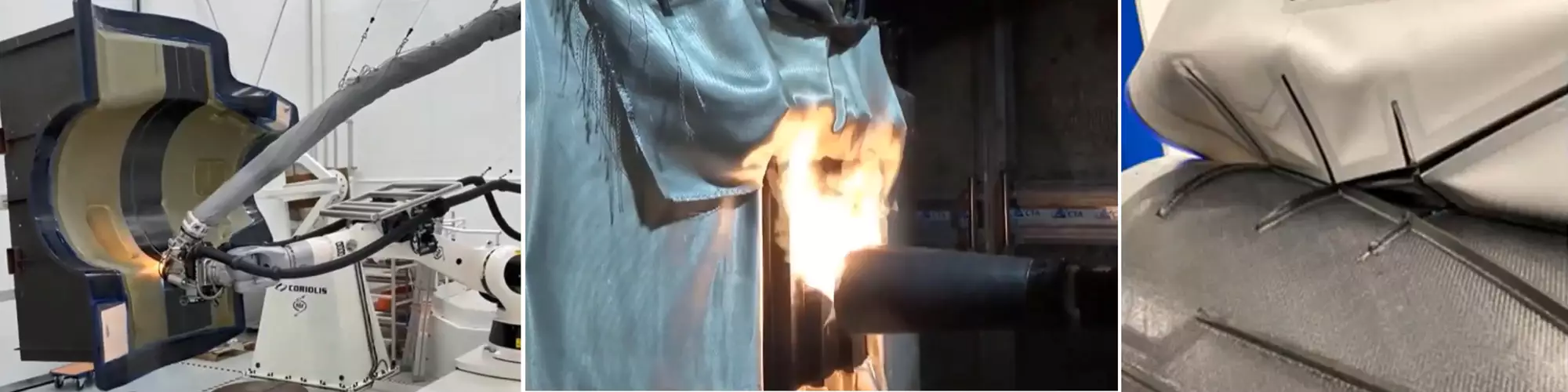
Perhaps the most significant achievement was use of AFP to embed the sensors into the Aernnova tail cone demonstrator. CW briefly reported on this in the March 2022 feature “Sensors: Data for next-gen composites manufacturing” and more details were provided by NLR during the final SuCoHS workshop. As can be seen at left, lane 8 of the NLR Coriolis AFP head was used to deposit the optical fiber. NLR first created a small gap in the AFP layup and then positioned the optical fiber there. As the layup continued, the fiber was embedded. “We did cure cycles on these initial small panel tests to make sure the sensor was fully embedded,” says Gerrits. NLR also devised using polyetheretherketone (PEEK) polymer tubes to protect the optical fibers as the exited the edge of the panel. “If you create repeated bends, you will get a signal loss in the transmitted light data,” he explains. NLR also developed 3D printed PEEK guides which were used to transition the fibers through tacky tape during vacuum bagging, protecting the fibers from bending and ensuring vacuum integrity in the bag.
Discussion and highlights, use case demonstrators
Although both the toughened CE and PFA UD prepregs were able to be applied to all three end use cases for fabrication of the final demonstrators, the actual materials used were decided by the Tier 1 suppliers. “We made investigations on both materials up to the demonstrator level, but different materials were selected for each demonstrator,” says Gerrits. The toughened CE prepreg was used to produce the Aernnova tail cone panel, the Spirit AeroSystems nacelle structure evaluated a reference BMI material, and although the PFA prepreg was demonstrated on an intermediate structure for the Collins Aerospace seat shell demonstrator, the final demonstrator was fabricated using a reference FST epoxy.
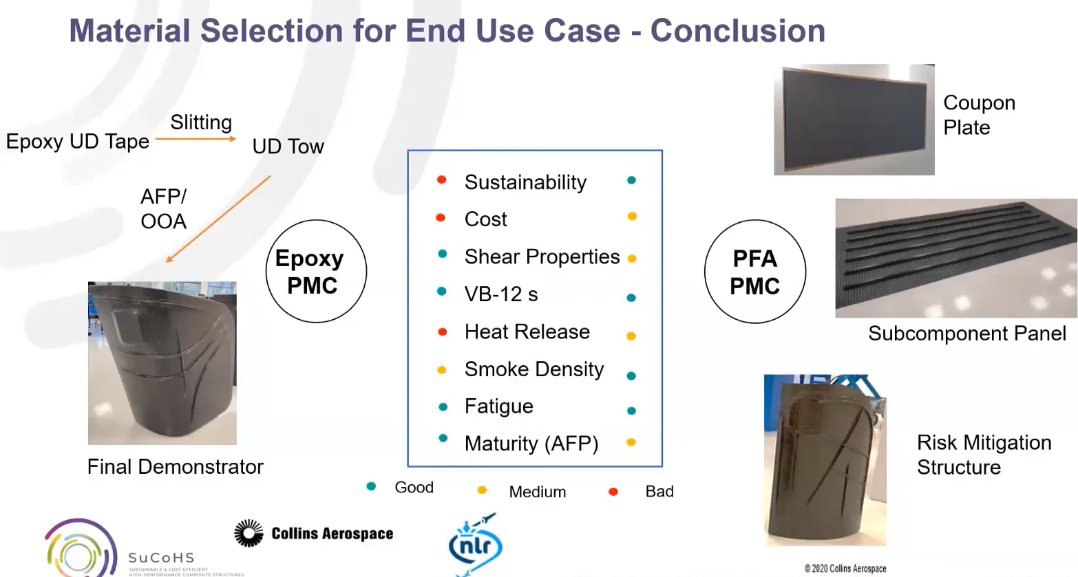
Collins Aerospace evaluation of materials for the seat shell demonstrator where PMC = polymer matrix composite. Photo Credit: Collins Aerospace presentation, final SuCoHS workshop.
Wille explains the intermediate structure for the Collins Aerospace seat shell and the final material choice. “This was what we call a risk-mitigation structure, which has the same size as the final demonstrator but not exactly the same design details. The issue with using the PFA in the final demonstrator was that its interlaminar shear strength (ILSS) was still not fully meeting requirements. Team members were trying to improve this in time for manufacturing the demonstrator, but there just wasn’t sufficient time. So, in the end, the team decided to use the reference material, to pass the following structural tests. But the PFA material is not out of contention, it just needs one or two more steps to reach the requested TRL.” He notes that even without further modification, Collins Aerospace has said the material has enough sustainability, cost and fire resistance advantages that they will find a solution to address the current 20% shortfall in ILSS so that it is possible to use this material in the future.
Nacelle inner fixed structure demonstrator
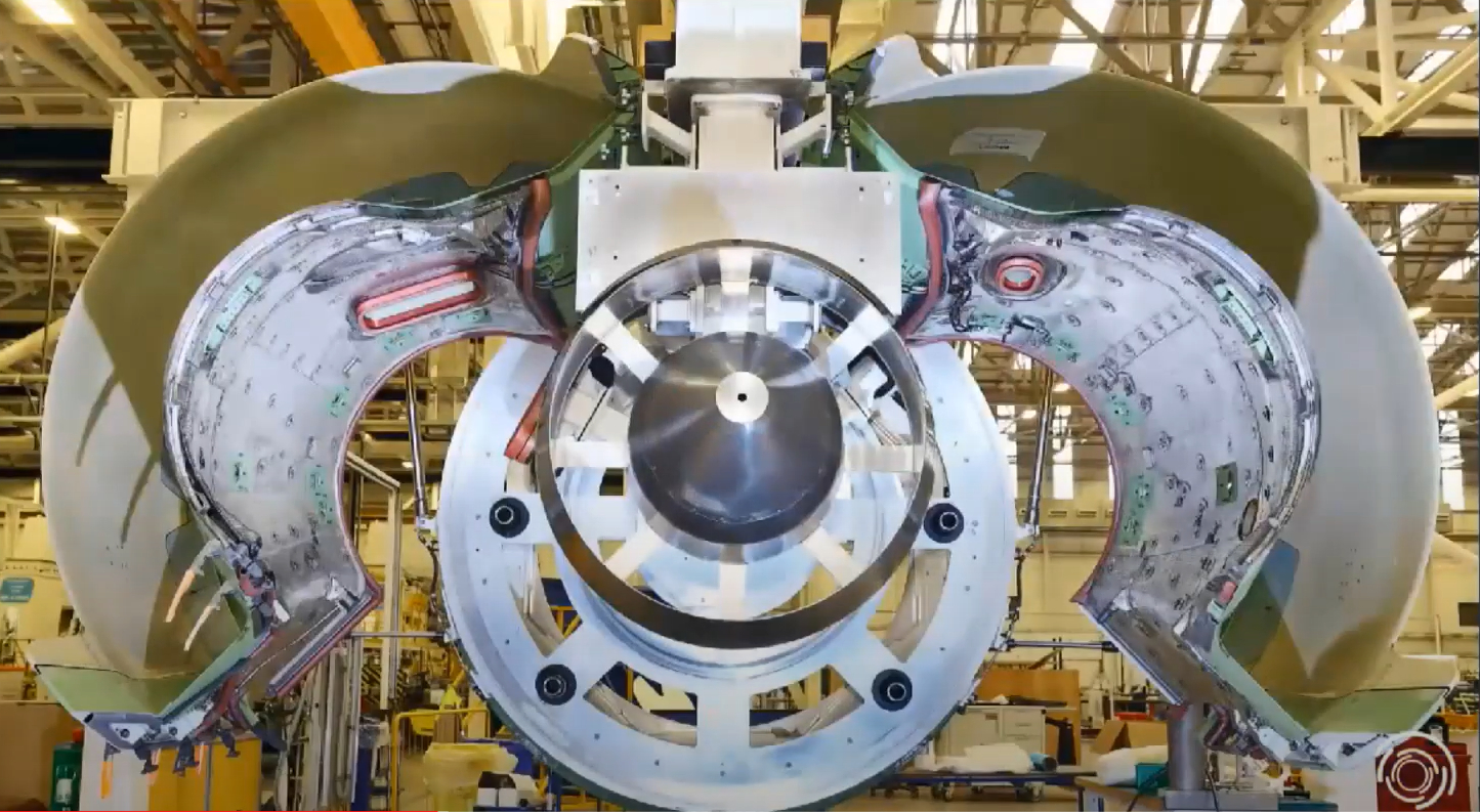
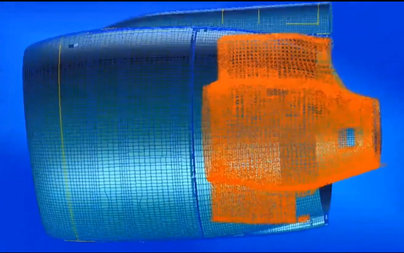
The left-hand and right-hand components of the nacelle inner fixed structure can be seen at top and its shape highlighted in orange in the CAD drawing at bottom. Photo Credit: Spirit AeroSystems Belfast presentation, final SuCoHS workshop.
In the SuCoHS final workshop, Daniel Breen, senior project engineer at Spirit AeroSystems Belfast, explained that this use case is an aeroengine nacelle inner fixed structure (IFS), made using composites, which is a structural part of the thrust reverser unit and comprises left-hand and right-hand components. For SuCoHS, only one side was demonstrated. It is a complex-shaped, aluminum honeycomb cored part that has multiple functions. It must have high specific strength-to-weight and provide excellent fatigue and vibration resistance. It also aids engine cooling by actively conducting heat from the hot engine side of the part to the cool side which forms part of the bypass duct. Thus, it also provides aerodynamic properties for this duct at the rear of the nacelle. Finally, and equally important, it provides acoustic dampening which is key to the engine noise attenuation it provides.
The goal for this demonstrator in SuCoHS was to reduce part count, improve fatigue resistance and noise attenuation and achieve weight and cost savings versus the metallic baseline structure. Increasing the part’s heat resistance was also a primary goal, which would enable a decrease in thermal blankets currently used for the baseline metal structure. Temperature resistance required varies from 100°C to >300°C on the hot side of the thermal blanket.
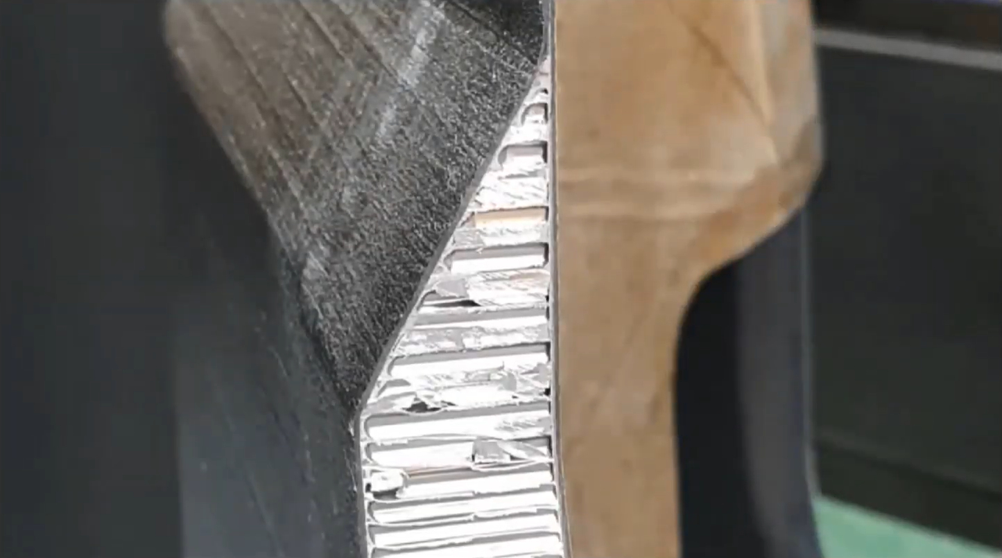
The IFS demonstrator used a CFRP-aluminum honeycomb sandwich construction. Photo Credit: Spirit AeroSystems Belfast presentation, final SuCoHS workshop.
Materials were evaluated for the new IFS design in SuCoHS. These evaluations concluded that Nomex honeycomb had to be eliminated due to poor thermal conductivity, which would have increased the amount of thermal blankets required. “So, we focused on aluminum honeycomb core with CFRP skins,” says Breen. However, this presents a risk for galvanic corrosion. Using glass fiber-reinforced polymer (GFRP) to insulate between these materials is a proven solution, but it creates a new problem in terms of potential for springback after cure. This is because the coefficient of thermal expansion (CTE) for CFRP is close to zero, but it is positive for GFRP, meaning there will be expansion during cure and contraction during cool down.
It was decided to produce a risk mitigation structure to demonstrate a processing solution to overcome this potential springback issue. The risk mitigation structure was made on the full-scale demonstrator tool but using a layup on a small portion of the tool. Thus, it wasn’t the full part but did reflect the full curvature. The team successfully achieved layup and autoclave cure of this part without springback.
The mold tool used for the IFS demonstrator had to withstand up 200°C and 6 bar during autoclave cure. A metal tool would have been too expensive for this one-off project. The team decided to use a CFRP tool, which Spirit Belfast has vast experience with. This also would result in a 300-kilogram tool versus the 2,450-kilogram alternative if CNC-machined tooling block material had been used. The CFRP tool could also be produced in-house, whereas the machined tooling block would have to be outsourced. Spirit Belfast produced a CFRP master, from which it laid up and cured an outer mold line (OML) CFRP mold tool for the IFS.
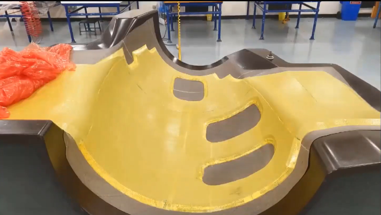
The yellow surface in the top image is film adhesive applied over aluminum honeycomb core. The final skin for the IFS demo was placed on top of this using AFP (center photo). After AFP, the IFS demo was autoclave cured, trimmed and inspected. Photo Credit: Spirit AeroSystems Belfast presentation, final SuCoHS workshop.
Fabrication of the final demonstrator began at Belfast, using hand layup for the outer skin, followed by film adhesive, aluminum honeycomb core and another layer of film adhesive. “You’ll see ramps at the edges of this yellow layer,” says Breen. “These enable the AFP head to roll smoothly up onto the honeycomb core and prevents core crushing during AFP and autoclave cure.”
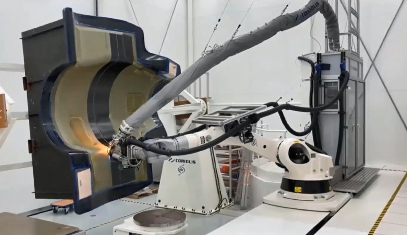
This partial layup was then sent to NLR for AFP layup of the inner skin. Note that NLR had first completed parameter optimization trials on flat panels. There were many challenges for this AFP process: laying onto the honeycomb plus the 3D geometry plus the ramps on the faceskin in the access panel areas and prepreg tape had to be laid at multiple orientations (e.g., 0°, ±45°, 90°). So, NLR had to evaluate the optimum material width versus deposition rate to handle all of these complexities. The part from Belfast was placed into a rotational positioning fixture at NLR, which would help during the AFP of the complex 3D skin, and the layup was successfully completed using NLR’s Coriolis Composites (Quéven, France) C1 AFP machine.
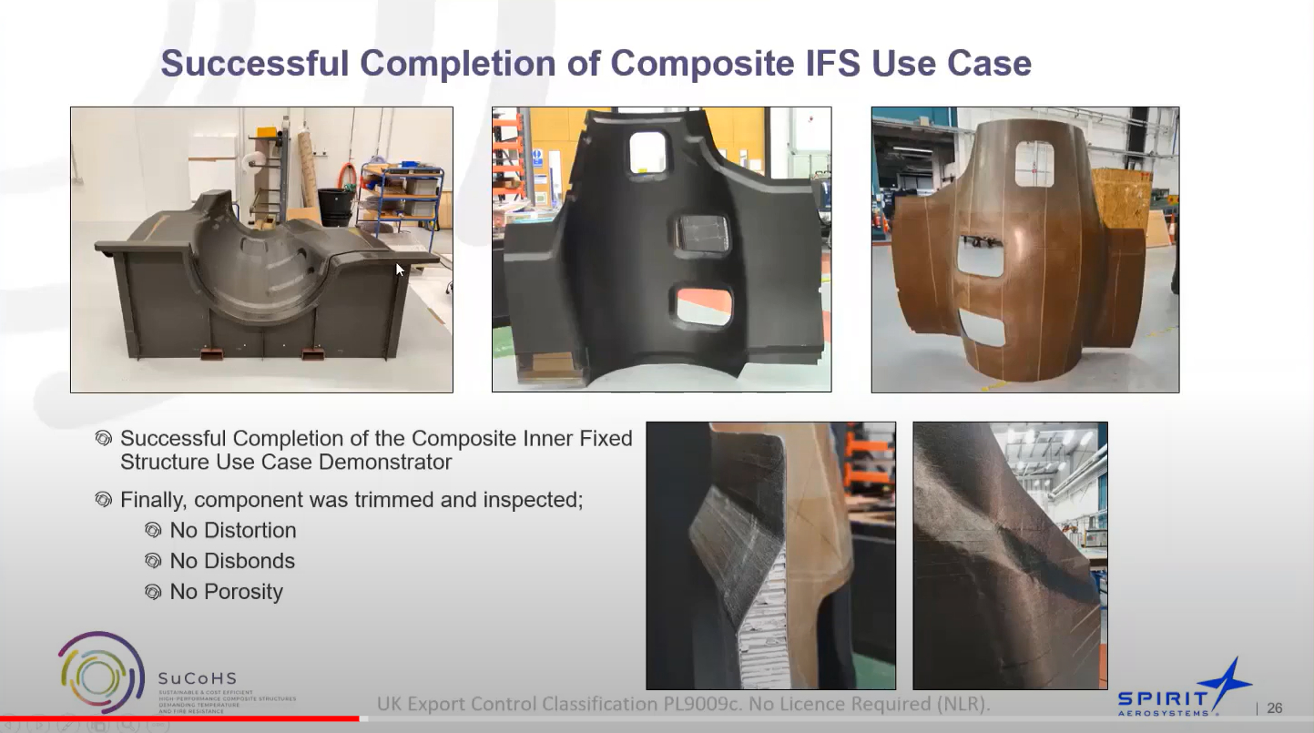
After AFP, the part was cured in one of the production autoclaves at GKN Fokker down the road because NLR didn’t have an autoclave large enough. “We used Synthesites sensors and its Optimold and Cure Simulator systems to successfully monitor cure during the autoclave cycle,” says Gerrits. “We achieved successful completion of the IFS demonstrator with no distortion, disbond, core crush or porosity.”
“For the inner nacelle parts, CE or PFA could be applied,” says Wille. “The team also had BMI as a reference material. One of the issues to be considered is the required tackiness level for AFP.” This is exacerbated by the complex shape of this demonstrator, which is quite narrow, he explains. “So the AFP machine cannot be too large in order to fit inside the geometry. The feasibility to use fiber placement was one of the key outcomes and different material options are still being considered.”
Aernnova tail cone demonstrator
Top photo shows tail cone demonstrator specifications while the manufacturing steps are shown at bottom, from top left clockwise: AFP of skin with fiber optic sensors, U-preforms placed on skin, layup with cauls on blade stiffeners and then vacuum bagged and ready for autoclave cure. Photo Credit: Aernnova and NLR presentations, final SuCoHS workshop.
This demonstrator was a five stringer-stiffened skin panel representative of the rear fuselage tail cone, and was made using the toughened CE thin-ply prepreg. One of the key issues for the tail cone demonstrator is that this section of the airframe must meet fire testing requirements because it houses the auxiliary power unit (APU) which burns jet fuel to generate electrical power for the aircraft when not in flight. FHNW did initial trials using its PES-toughened cyanate ester resin system via hand layup panels made with NTPT’s thin-ply prepreg. The panels were cured at 180°C.
After these initial trials, work began to fabricate the 5-stringer panel demonstrator. AFP was used to layup the skin including (as described above) optical fibers with FBG sensors. The stringers were formed by creating 125-millimeter-wide U-shaped preforms which were then abutted, with an extra laminate placed in between, to reach the required thickness and form the five blade stiffeners. NLR created these preforms using its automated hot drape forming system (see images and video below). As shown at right, the skin-stringer layup was vacuum bagged, cauls were placed on top and the panel was autoclave cured. The cure was monitored using the PhotonFirst FBG sensors as well as the dielectric sensors from Synthesites.
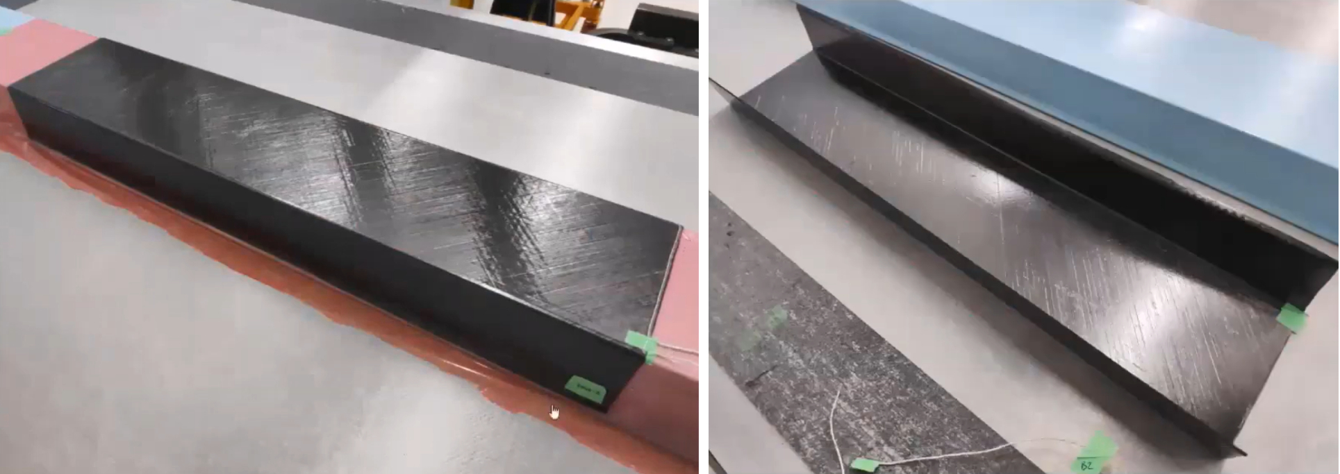
AFP prepreg on preform mandrel/tool (left) and hot drape formed stringer preform (right) to be placed on AFP skin for final demonstrator. Photo Credit: Aernnova and NLR presentations, final SuCoHS workshop.
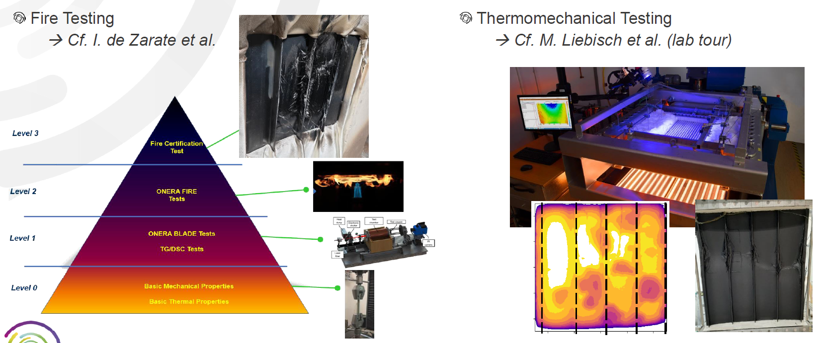
Fire and thermomechanical testing in SuCoHS project. Photo Credit: Aernnova presentation, SuCoHS final workshop.
The tail cone stringer-panel demonstrator was successfully produced and then used to perform fire testing and subsequent load testing to validate thermomechanical models and simulation. There was a significant amount of work done here. For more details watch the SuCoHS final workshop presentation by Martin Liebisch at DLR and Juan Penche at Aernnova.
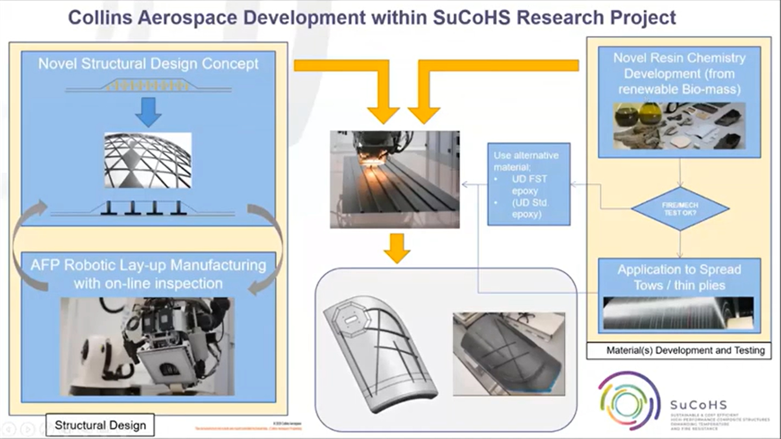
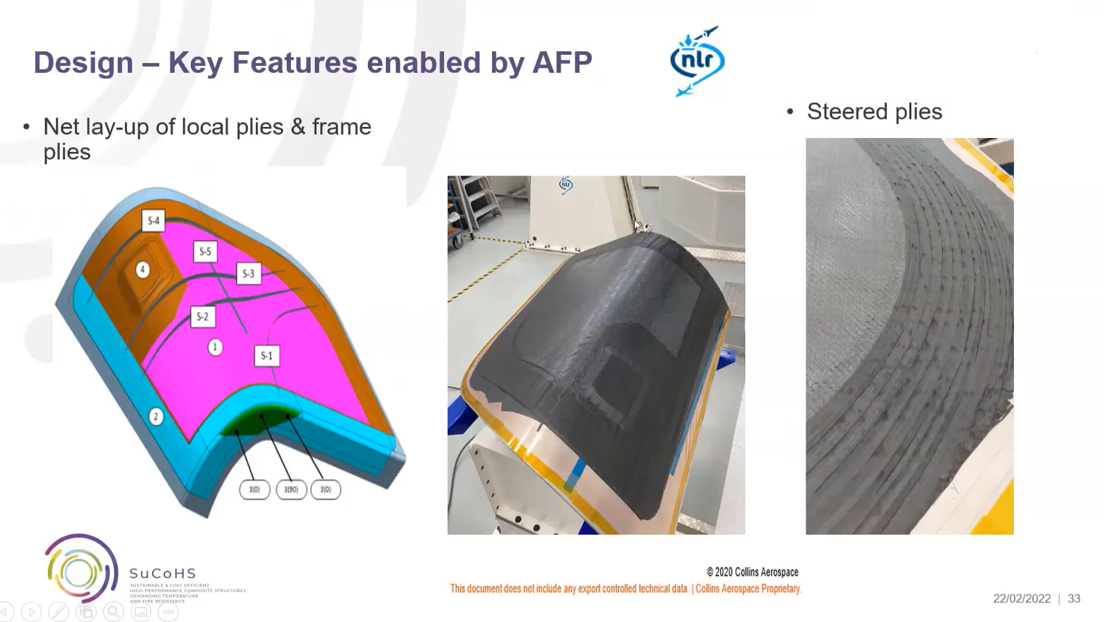
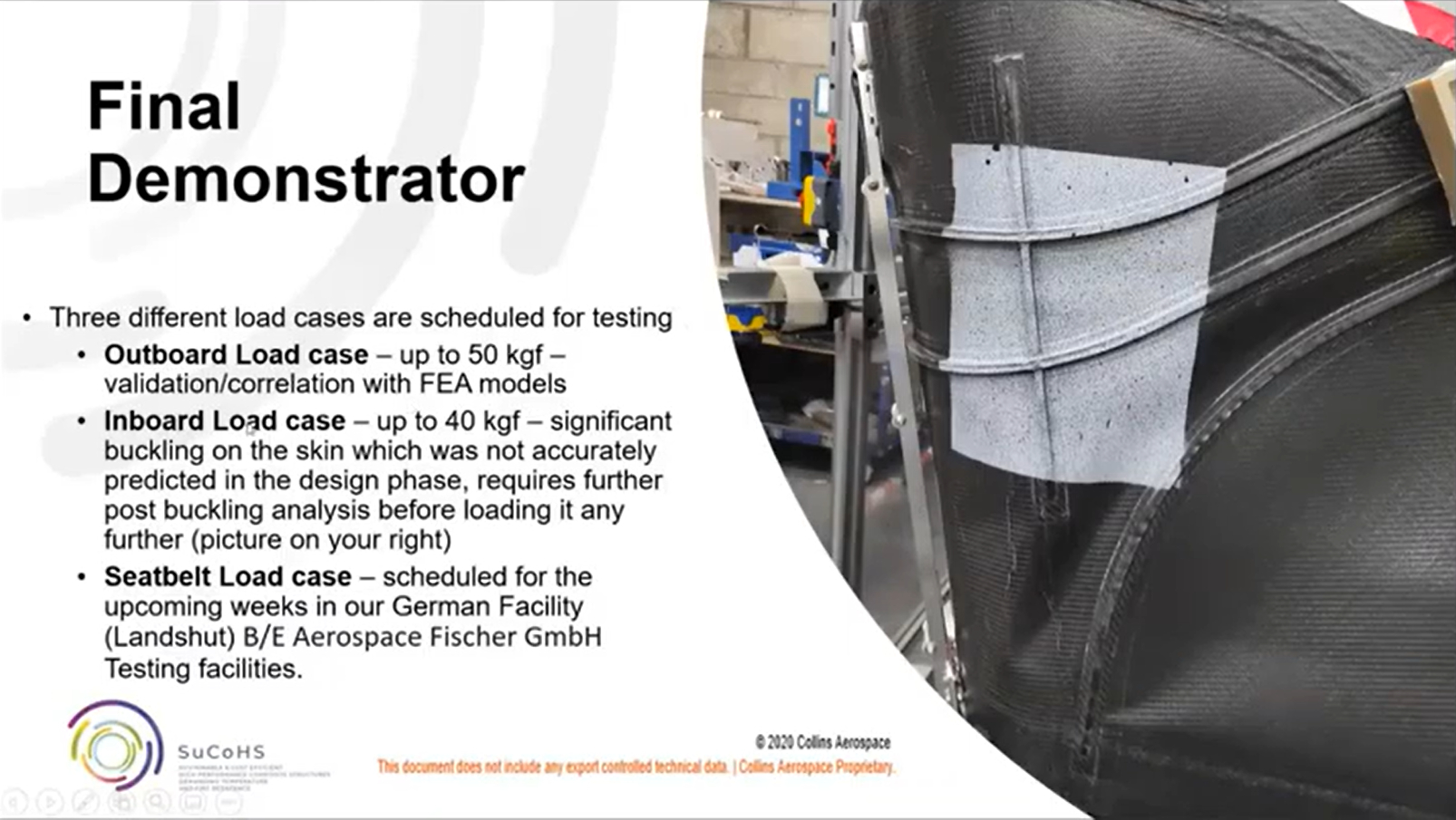
Collins Aerospace seat shell demonstrator
As explained by Paolo Ballocchi, senior manager, research, composite structures at Collins Aerospace, one goal of the seat shell demonstrator within SuCoHS was robotic layup of seat structures. The demonstrator was based on a new family of business class seats where the shell structure is not just a shroud but instead provides a load path between the occupant seat belt to the floor connection in a crash situation. Other goals were to develop a novel design and use of biomaterials, noting that all such interiors structures must meet fire, smoke and toxicity (FST) requirements as specified in FAR 25.853.
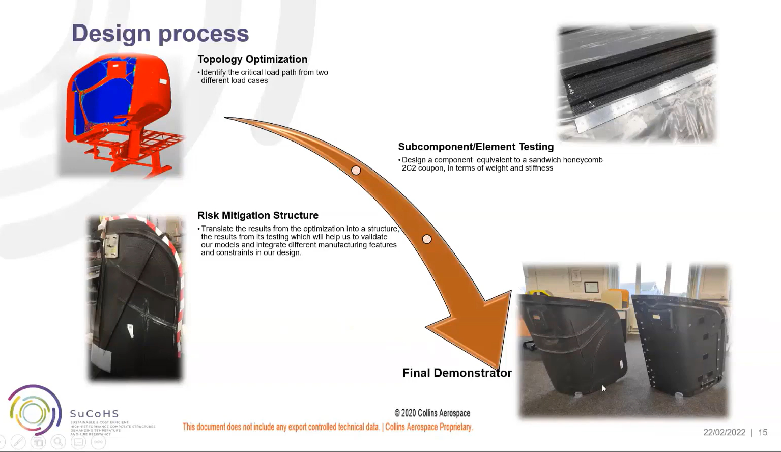
Design process for new composite seat use case demonstrator. Photo Credit: Collins Aerospace presentation, final SuCoHS workshop.
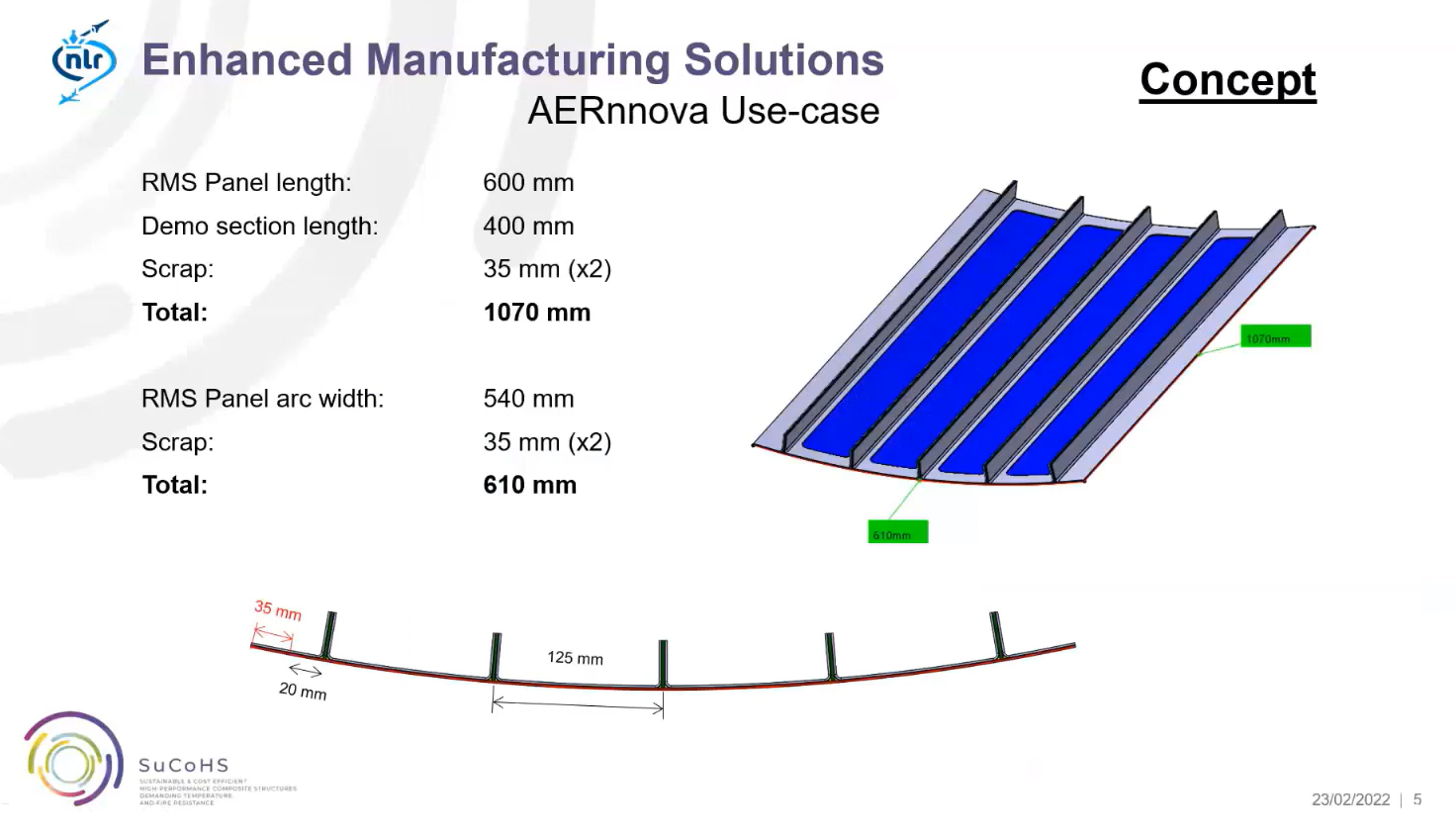
Typical construction of a business class seat shell has been a sandwich construction of CFRP skins with Nomex honeycomb core. But this does not facilitate high-rate production. The baseline material for this demonstrator was 2x2 carbon fiber twill woven fabric with an FST epoxy. Ballocchi explained that the goal in SuCoHS was to develop a new structural concept to replace the CFRP and honeycomb sandwich (see bottom right of image at right). The new design used CFRP ribs to reinforce a thin, load-carrying skin. “We identified the critical load path for this design using topology optimization,” says Ballocchi. This is still a work in progress to validate and optimize this new design with regard to modelling structural behavior and predicting failure.
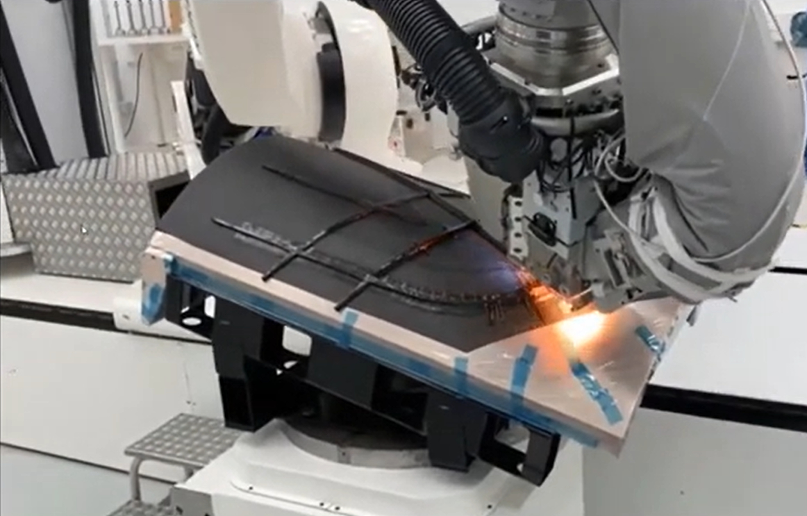
The novel design’s use of AFP and UD tape materials would reduce both material used and waste. Steered AFP was key to enabling a near net shape layup as well as material reduction of two-thirds. It also only required prepreg, eliminating honeycomb, film adhesive layers and potting compound typically required for sandwich construction. AFP also reduced manual labor hours by 50%.
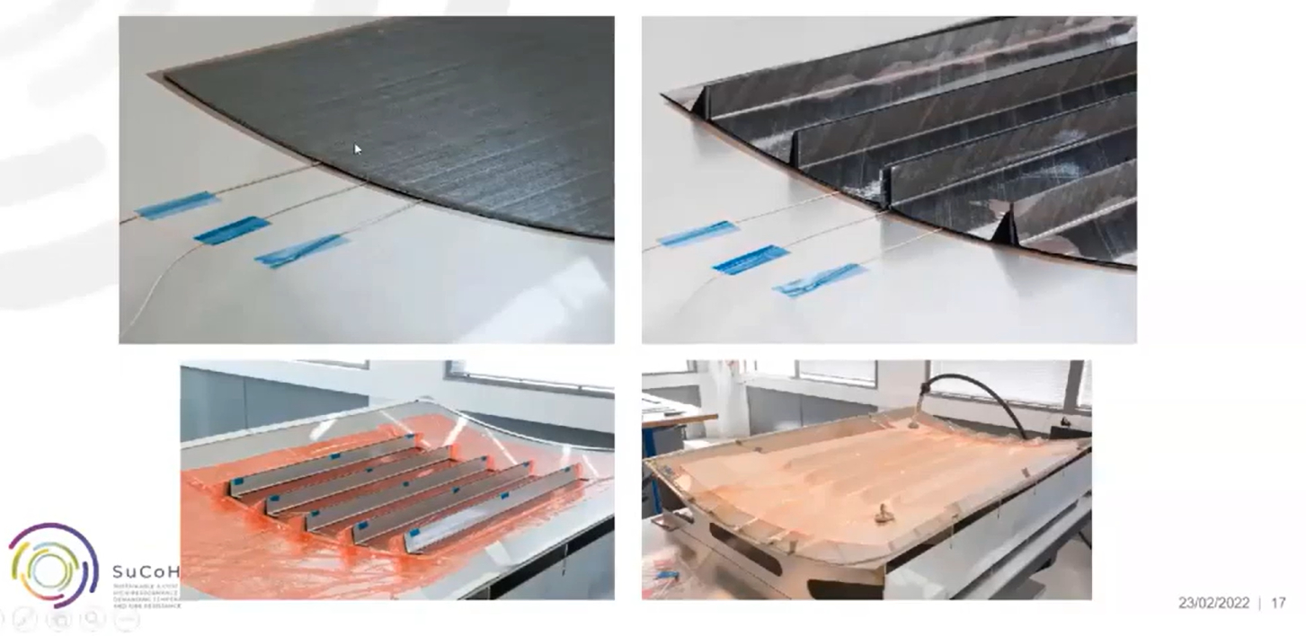
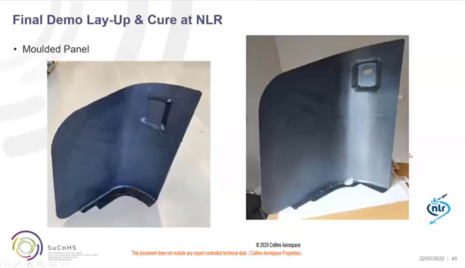
The final demonstrator was made using a carbon fiber-reinforced PFA UD tape made by TFC. Layup of the final demonstrator was completed at NLR. The skin was laid first, followed by an orthotropic stiffener grid. A reinforced molded silicone vacuum bag was fabricated to accurately mold the stiffeners during autoclave cure. The slideshow below gives highlights of the demonstrator fabrication and subsequent testing.
Collins Aerospace seat demonstrator
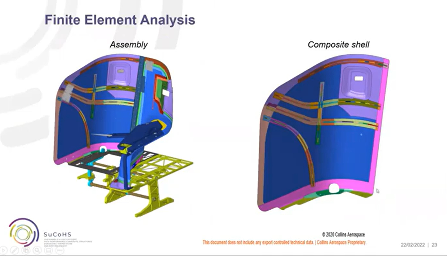
Photo Credit for all slideshow images: Collins Aerospace presentation, final SuCoHS workshop.
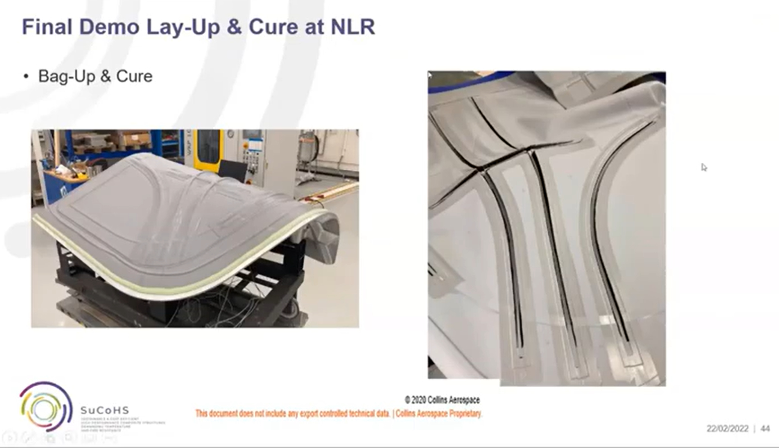
A reusable vacuum bag helped to ensure consolidation of the grid stiffeners.
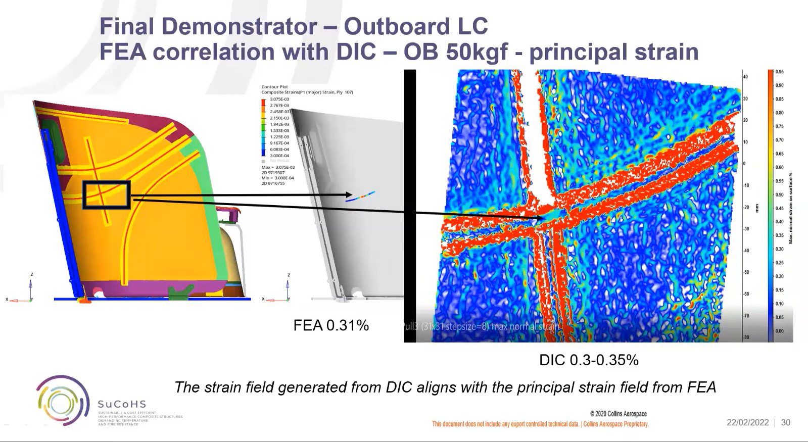
Digital image correlation was used to validate prinicipal strains in FEA. Photo Credit: Collins Aerospace presentation, final SuCoHS workshop.
SuCoHS achievements and next phase
SuCoHS is such a vast project, with so many different types of work completed. I asked Wille and Gerrits what they see as the biggest achievement? “To me it was bringing together such a strong consortium, comprising a group of people with many different kinds of expertise on many levels. And by such a good collaboration, we were able to find solutions together. We had universities, material suppliers and end-users, R&D engineers and engineering companies, as well as sensor partners that were also able to implement sensors inside the materials that we were developing. And that is also quite new — to achieve this implementation of sensors so that we can have visibility into the processes to improve them and also continuous monitoring during production. In addition, after the structure is in use, there is the ability to detect impact events, as well as their location, size and potential damage.” He also notes additional work, including fire and thermomechanical analysis, testing and exploration of how these results can be used in future structures certification.
“I agree that it was a well-balanced project, with excellent project partners,” says Wille. “The material suppliers were pushing new ideas and wanted to do manufacturing trials, and the end-users were pulling through, asking if project partners could look at their designs. So, there was complexity of designs, materials and processes, and how to manufacture. And there was a lot of discussion in different directions, asking for new ideas and for new technologies to achieve real improvements. And because all of the partners were open and cooperating like this, we were not only able to develop new materials and processing options but manufacture final end use structures that have been undergoing fire, thermal and mechanical testing.”
He adds, “You can always find demonstrators, but most of the time, they are simply to prove manufacturability or to show a certain design and are difficult to use for mechanical tests. This is also something about SuCoHS and was one of the best achievements to have throughout — development through all scales from fundamental research up to final demonstration structures that were then tested.”
Will there be a follow-on project when SuCoHS ends? “Our aim is to continue,” says Wille. “There are quite a few ideas, especially looking into sustainability and how to continue with those solutions and further improve them. But we will have to apply for new project funding.” Gerrits agrees that the circular economy is one of the topics of high interest: “LCA [life cycle analysis] for different designs, and investigating bio-based solutions is helpful, as well as the implementation of sensors to give information about possible maintenance or repair. So, everything that's related to a circular economy is already quite involved in this program, and thus, we are quite well prepared for the next step to look for more sustainable solutions. And we're looking for possibilities to go further.”
This project has received funding from the European Union’s Horizon 2020 research and innovation programme under grant agreement No 769178. For more information about the SuCoHS project, contact Tobias Wille (tobias.wille@dlr.de) or Wilco Gerrits (Wilco.Gerrits@nlr.nl).


Related Content

Materials & Processes: Fibers for composites
The structural properties of composite materials are derived primarily from the fiber reinforcement. Fiber types, their manufacture, their uses and the end-market applications in which they find most use are described.
Read More
Materials & Processes: Resin matrices for composites
The matrix binds the fiber reinforcement, gives the composite component its shape and determines its surface quality. A composite matrix may be a polymer, ceramic, metal or carbon. Here’s a guide to selection.
Read More
Cryo-compressed hydrogen, the best solution for storage and refueling stations?
Cryomotive’s CRYOGAS solution claims the highest storage density, lowest refueling cost and widest operating range without H2 losses while using one-fifth the carbon fiber required in compressed gas tanks.
Read More
PEEK vs. PEKK vs. PAEK and continuous compression molding
Suppliers of thermoplastics and carbon fiber chime in regarding PEEK vs. PEKK, and now PAEK, as well as in-situ consolidation — the supply chain for thermoplastic tape composites continues to evolve.
Read MoreRead Next

From the CW Archives: The tale of the thermoplastic cryotank
In 2006, guest columnist Bob Hartunian related the story of his efforts two decades prior, while at McDonnell Douglas, to develop a thermoplastic composite crytank for hydrogen storage. He learned a lot of lessons.
Read More
CW’s 2024 Top Shops survey offers new approach to benchmarking
Respondents that complete the survey by April 30, 2024, have the chance to be recognized as an honoree.
Read More
Composites end markets: Energy (2024)
Composites are used widely in oil/gas, wind and other renewable energy applications. Despite market challenges, growth potential and innovation for composites continue.
Read More