
Optimized approach to predict delamination failure in CFRTP structures
ARRK Engineering and Mitsui Chemicals improved delamination prediction accuracy to help optimize absorbed energy/failure load for an overmolded TAFNEX CF/PP UD tape bumper beam.


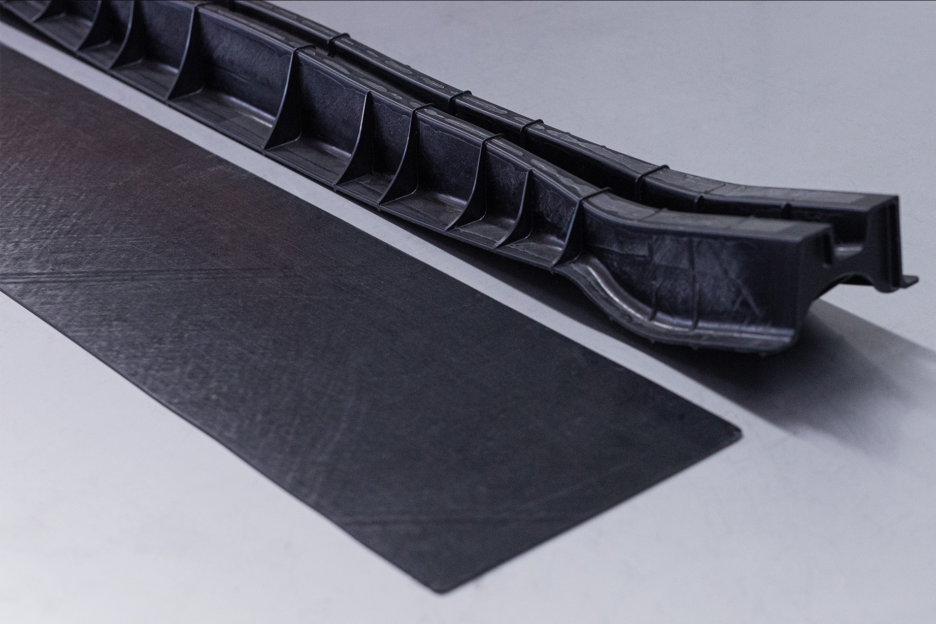
Figure 1. Front bumper beam and TAFNEX CF-PP UD sheet. ARRK Engineering optimized a CFRTP front bumper beam made using KraussMaffei’s FiberForm process and composite sheet made of TAFNEX carbon fiber/polypropylene (CF/PP) unidirectional (UD) tape overmolded with long glass fiber-reinforced PP (EDX4030), both materials from Mitsui Chemicals. Photo Credit, all images: ARRK Engineering, Mitsui Chemicals
The use of carbon fiber-reinforced thermoplastic (CFRTP) composites is growing as mobility companies seek high-performance parts with reduced weight to reduce energy consumption. One such material is TAFNEX carbon fiber-reinforced polypropylene (CF/PP) unidirectional (UD) tape, developed by Mitsui Chemicals (Tokyo, Japan). TAFNEX features a new PP formulation plus special fiber interface technology, enabling fully impregnated tapes that can reduce weight versus metals and plastics, and also offer excellent processability, low moisture absorption and short cycle times. TAFNEX also improves sustainability via low process temperatures, good recycling properties and a high potential for structural components with a lower carbon footprint.
ARRK Engineering (Munich, Germany) worked with Mitsui Chemicals to investigate simulation methods using an automotive bumper beam made with TAFNEX. A key issue for such safety-relevant components is the accurate prediction of delamination in the composite materials. This analysis is necessary because delamination may significantly reduce strength and provide an early failure mode. However, predicting delamination isn’t possible with standard finite element modeling (FEM) because it is based on modeling the structures as shells, or surfaces, without thickness.


ARRK Engineering used a combination of simulation and physical validation tests to optimize a CFRTP bumper beam, enabling accurate prediction of delamination while minimizing runtime, development time and cost.
Stacked shell modeling is an approach used to predict delamination very precisely. Typically, every ply in a composite laminate is modeled as a shell in the stack. However, the resulting large number of stacked surfaces requires excessive runtime and high calculation costs. Thus, its application has been limited and it isn’t affordable to use for full vehicle simulations.
In order to correctly evaluate delamination of composites while retaining a good runtime performance of the simulation, ARRK Engineering developed reduced stacked shell modeling using LS-DYNA software from Ansys (Canonsburg, Pa., U.S.). This approach was used to predict delamination in the TAFNEX bumper beam and perform a full vehicle crash simulation. The front bumper beam was made using the FiberForm process from KraussMaffei (Munich, Germany), where a TAFNEX CF/PP UD sheet — produced by Van Wees UD and Crossply Technology (Tilburg, Netherlands) — was thermoformed and then overmolded with Mitsui Chemicals’ 30% long glass fiber-reinforced PP (EDX4030).
Reduced stacked shell modeling
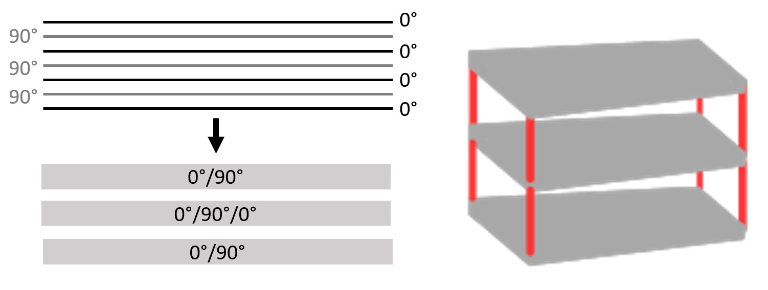
Figure 2. Reduced stacked shell modeling. This approach distributed the CFRTP composite laminate plies onto three layers in a symmetric fashion. The connection between layers was realized using cohesive elements in one model and beam elements as an alternative model with in-plane and out-of-plane elements sharing nodes.
ARRK Engineering set up a conventional single shell simulation model and a stacked shell model. The number of stacked shell layers was optimized to limit the amount of elements and contact surfaces yet have the possibility for delamination on both sides of the laminate mid-plane. Optimal results were found when using three layers, as results largely converged at this point; additional layers produced similar results but with a higher calculation cost.
Thus, for this reduced stacked shell approach, plies were distributed onto three layers in a symmetric fashion (Fig. 2). Additionally, the connection between layers was realized using cohesive elements (e.g., used to model adhesive joints) in one model and beam elements as an alternative. The motivation for this alternative modeling was to further reduce runtime while enabling the use of more sophisticated material models.
Material card creation and validation
Virtual material models were created in LS-DYNA based on extensive testing performed at ARRK Engineering, including tension, compression, shear, bending, interlaminar shear, double-cantilever beam and end-notched flexure. Two separate material models were prepared for in-plane and out-of-plane properties of the TAFNEX sheet, while a micromechanics approach was used for the EDX4030 long glass fiber overmolding compound using MAT_215 in LS-DYNA.
Material cards were validated using quasi-static and dynamic bending tests of the bumper beam with a cylindrical impactor.
To validate these material models, physical tests and simulations were completed in the form of quasi-static and dynamic bending of the front bumper beam with a cylindrical impactor, comparable to a center pole crash load case.
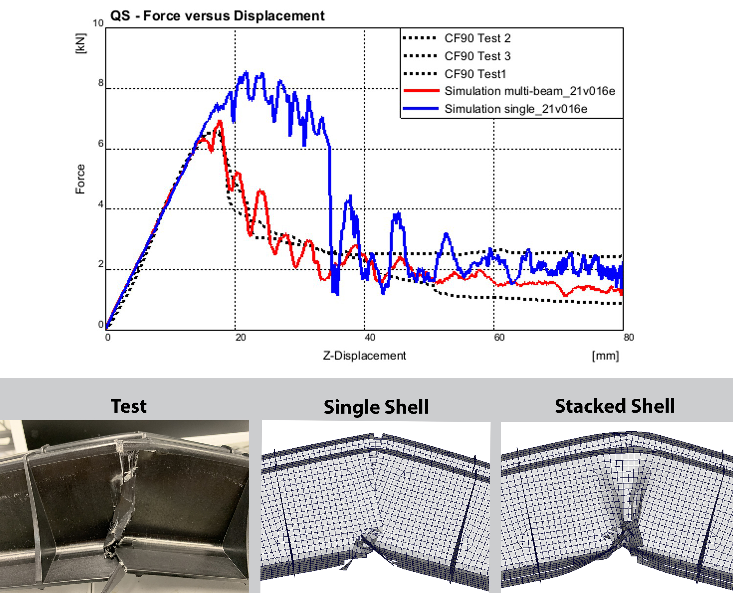
Figure 3. Comparison of force-displacement curves and failure behavior between test and simulation. Force-displacement curves for quasi-static bending of the CF90 bumper beam shows that single shell modeling (blue) overpredicts the failure load compared to reduced stacked shell modeling (red). Physical tests show failure of the beam sidewalls is dominated by delamination (left). While the reduced stacked shell model with beams (right) shows a comparable level of delamination as in the test, single shell models (center) cannot physically separate in the out-of-plane direction.
A comparison of force-displacement curves and failure modes can be found in Fig. 3. The results showed that the single shell model overpredicted the failure load at a maximum ≈8.5 kilonewtons, while the reduced stacked shell model failed closer to 7 kilonewtons and displayed delamination in the bumper beam sidewalls. With a mesh size of 4 millimeters and using 20 CPU, the reduced stacked shell modeling runtime increased by 40% versus single shell modeling. However, this is lower than typical stacked shell modeling and it accurately predicted both failure mechanism and load.
Structural laminate optimization, full vehicle evaluation
A full vehicle simulation of the overmolded CFRTP bumper beam with optimized TAFNEX laminate showed a doubling in absorbed energy, reduced number of failed elements and significantly decreased beam intrusion into the vehicle during crash.
After completing validation, the front bumper beam was evaluated virtually in a full vehicle setup according to the FMVSS-US Part 581 regulation. This simulation showed that the beam had insufficient energy absorption, resulting in significant intrusion and damage to the vehicle’s radiator. Based on the energy target from the full vehicle simulation, ARRK performed a parametric study to clarify the correlation between laminate stiffness and absorbed energy. The results were used to develop an optimized stiffness target and a composite layup to achieve this. New front bumper beams were tested with this improved layup. Test results showed the bumper beam’s load level and stiffness were improved according to predictions.
The optimized layup beam was then re-evaluated in a full vehicle simulation. Contact force and absorbed energy were doubled with a reduced number of failed elements and significantly decreased beam intrusion into the vehicle.
Application and outlook
ARRK Engineering showed that reduced stacked shell modeling can be used to accurately predict delamination in a CFRTP component. This approach provides a robust prediction capability while retaining efficient runtime performance and enables full vehicle simulations that reduce development time and cost. While other studies by [1] and [2] also showed application of stacked shells to evaluate delamination in composites, this new approach by ARRK Engineering was focused on maintaining computational performance in order to be able to integrate this modeling in full vehicle simulations. This was achieved by calibrating the material to a mesh size of 4 millimeters and reduced integrated element formulation, while reducing the stack to three layers with multiple plies in each layer.
References:
1 Shi D., (2016) “A Robust Crash Simulation Model for Composite Structures.” (Doctoral dissertation) Michigan State University.
2 Labeas, G., Fotopoulos, K., (2015, October) “Interlaminar Stresses Calculation Using a Stacked-Shell Finite Element Modeling Approach.” International Journal of Applied Mechanics.
About the Author
Olaf Hartmann
Olaf Hartmann is group leader for Material Simulation and Consulting at ARRK Engineering (Munich, Germany). He is focused on bringing efficient and predictive modeling into series development in automotive and aerospace applications. During the last 10 years, he has conceived and led numerous projects connecting Japanese and German industry. Olaf Hartmann holds a M.Sc. in material science from Friedrich-Alexander-University Erlangen-Nürnberg.


Related Content

The making of carbon fiber
A look at the process by which precursor becomes carbon fiber through a careful (and mostly proprietary) manipulation of temperature and tension.
Read More
Materials & Processes: Resin matrices for composites
The matrix binds the fiber reinforcement, gives the composite component its shape and determines its surface quality. A composite matrix may be a polymer, ceramic, metal or carbon. Here’s a guide to selection.
Read More
Novel dry tape for liquid molded composites
MTorres seeks to enable next-gen aircraft and open new markets for composites with low-cost, high-permeability tapes and versatile, high-speed production lines.
Read More
Thermoplastic composites welding advances for more sustainable airframes
Multiple demonstrators help various welding technologies approach TRL 6 in the quest for lighter weight, lower cost.
Read MoreRead Next

A digital twin to validate SMC performance in suspension structures
High-fidelity, anisotropic behavior material card, integrated with process simulation, structural FEA and validated with CT and physical tests enables optimization proven in award-winning SMC suspension knuckle.
Read More
Using machine learning to accelerate composites processing simulation
A speed gain of 1,000 to 10,000 times greater than traditional FE models has been achieved using machine learning models, enabling near real-time simulation for large composite components.
Read More
From the CW Archives: The tale of the thermoplastic cryotank
In 2006, guest columnist Bob Hartunian related the story of his efforts two decades prior, while at McDonnell Douglas, to develop a thermoplastic composite crytank for hydrogen storage. He learned a lot of lessons.
Read More