
Composite engine valves?
HPC technical editor Sara Black reports progress on CFRP intake and exhaust valves for race car engines.

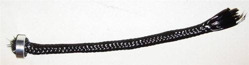
A closeup of the braided tube preform used to reinforce the valves. Note the retention bushing that keeps the fibers in place in the mold. Source: D. Radford, Colorado State University

The need for weight reduction and increased engine rpm in race cars like this one has motivated serious research into engine valves of carbon fiber-reinforced polymer composites. Source: SpeedTV / Photo: Doug Warner
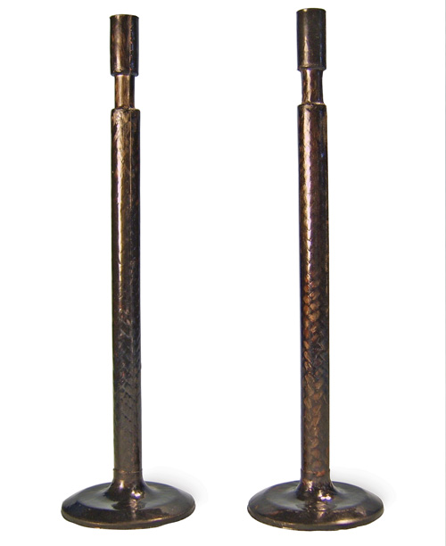
Valves molded using the CSU team’s carbon braid-reinforced, high-temperature polyimide resin. Soure: D. Radford, Colorado State University
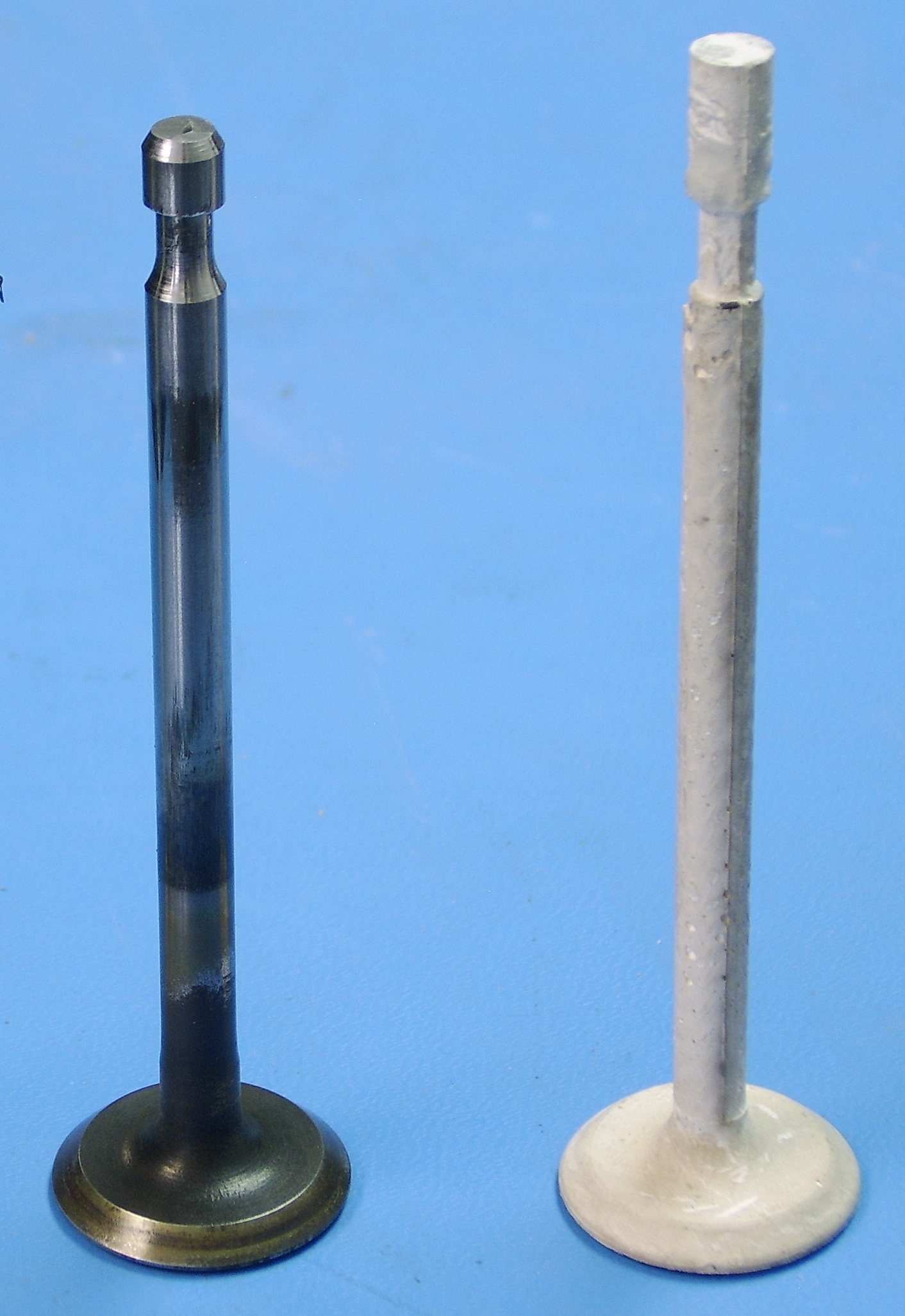
A side-by-side comparison of a steel valve and an inorganic matrix valve. Source: D. Radford, Colo. State University
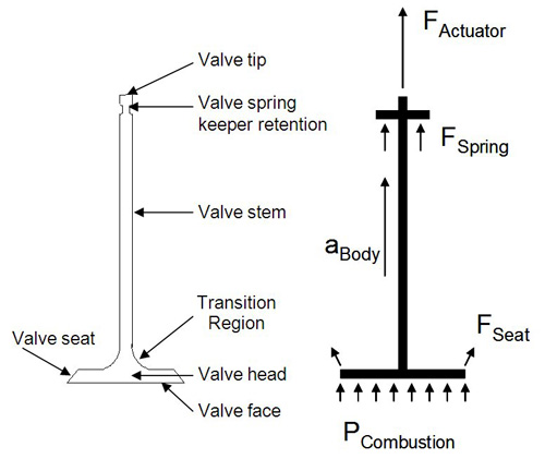
These diagrams illustrate the parts of an automotive engine valve (left) and the forces acting upon them (right). Source: D. Radford, Colorado State University
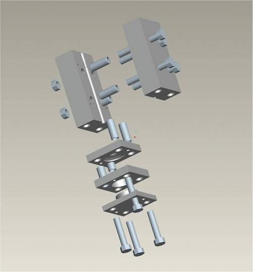
An artist’s rendering of the modular stainless steel mold used to create the valve parts. Source: D. Radford, Colorado State University


In auto racing, less mass means greater speed. Engineers have perpetually sought ways to reduce mass in race car components for better performance, and composites have been an enabling material in those efforts, particularly in race car body and frame components. At the Motorsport Engineering Research Center at Colorado State University (CSU, Ft. Collins, Colo.), however, mass-reduction research has focused on a composite solution in a very unlikely area: Investigators Donald Radford, Richard Buckley and a cadre of CSU engineering students are molding composite, one-piece engine valves that are a fraction of the weight of metallic versions.
Targeting engine valves not only reduces weight, but more importantly for racing purposes, also opens up the opportunity to increase practical engine speed. “The rpm [revolutions per minute] limit of most modern engines is governed by the speed at which the valve train becomes unstable,” explains Radford. “Since valve ‘jump’ and ‘bounce’ are governed by the mass and stiffness of the valve train components, decreasing valve mass should increase the operating speed of the engine.” The team has spent several years demonstrating the potential performance of resin transfer molded (RTM’d), fiber-reinforced, high-temperature matrix valves to replace materials currently in use.


Materials vs. harsh conditions
Steel is still the predominant material for mass-produced engine valves, and stainless steel is not uncommon because it provides better wear resistance and heat transfer than steel at nearly the same mass. In racing applications, titanium valves often are used because their mass is 60 percent of that of steel valves, but primarily for intake valves. “Typically, valves see temperatures of 400°C/752°F on the intake valve face and 900°C/1652°F on the exhaust valve face,” says Radford. Titanium cannot take the heat as an exhaust valve. Further, titanium does not have the high-cycle fatigue performance of steel and, therefore, requires hardening treatments, which increase process complexity and cost. Ceramic and ceramic-head valves have been demonstrated for use as exhaust valves, at only 40 percent the mass of steel valves, but the brittle failure mode of ceramic versions can have devastating consequences on the engine. Formula 1 racing teams have used titanium aluminide intermetallic valves, which weigh half as much as their steel counterparts. They are produced in a very complex manufacturing process that requires several materials, but today F1 teams typically employ titanium alloy valves. The CSU team’s goal is to mitigate all the negatives: Says Radford, “We want to reduce mass, increase stiffness, overcome brittle failure and simplify manufacture with a fiber-reinforced composite.”The concept of composite valves has been around for a while. In the early 1980s, Polimotor Research Inc. (Fairlawn, N.J.) attempted an entire carbon-reinforced polymer engine concept, based on a Ford engine, which used high-temperature carbon-reinforced polyamide-imide (PAI) for valve stems and ceramic for valve heads. The inline, 4-cylinder engine weighed only 168 lb/76 kg, notes Radford. In the 1980s, NASA’s Langley Research Center (Virginia) undertook a carbon/carbon engine project in which carbon composite valves were produced and tested. These previous efforts used multipart concepts to address the varying temperatures seen throughout the valve, and the bonded joint between the valve head and valve stem was often a point of structural failure. Radford’s team believes the potential is there for lightweight valves made in one piece, scalable to production volumes, although considerable design and manufacturing challenges remain.
One-piece preform, high-temperature resin
The valves Radford and his team designed have the same size and shape as conventional internal combustion engine valves. Total length is about 100 mm/4 inches, and weight, in steel, is approximately 38g. Finite element analysis (FEA) modeling showed that very little carbon fiber was required along the length of a composite valve stem — two 12K tows were sufficient when strength alone was considered. But, significantly greater reinforcement was indicated in the transition region, at the intersection of the stem and the head, where peak stress occurred, and in the valve head itself, due to the bending loads imposed by the valve seat area.The selected composite design comprised a two-layer braided carbon fiber tube 6.4 mm/0.25 inch in diameter that incorporates 60 percent axial unidirectional tow for additional axial bending resistance. Two small discs of plain-weave fabric were added to the valve face (more on these below) to resist the imposed bending loads. The matrix is a high-temperature PETI-RFI polyimide resin from Langley Research Center.
The PETI-RFI resin behaves as a thermoplastic below 280°C/536°F, but crosslinks and converts to a thermoset resin above the cure temperature of 300°C/572°F. Because of this unique characteristic, Radford’s team devised a plan to inject the resin into the mold at elevated temperature, but below the cure temperature. Once injection was complete, the mold was removed from the injection machine, unvented mold caps were fixed in the port and vents, and the mold was placed in an oven for complete cure and crosslinking.
Because the valve was to be made in one piece, the team initially designed and prototyped a single-cavity aluminum mold. But problems arose: nonuniform filling, difficulty with preform retention and fiber wash as well as part lock in the mold. Worse, the aluminum mold distorted over time due to the high cure temperatures, which led to sealing problems and ultimately void formation in parts. Ultimately, a modular, multipiece, split-cavity stainless steel mold was developed to improve filling and wetout, provide for greater clamp pressures and permit easier part removal, reports Radford.
One of the more significant challenges was how to maintain the tiny braid in the correct position within the mold during injection. The ultimate solution was a two-piece preform retention bushing that clamps the braided sleeve at the valve tip end. The bushing keeps the fibers from washing down the mold and acts to “open” the braid to force resin inside, so that preform wetout, according to Radford, occurs from the inside out.
Another challenge was how to add local fiber reinforcement at the valve face. The initial thought was to “spiral” the end of the braid over the flat face, but placement was uncertain because of resin flow during injection. The answer was to “prepreg” dry carbon plain-weave fabric by melting the PETI-RFI, in its thermoplastic state, onto the fabric. Small discs, the same diameter as the valve face, were then cut or punched from the resin-impregnated fabric to form the discs mentioned above. The discs were easily pressed into the face of the valve mold during mold assembly and provided the needed extra fiber volume in the head area, says Radford. “When the hot resin is injected into the mold, the resin in the discs melts together with it,” he explains. “We removed the injection end cap to confirm disc wetout before oven cure. It gives us flexibility to accomplish additive manufacture for local loads and could transition to adding functional features like heat transfer materials.”
Test results, future directions
Valves were successfully produced with the carbon preform and PETI-RFI resin in the modular steel mold. They weighed a mere 7.3g, only 19 percent of the stock steel valve (solid titanium would weigh 22g). Static tensile, motored dynamic and fired running engine tests were undertaken. The valves performed well in the static and motored dynamic tests, reports Radford. Tensile failure occurred in the valve spring keeper region due to shear, but at a load an order of magnitude greater than the valve load predicted for an actual engine. In the motored dynamic test, the valves were installed in a test engine connected to an electric motor, which operated the valves for more than 15 minutes in excess of 5,000 rpm with no damage.The real test came with installation of the valves in an actual Junior Dragster-style, side-valve, air-cooled race engine, with manual throttle control. Valves operated well at idle, but when they were taken to near full load, they failed within 10 minutes. Upon examination, erosion and material loss was observed on the valve face near the seat. It was apparent, and this observation was subsequently confirmed with thermocouple data, that the air-cooled racing engine had developed intake valve temperatures greater than 425°C/797°F — much higher than expected. “We achieved our goal of a one-piece composite valve that is structurally able to perform as an intake valve, but thermal performance of the composites material itself turns out to be the real challenge,” states Radford.
Since the initial experiments, the group has refined its work based on the lessons learned. For example, all of the initial valve articles had slight surface porosity, which may have affected thermal performance. Radford reports that vacuum degassing of the melt prior to injection as well as a well-sealed mold is now considered critical to avoid void formation. Other measures include trying to boost the polyimide’s thermal performance with nanoscale additives. New inorganic polymers also are being investigated, including “geopolymers” based on alumina silicate, like those offered by Pyromeral (Pont Sainte Maxence, France and Dallas, Texas). These handle like a two-part epoxy, can be processed by RTM and offer very high temperature performance (~750°C/1382°F), but toughness is a challenge, he notes. Valves made with the same reinforcements but infused with the ceramic matrix are white in color, rather than black.
Also under investigation as high-temperature matrix alternatives are various sol gels and colloidal silica particle suspensions. Additionally, the team is seeking ways to make its original carbon fiber/polyimide design more heat- and erosion-resistant. “We are looking at various thermal barriers, including spray-on coatings or metal facings on the valve face, but still need to address the coefficient of thermal expansion (CTE) issues there,” adds Radford.
Given the current economic downturn and resulting auto industry slowdown, OEMs preoccupied with reinventing themselves and designing “greener” vehicles that will define transportation’s future are unlikely to see composite valves as a priority. Yet, the research is promising. In auto racing, where speed still trumps green, composite valves — and (who knows?) even an all-composite engine — could be the next competitive breakthrough.


Related Content

Cycling forward with bike frame materials and processes
Fine-tuning of conventional materials and processes characterizes today’s CFRP bicycle frame manufacturing, whether in the large factories of Asia or at reshored facilities in North America and Europe. Thermoplastic resins and automated processes are on the horizon, though likely years away from high-volume production levels.
Read More
Carbon fiber in pressure vessels for hydrogen
The emerging H2 economy drives tank development for aircraft, ships and gas transport.
Read More
Manufacturing the MFFD thermoplastic composite fuselage
Demonstrator’s upper, lower shells and assembly prove materials and new processes for lighter, cheaper and more sustainable high-rate future aircraft.
Read More
TU Munich develops cuboidal conformable tanks using carbon fiber composites for increased hydrogen storage
Flat tank enabling standard platform for BEV and FCEV uses thermoplastic and thermoset composites, overwrapped skeleton design in pursuit of 25% more H2 storage.
Read MoreRead Next

Formula 1 team accelerates design-to-track speed
Race car builder automates manual chassis design phase with unique FEA-to-CAD utility.
Read More
Carbon fiber race car technology hits the streets
Porsche equips its new Carrera GT with the first-ever all-carbon chassis on a production automobile.
Read More
From the CW Archives: The tale of the thermoplastic cryotank
In 2006, guest columnist Bob Hartunian related the story of his efforts two decades prior, while at McDonnell Douglas, to develop a thermoplastic composite crytank for hydrogen storage. He learned a lot of lessons.
Read More