
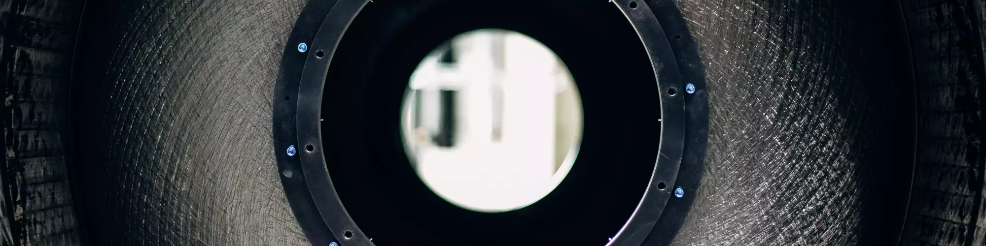


Thermoplastic composite upper stage LH2 tank
The PROCOMP project demonstrator tank uses in-situ consolidation during automated fiber placement (AFP) of carbon fiber/LMPAEK tape and ultrasonic welding for assembly. Photo Credit: DLR CC BY-NC-ND 3.0
The commercial space age has arrived and is growing rapidly, pursuing not only more satellites and space stations, but also asteroid mining, manufacturing in space and extraterrestrial settlements. Space vehicle launches totaled 72 in the first half of 2022, on pace to break 2021’s record of 135. They are projected to exceed 1,000 in 2040. This growth is thanks to SpaceX (Hawthorne, Calif., U.S.) slashing launch cost from an average of $18,500/kilogram between 1970 and 2000 to an average $2,500/kilogram for the Falcon 9 and a projected $1,500/kilogram for the Falcon 9 Heavy.
In addition to cutting cost, another key goal for launch vehicles is to increase payload. Carbon fiber-reinforced polymer (CFRP) fuel tanks can offer a weight reduction of 20-40% compared to traditional metal tanks. Multiple companies are developing such tanks, including Boeing (Arlington, Va., U.S.), which has demonstrated a technology readiness level (TRL) 6 for its all-composite cryogenic propulsion tank, passing pressure cycling tests and a maximum pressure test — reaching 3.75 times its design requirement — with no sign of failure.


Measuring 4.3 meters in diameter, this thermoset composite tank is roughly the same size as propellant tanks in the upper stage of NASA’s Space Launch System (SLS) rocket, aimed to land astronauts on the moon by 2025. Targeting the upper stage of such rockets is key, says Lars Brandt, project manager for space-related applications at the German Aerospace Center (DLR) for Lightweight Production Technology (ZLP, Augsburg, Germany), “because every kilogram you save in the upper stage tank is a kilogram of payload you can send into space. The lower stage, or rocket booster, falls back to Earth after launch but the upper stage completes the mission.”
In the 2019-2020 project PROCOMP, DLR set out to push “black” tanks, made using carbon fiber, even further. “Our idea was to use thermoplastic composites,” says Brandt, “due to their ductility in low-temperature environments, as well as other advantages such as in-situ consolidation during automated manufacture and welding for assembly without fasteners. This approach enables a new, two-piece design that allows you to access the inside of the tank for quality assurance and easier installation of equipment like filling sensors and propulsion management systems.” The latter comprise circumferential bulkheads to prevent sloshing of the liquid cryofuel and longitudinal vanes that guide that fuel to the nozzle for delivery to the rocket engine below. DLR proved this design by manufacturing a sub-scale demonstrator, using in-situ consolidation automated fiber placement (AFP) of low-melt polyaryletherketone (LMPAEK) prepreg tape with 100% inspection using a tape profile sensor and inline thermography.
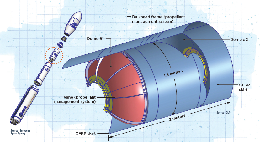
PROCOMP upper stage thermoplastic composite LH2 tank. Drawing illustrated by Susan Kraus.
Tank design
DLR has worked with cryogenic liquid hydrogen (LH2) storage for spacecraft since 2018. “In PROCOMP,” says Brandt, “we asked what would be needed to use a composite liquid hydrogen tank for the upper stage of the Ariane 6 launcher.” He notes that while SpaceX has decided to stay with metal tanks, the European Ariane 6 program will test a new upper stage with both liquid oxygen and LH2 tanks made from CFRP by 2025-26.
The PROCOMP team started with the volume of LH2 needed — approximately 5 tons — “and then we scaled it down to tooling we already had available,” says Brandt. The result was a 2-meter-long, 1.3-meter-diameter cylindrical tank with domed ends. “Next, we had to decide where to split the tank to develop the two-part design we wanted. We had a few different concepts but ended up with one of the two domes by itself, which would then be welded to an integrated part comprising the other dome co-consolidated to the main tank body plus skirts at both ends.” These skirts locate the tank within the multipiece launch vehicle and help to resist a variety of loads during launch, first-stage separation and subsequent flight.
“We had lots of design freedom in the beginning, but decided to use the existing tooling and a design where you have kind of a widening of the diameter in the integrated part,” explains Dominik Deden, ZLP research engineer in processes and automatization. “This allows the freestanding dome to fit inside the integrated part and then be welded after equipment installation. For us, this approach provided an optimal balance between performance, weight savings and manufacturability. The stand-alone dome is manufactured on the same tooling as the integrated part, which means that we do not have additional tooling costs.”
“However,” continues Deden, “this two-part design also required defining a ledge inside of the integrated part’s open skirt section for positioning the dome prior to welding. The weldline would not be very wide, so we needed to locate the dome precisely.” From this point, the team started computer aided design (CAD) using CATIA V5 software from Dassault Systèmes (Vélizy-Villacoublay, France) and Ansys (Canonsburg, Pa., U.S.) for finite element analysis (FEA).
As described in the SAMPE Europe 2020 paper, “Development of a lean production process for a thermoplastic composite upper stage propellant tank,” the laminate design for the tank was evaluated by modeling different static and buckling load cases considering a service temperature of 20 Kelvin (-253°C) and a pressure of 5 bar. The domes and main tank body would use 11 plies of unidirectional (UD) carbon fiber-reinforced (CF) LMPAEK tape, applied at 0° (longitudinal axis of the tank), ±30°, ±60°, ±45° and 90°, while the tank skirts would increase to 16 plies, with additional 0° and 90° plies to resist buckling. Consolidated thickness of each ply was 0.14 millimeter, giving a thickness of 1.54 millimeters in the domes and tank body, and 2.38 millimeters in the skirts due to a 210-millimeter overlap with the domes in the additional 0°/90° layers.
Automated layup and in-situ consolidation
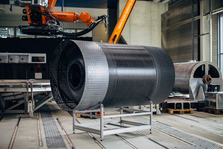
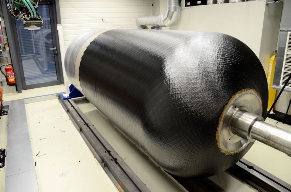
DLR used a robotic winding system and aluminum tool to manufacture the PROCOMP demonstrator tank (top) beginning with AFP in-situ consolidation of dome #1 (bottom). Photo Credit: DLR CC BY-NC-ND 3.0
After receiving the tank laminate design from the FEA/stress group, says Brandt, “we then had to check if it was possible to manufacture the tank using our AFP equipment.” The equipment used was a multiple tape-laying head (MTLH) from Advanced Fibre Placement Technology (AFPT, Dörth, Germany), a spin-off from Fraunhofer IPT (Aachen, Germany) that has specialized in laser-assisted tape winding (LATW) since 2007. The MTLH at DLR can apply up to three 0.5-inch-wide tapes and is mounted on a six-axis industrial robot capable of producing rotational parts up to 4 meters long and 3 meters in diameter.
“We did have to adjust the layup a little bit due to the limited reach of the AFP head,” says Brandt. “But these were minor modifications. We also tested using CF/LMPAEK tape as the first ply but decided instead to use an unreinforced LMPAEK film as the adhesion layer. We wanted to have a first ply that could be attached automatically in the future, but also needed adhesion in the dome regions to steer the tape during placement.”
After that, the first dome was placed and in-situ consolidated (see “Consolidating thermoplastic composite aerostructures in place”). It was then removed from the tooling (Fig. 1). “Next, we manufactured the second dome and the main part of the tank,” says Brandt. “Where those two scribe lines are shown on the second step in Figure 1 was where we slightly widened the diameter to have room to fit the first dome inside its skirt. We achieved this by adding an aluminum band to the tool before AFP layup of that skirt.”
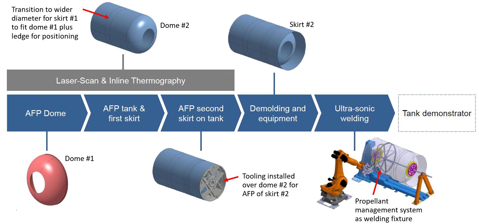
Fig. 1. Two-part, welded tank
Dome #1 was first AFP laid up/consolidated and demolded. The same tooling was then used to produce the integrated structure: dome #2, the tank body and both skirts. After demolding, the propellant management system (equipment in the diagram above) was installed and used as an anvil during welding of dome #1 and the integral part in a separate assembly fixture. Photo Credit: DLR CC BY-NC-ND 3.0
“That also helped us to create a sharp ledge to push the first dome against so that we would know it was positioned correctly for welding,” says Deden. “We then installed an additional tool over the second dome and used AFP to build the second skirt. We overplaced the tape directly onto the previously consolidated tank and part of the second dome.”
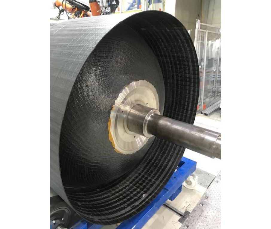
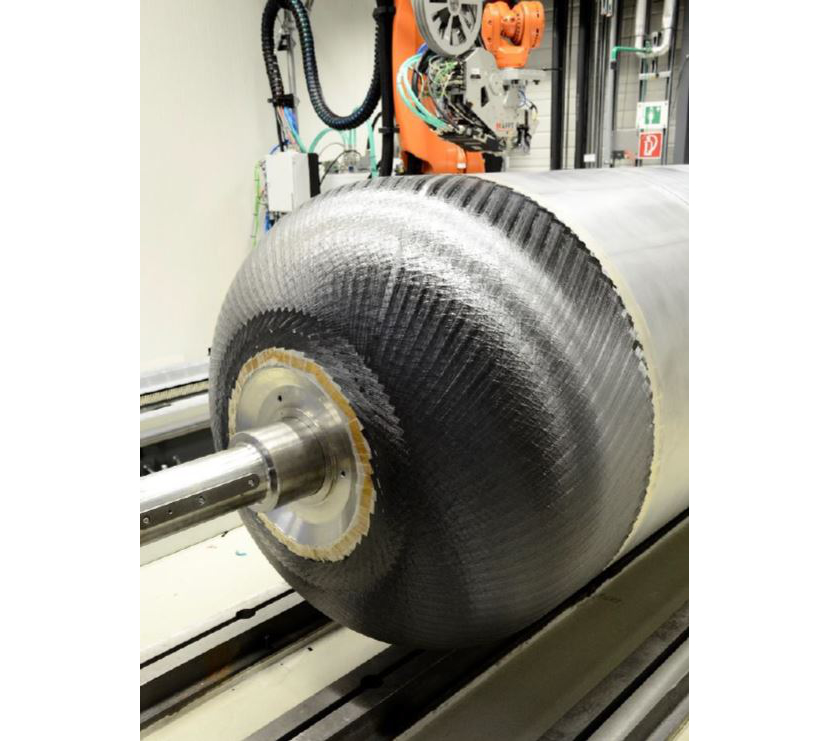
The PROCOMP demonstrator tank integral part during manufacture (top) and with skirt 2 AFP consolidated and overlapping dome 2 (bottom). Photo Credit: DLR CC BY-NC-ND 3.0
Brandt notes this is one advantage of in-situ consolidation with thermoplastic composites. “You can always add to the part with additional material,” he says. “So, the integral part comprised two complete skirts, the second dome and the body of the tank.”
Some have criticized in-situ consolidation AFP as a slow process that requires very high-quality tape to achieve a good laminate. “Those are fair points,” says Deden. “In our opinion, in-situ consolidation only makes sense if you are really exploiting its benefits. And you have to adapt your design to the in-situ process, which requires really understanding the details. It’s not effective if you just try to modify a design for an autoclave-consolidated thermoplastic part or for a normal AFP thermoset prepreg part.”
Welded assembly
After the integral tank part was removed from the tooling, the first dome and the completed integral part were joined in a welding fixture using continuous ultrasonic welding technology that DLR has developed. This part of the project was led by the team’s welding expert, Manuel Engelschall. “First, we outfitted the first dome with the propellant management system structures,” says Brandt. These included a circumferential profile at the bottom of the dome and a series of curved longitudinal vanes. “We made these from aluminum just to prove the assembly concept,” he explains. “For an actual tank, these could be composite and would be very similar to stringers and frames in an aircraft fuselage, so it’s well known how to produce these.”
The actual system parts weren’t a focus, but using the circumferential profile as an anvil for welding was. “We needed it to achieve the pressure to consolidate the thermoplastic composite weld,” says Brandt. “We also used an additional metal structure that was easy to insert and remove, just to make sure we had the stiffness required, because the tooling was no longer there to provide stability. We then welded a circumferential seam to join the dome and integral part.”
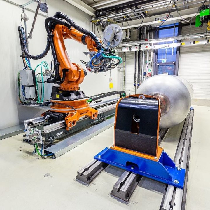
The welding system used in PROCOMP comprises a high-accuracy KUKA (Augsburg, Germany) robotic arm equipped with a sonotrode, having a spherical bearing surface of 25 millimeters in diameter. The sonotrode directs vibration orthogonally into the composite laminate. “We used the ultrasonic horn directly on the outer surface of the tank,” notes Brandt. “Heat was only generated at the welding contact area, due to friction. We inserted a 60-micron-thick layer of unreinforced LMPAEK as an energy director between the two surfaces being welded.”
Commonly employed in continuous ultrasonic welding, an energy director is used to focus the energy in the weld zone. The neat resin increases damping of the vibration from the ultrasonic waves compared to the reinforced weld surfaces, resulting in friction that melts the matrix in those surfaces. Welding speed was 20-25 millimeters/second and welding force was 400-600 newtons.
“In the beginning, we planned for a wider weld zone,” says Engelschall, “but after some calculations we were able to reduce it. For the demonstrator, we planned for two 15-millimeter-wide weld lines, but due to tooling issues we decided to go with only one line.”
100% inline inspection
Another key objective was quality assurance via automated systems developed by PROCOMP teammate Monika Mayer. “She combined a laserline with a special camera that automatically measures the height profiles of the tapes being placed. It is basically an advanced laser triangulation sensor,” explains Brandt. Similar systems have been developed by Profactor (Steyr, Austria), Danobat Composites (Elgoibar, Spain) and other partners in the ZAero project for zero-defect composites manufacturing (see “Improving composites processing with automated inspection, Part II”).
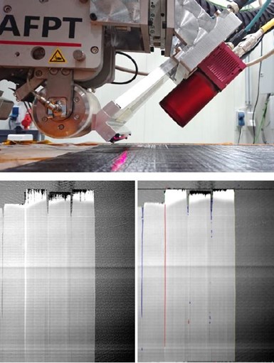
PROCOMP developed an inline inspection system using a laserline and special camera to detect gaps and overlaps during AFP in-situ consolidation. Photo Credit: DLR CC BY-NC-ND 3.0
“With this system,” Brandt continues, “we can measure gaps, overlaps and other defects consecutively, which means this is then taken into account for the next layer. This is important because gaps and overlaps in each layer can add up to a deviation in height that then affects the laminate and structure performance. So, we can detect these deviations in a very precise way, but we also have a full 3D surface after each layer. And it’s all done in-situ which means there’s no additional robot or time needed for these measurements.”
This data is necessary to show that the as-manufactured part conforms sufficiently to the CAD design and avoids significant knockdowns in strength due to defects. But what happens if there are gaps and overlaps detected during AFP? “During PROCOMP we simply demonstrated inspection, but there was no procedure to adjust the robotic path,” says Deden. “However, if you have gaps and overlaps in multiple layers, you could end up with a permanently wavy or buckled laminate, so it is important to find a solution for managing this with in-situ consolidated laminates.”
“The potential is there to adapt for when there are gaps and overlaps, but you have to be very careful,” says Brandt. “For example, for a tank it might make sense to do this to avoid leaks in the final structure. But if you adapt your robot path, you’re also adapting the fiber angle. So, you need to be able to analyze how the gap or overlap versus change in fiber angle will affect the final tank performance.”
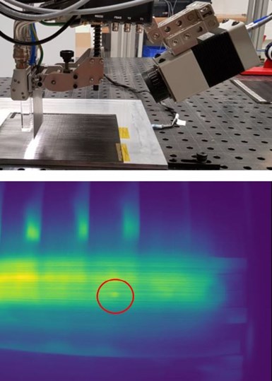
Inline thermography system to measure consolidation defects during AFP. Photo Credti: DLR CC BY-NC-ND 3.0
The second part of the inspection system was inline thermography using an infrared (IR) camera. “The concept here was to detect issues with consolidation during AFP,” says Brandt. “We placed the camera next to the compaction roller on the AFP head so that it could measure the temperature of the tapes after compression. Any air between the tape just laid and the underlying laminate would act as an insulator. We would then compare the cooldown rates in-situ to identify potential defects. We had promising results. For example, my colleagues simulated errors with Kapton polyimide foil, and these were easy to see. They then developed an algorithm that could track pixels on the IR camera and then export the temperature gradients so they could then look and say if it is in the range of the normal laminate behavior or if there was a problem.”
All of the inspection data is stored along with data from the controllers of the AFP head, the robot and the heating source using an integrated data management system. Brandt notes this is available as opensource software. All collected data was automatically annotated with context metadata to allow easy selection of regions of interest using time of capture, AFP layer and course number as well as spatial location on the part. A dashboard was also developed to provide real-time process monitoring and identification of emerging problems through trend analysis, including the ability to estimate part quality and analyze process data correlations.
Future development, LH2 aircraft?
The PROCOMP team considered the project and completed demonstrator a success. “We showed that our manufacturing process is very reliable, starting from calculating the loads to designing the tank, programming the AFP, welding of both parts and integration of a propulsion management system inside the tank. So, we achieved a lot, but we are already working in another project on the subjects that we couldn’t solve within PROCOMP.”
Another interesting aspect is that during this project, the large wave of German funding for H2 storage in aircraft started, says Brandt. “Now, we’ve seen that interests have just exploded.” Boeing is looking to advance its thermoset composite cryotank into applications for LH2 storage in zero-emissions aircraft, while Airbus has announced its first such aircraft will enter service by 2035 with multiple development centers aiming for ground and flight testing of LH2 tanks in 2023 and 2026, respectively.
“I think we demonstrated key benefits that could be useful even for LH2 tanks in aircraft,” says Brandt. “They will most likely not be integrated into aircraft wings, at least in the first versions with a classical design, and thus will be extra structures that must be as light as possible. It may be a bit unintuitive to use CFRP in such tanks, but I believe it’s the only solution we have in the long run, and thermoplastic composites may indeed play a key part.”


.jpg;maxWidth=300;quality=90;format=webp)

Related Content

Thermoset-thermoplastic joining, natural fibers enable sustainability-focused brake cover
Award-winning motorcycle brake disc cover showcases potential for KTM Technologies’ Conexus joining technology and flax fiber composites.
Read More
3D-printed CFRP tools for serial production of composite landing flaps
GKN Aerospace Munich and CEAD develop printed tooling with short and continuous fiber that reduces cost and increases sustainability for composites production.
Read More
One-shot manufacture of 3D knitted hybrid thermoplastic composite structures
MAPICC 3D project replaces steel seat support in heavy-duty vehicle with a 3D knitted composite made from thermoplastic hybrid yarns comprising the matrix and reinforcing components.
Read More
Protecting EV motors more efficiently
Motors for electric vehicles are expected to benefit from Trelleborg’s thermoplastic composite rotor sleeve design, which advances materials and processes to produce a lightweight, energy-efficient component.
Read MoreRead Next

CW’s 2024 Top Shops survey offers new approach to benchmarking
Respondents that complete the survey by April 30, 2024, have the chance to be recognized as an honoree.
Read More
From the CW Archives: The tale of the thermoplastic cryotank
In 2006, guest columnist Bob Hartunian related the story of his efforts two decades prior, while at McDonnell Douglas, to develop a thermoplastic composite crytank for hydrogen storage. He learned a lot of lessons.
Read More
Composites end markets: Energy (2024)
Composites are used widely in oil/gas, wind and other renewable energy applications. Despite market challenges, growth potential and innovation for composites continue.
Read More