
3D-printed CFRP tools for serial production of composite landing flaps
GKN Aerospace Munich and CEAD develop printed tooling with short and continuous fiber that reduces cost and increases sustainability for composites production.


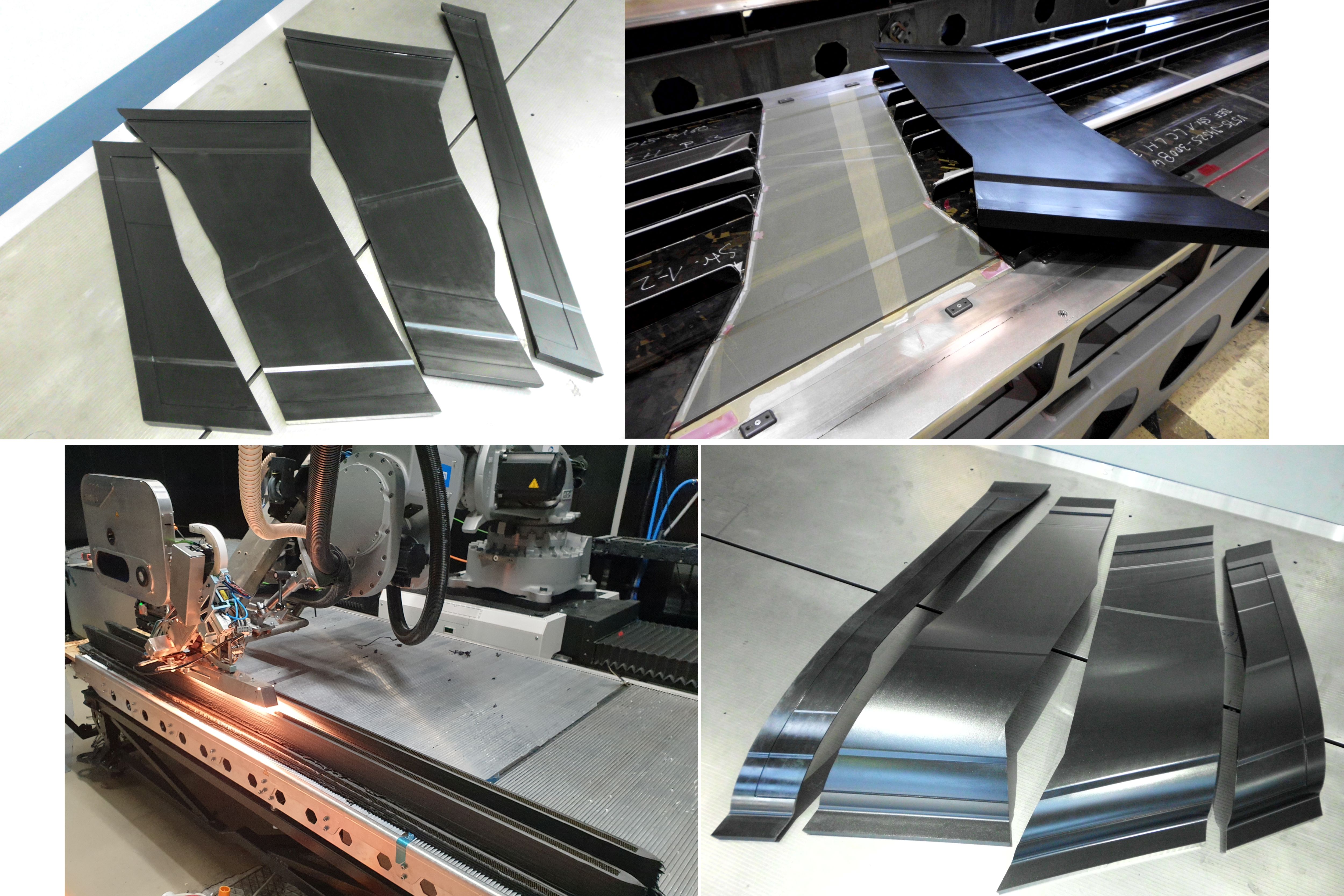
Replacing hand layup BMI intensifier tools. Intensifier tools used in serial production of A350 landing flaps were 3D printed with short carbon fiber-reinforced thermoplastic for the stringer-stiffened CFRP lower cover (tools, top left) and upper cover (tools, bottom right), also shown demolded on top of a flap cover after 180°C autoclave cure (top right). The ATLAM print head using continuous fiber (bottom left) has been developed for tools longer than 1.5 meters. Photo Credit: GKN Aerospace Deutschland, TU Munich LCC and CEAD
The light weight and durable high performance of carbon fiber-reinforced polymer (CFRP) parts is increasingly necessary to achieve aviation goals for reduced emissions. A key challenge, however, is the tooling required to mold these materials into high-quality, shaped and integrated parts such as stringer-stiffened skins. Such tools must deliver tight tolerances during high-temperature molding processes for hundreds of cycles with a thermal expansion that either matches that of CFRP parts or is managed via compensation.
In 2017, tooling was described as 3D printing’s “killer app,” offering significant reductions in lead time, material cost and manual labor. And yet, 3D-printed tools are not yet common in serial production of high-temperature, autoclave-cured parts for aerospace. However, a project started in 2019 produced 17 tools printed with short carbon fiber (CF)-reinforced thermoplastic by CEAD (Delft, Netherlands) that have been used for more than two years by GKN Aerospace in Munich, Germany, for the serial production of CFRP landing flaps for Airbus (Toulouse, France) A350 aircraft.
The team, which also includes the Technical University of Munich (TU Munich, Germany) Chair of Carbon Composites (LCC), moved a step further in 2023, unveiling the advanced tape layer additive manufacturing (ATLAM) printhead that combines continuous CF tapes with the previously used short CF materials to achieve the lower coefficient of thermal expansion (CTE) necessary for tools longer than 1.5 meters. In fact, several dozen tools used in GKN Munich’s flap production are longer than 1.5 meters, and the team is now demonstrating how to use ATLAM for their production.
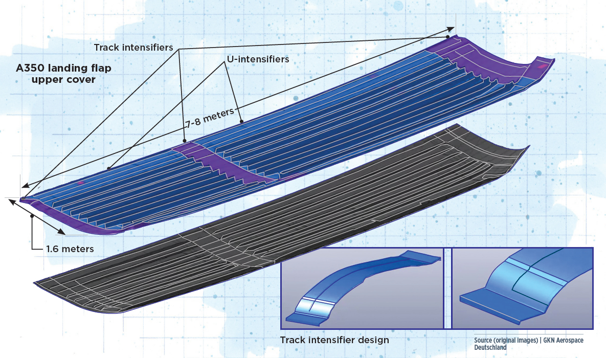
Image illustrated by Susan Kraus.
Landing flap intensifier tools
GKN Aerospace (Solihull, U.K.) is a well-known Tier 1 engine systems and aerostructures manufacturer and composites innovator. Its GKN Deutschland subsidiary in Munich supplies CFRP landing flaps for the Airbus A330 and A350 widebody aircraft. Attached to the wing’s trailing edge, landing flaps are actuated to increase the wing’s surface area and camber during takeoff and landing.
For the A350 landing flaps, which are 1.6 meters wide and 7-8 meters long depending on the specific A350 model, GKN Munich manufactures CFRP stringer-stiffened upper and lower covers for the left and right wings. These require dozens of different-sized track intensifier tools, used for areas without stringers where attachments will be made. Track intensifiers (see Fig. 2) span the width of the flap covers and are used where actuation-enabling flap tracks and cross-span stiffening ribs will be attached.
GKN Munich had traditionally made track intensifier tools using hand layup of CF/bismaleimide (BMI) tooling prepreg or conventional epoxy tooling prepreg on machined aluminum master tools. The layups were autoclave cured at 180-218°C and 7 bar of pressure in two to three stages, followed by machining of the outer 3D curved surface to a tolerance of ±0.1 millimeter.
“The process for curing the BMI tools is complicated, requiring a hot pressure debulk [HPD], a cure and post-cure cycle and also a cure cycle for the two-component epoxy wear coating,” says Frank Strachauer, project leader and R&D engineer at GKN Munich. “These tools had high material and production costs and a long lead time for manufacturing. The process was expensive, requiring significant labor time, including a lot of manual work for the bagging, and it also consumed a huge amount of auxiliary materials. The lead times were also quite long — up to several weeks for fabrication plus a minimum of 3 months for production of the metal master tools in advance.”
“3D printing offers a more efficient digital production,” he continues. “It would be a new and innovative approach for intensifiers, with potential for a large reduction in lead time and cost. It would also simplify the whole process flow for tooling, increase our production flexibility and enable recycling of the production waste and, eventually, the tools themselves.” GKN’s customer, Airbus, has been an associated partner in the resulting projects to develop this technology.
Developing a 3D-printed approach
CEAD is a pioneer in extrusion-based, large-format AM. Founded in 2014, it began development with continuous fibers in 2017. By 2019, it had commercialized its standalone robot extruders, its gantry-based, 4 × 2 × 1.5-meter continuous fiber additive manufacturing (CFAM) Prime machine and six-axis robotic Flexbot. It added milling capability to Flexbot by 2020 and announced its partnership with Belotti (Suisio, Italy) for very large CNC systems in 2021.
To begin developing the 3D printing process for intensifier tools, GKN Munich worked with CEAD to conduct a long list of printed material tests to assess strength, thermal expansion and fatigue, machinability, vacuum tightness, repairability, etc. They chose short CF/polyethersulfone (PESU) due to its glass transition temperature (Tg), which is above 200°C and thus compatible with the 180°C cure aerospace-grade epoxy prepreg for the CFRP landing flap covers.
The next step was to design the printed parts. “For the first set of prototype tools, we were using our smallest machine,” says CEAD CTO and cofounder, Maarten Logtenberg. “So, the team chose to print a full set of track intensifiers, due to their size, up to 0.6 × 1.6 meters.” These tools had a final machined thickness of 6-10 millimeters and included joggles to match the ply ramps and drop-offs in each flap cover skin.
CEAD designed the printed parts to combine left-hand and right-hand wing tools, which were then split in half and machined to final surface quality and dimensions. Photo Credit: CEAD
“We then went into this sort of development cycle, to come up with how to print all of the different intensifiers in a way that we’d have a high success rate,” says Logtenberg. “We designed the printed parts to combine both left-hand [LH] and right-hand [RH] wing tools in the same complex-shaped, closed contours, which allowed continuous printing.” Eight printed parts produced all four intensifiers — End Rib, Rib 1, Track 1 and Track 2 — for the upper and lower flap covers for LH and RH wings. After printing, the closed contour parts were split in half and then machined.
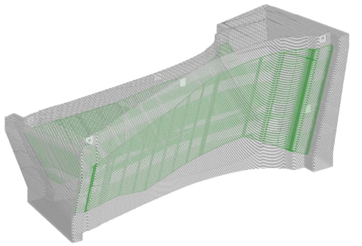
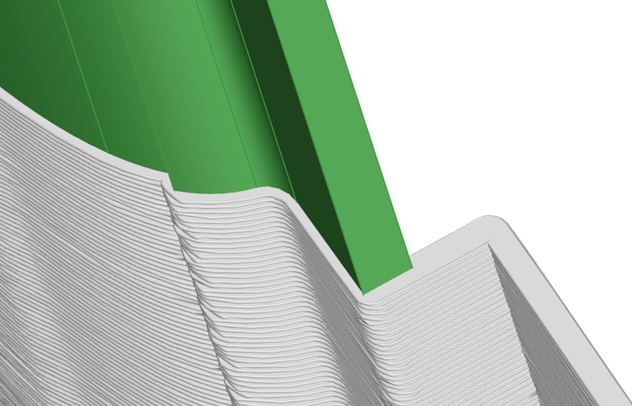
Figure 1. Printed beads, machined tools. CEAD software enables modeling the print beads (gray) together with the final, machined part (green) to verify sufficient material is available for machining the printed parts to the final surface and dimensions required for the production tools. Photo Credit: CEAD
The printed parts were slightly oversized, ensuring the additional material required for machining to the final surface quality and tolerances. “We were able to improve our slicing and printing simulation software so that we have the capability to offset any surface a certain amount,” explains CEAD software engineer Jasper Klein Mentink, “and then view a model of the print beads together with the final part [Fig. 1]. In this way, we can precisely verify whether there is sufficient material to remove to achieve the final product dimensions. The software can quickly iterate designs and helps us to ensure prints are ‘first time right,’ which saves a lot of time and material. Additionally, the printed bead model can be imported into CAM software to aid the milling process.”
“The 3D printing process for the initial set of intensifier tools was very fast,” says Logtenberg, “between 160 and 420 minutes for each of the eight parts depending on its size and complexity. The milling, however, was a bit of a challenge, as we didn’t have in-house capability at that time, and had to rely on an outside company. But it worked out and we successfully completed the first full set of prototype intensifiers.”
There were important lessons learned as well. “During the production of the first set of track intensifiers, it became apparent that the printing process and subsequent machining caused material distortions due to internal stress,” says Strachauer. “This can be countered by printing with sufficient oversize to allow the residual distortion in machining to be removed. In addition, the milling tools, milling parameters and a correctly selected and part-adapted milling strategy also play a decisive role in achieving exact dimensional accuracy of the tools.”
Proven process, results
GKN Munich used this set of 3D-printed track intensifier tools to produce full-sized test flap covers in mid-2019. The resulting CFRP parts passed all required quality checks, including microscopic void analysis and ultrasonic inspection to validate the laminate thickness and quality.
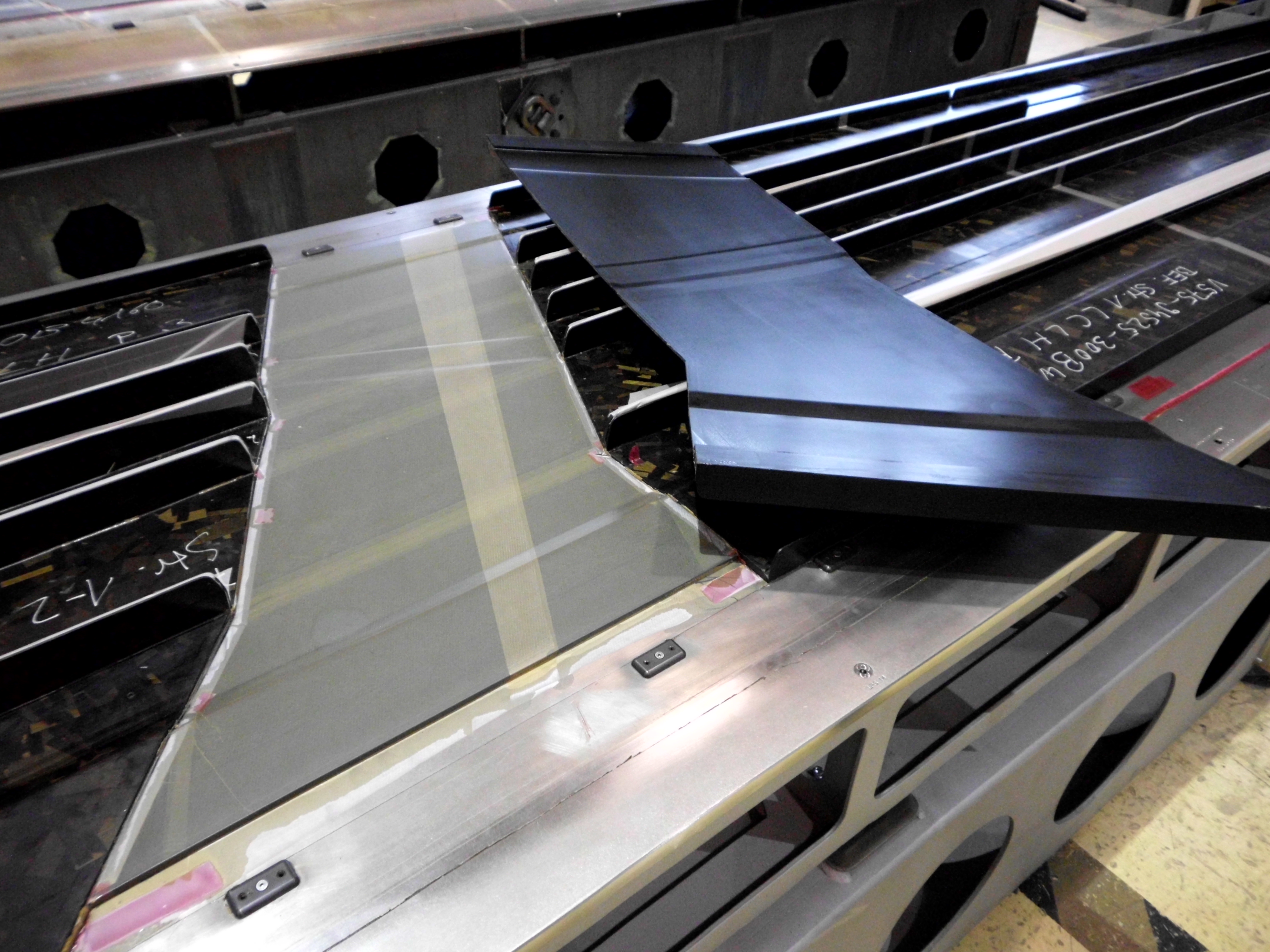
Figure. 2. Two years in autoclave parts production. Qualified 3D-printed track intensifier tools, shown here demolded from a flap lower cover after autoclave cure, were implemented into GKN Munich’s serial production of landing flaps starting in early 2021. Photo Credit: GKN Deutschland
After completing qualification of the 3D-printed intensifier tools, GKN implemented them in serial production of A350 landing flaps in early 2021 (Fig. 2). The tools have now been in use for more than two years.
“This is groundbreaking for the industry,” says Strachauer. “We were able to show a major cost reduction and lead time reduction versus the previous tooling. We have also eliminated the need for master tools, autoclave cure and manual layup. The 3D printed intensifier tools have shown increased accuracy and quality due to a fully automated printing and machining process.” He also notes their thermoplastic construction enables repair and recycling options not possible with the previous thermoset-based systems.
However, the 3D-printed tools fell short in one area. “We did a lot of research with GKN and TU Munich in terms of thermal expansion,” says Logtenberg, “and we discovered that up to roughly 1.5 meters in length, you can print the tooling without any continuous fiber — so, just extrusion of short fiber-reinforced pellets. But for tools longer than 1.5 meters, the CTE is too large, and it becomes difficult to compensate for the thermal expansion.” Note, more than 80% of the tools GKN Munich uses to produce the outboard landing flaps are longer than 1.5 meters.
The next step: Continuous fiber
“We knew we could reduce the CTE by using continuous fiber,” says Logtenberg, “and we already had quite a lot of experience with continuous fiber printing through our CFAM technology.” CFAM combines chopped and continuous fiber materials inside the 3D printing nozzle. “So, our first prototypes for longer tools were based on that as well. But due to the high processing temperatures of the thermoplastics needed to withstand autoclave cure and the high modulus of the continuous carbon fiber, it was difficult to achieve the right impregnation of the material with the quality and reliability required for aerospace tools.”
Even though CEAD used the same matrix material for continuous fiber unidirectional (UD) tapes and short fiber pellets, the optimal processing conditions for each were different. “For example, you could be within the required temperature range for the matrix, but the tape would be too soft, while the extrusion material was not hot enough,” explains Logtenberg. “We were continuously struggling with how to manage the process. Finally, we came up with the idea to separate the material processes. They are still combined as we move the print head, but we first extrude the short fiber layer and the pre-impregnated tape with the continuous fiber comes right after. This gives us full control of processing the tape as well as extrusion of the short fiber material.” This is the ATLAM process and print head.
“Once we were able to prove the feasibility, GKN established a public-funded research project,” says Logtenberg. TU Munich was also included, performing research in thermal expansion, laminate quality and voids. Also involved was machining technology firm Hufschmied (Bobingen, Germany), exploring how to machine the printed raw parts.
In 2021, GKN Munich and CEAD submitted patent applications, worked through 2022 to further refine the equipment and printed the first proof of concept tooling parts in early 2023. “This development has taken two years,” says Logtenberg, “but we have finally succeeded in a reliable process that enables large-scale autoclave tools with a sufficiently low CTE.” Strachauer further details: “It is close to Invar in the print direction and the same value compared to BMI tooling prepreg.”
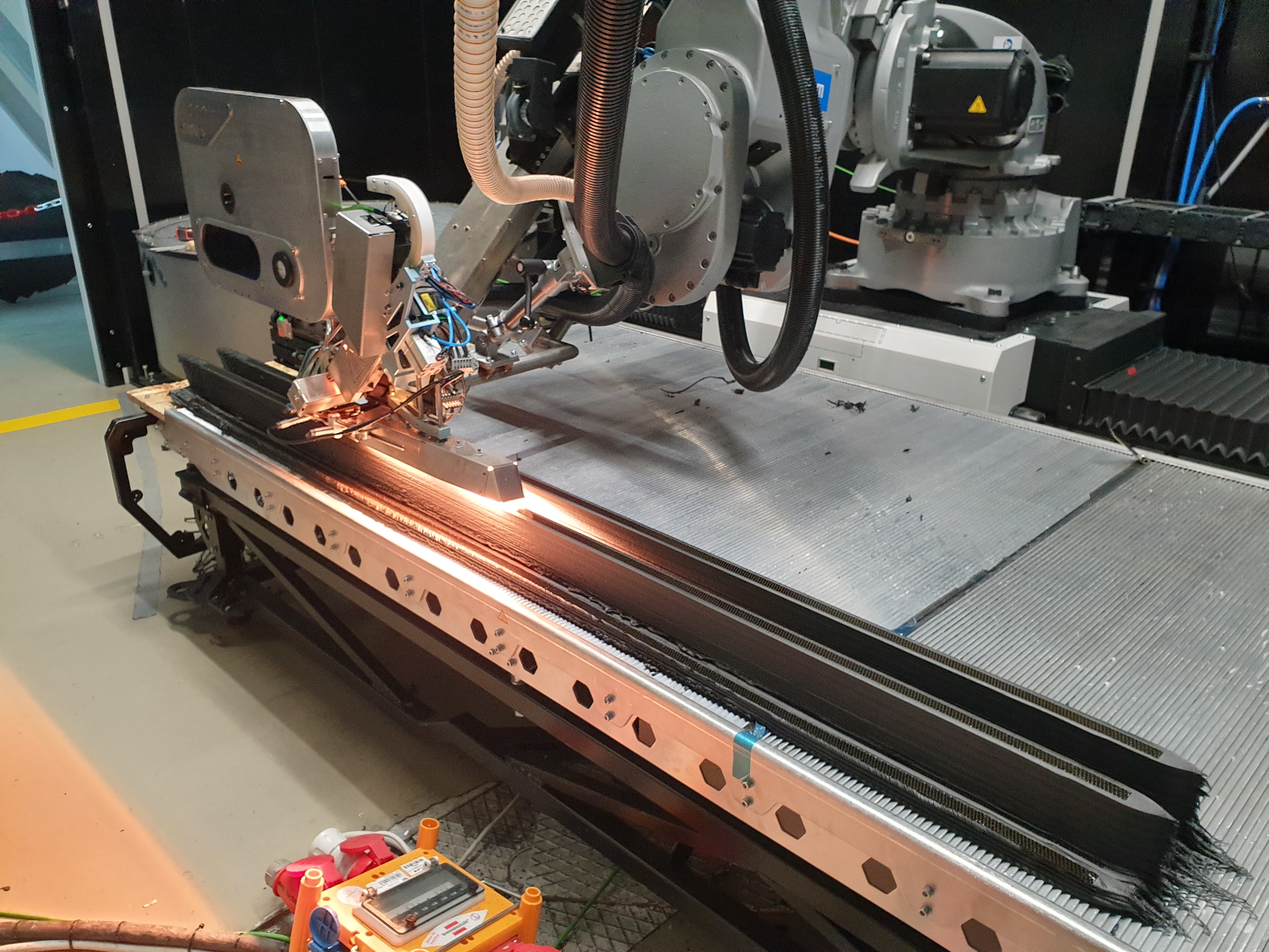
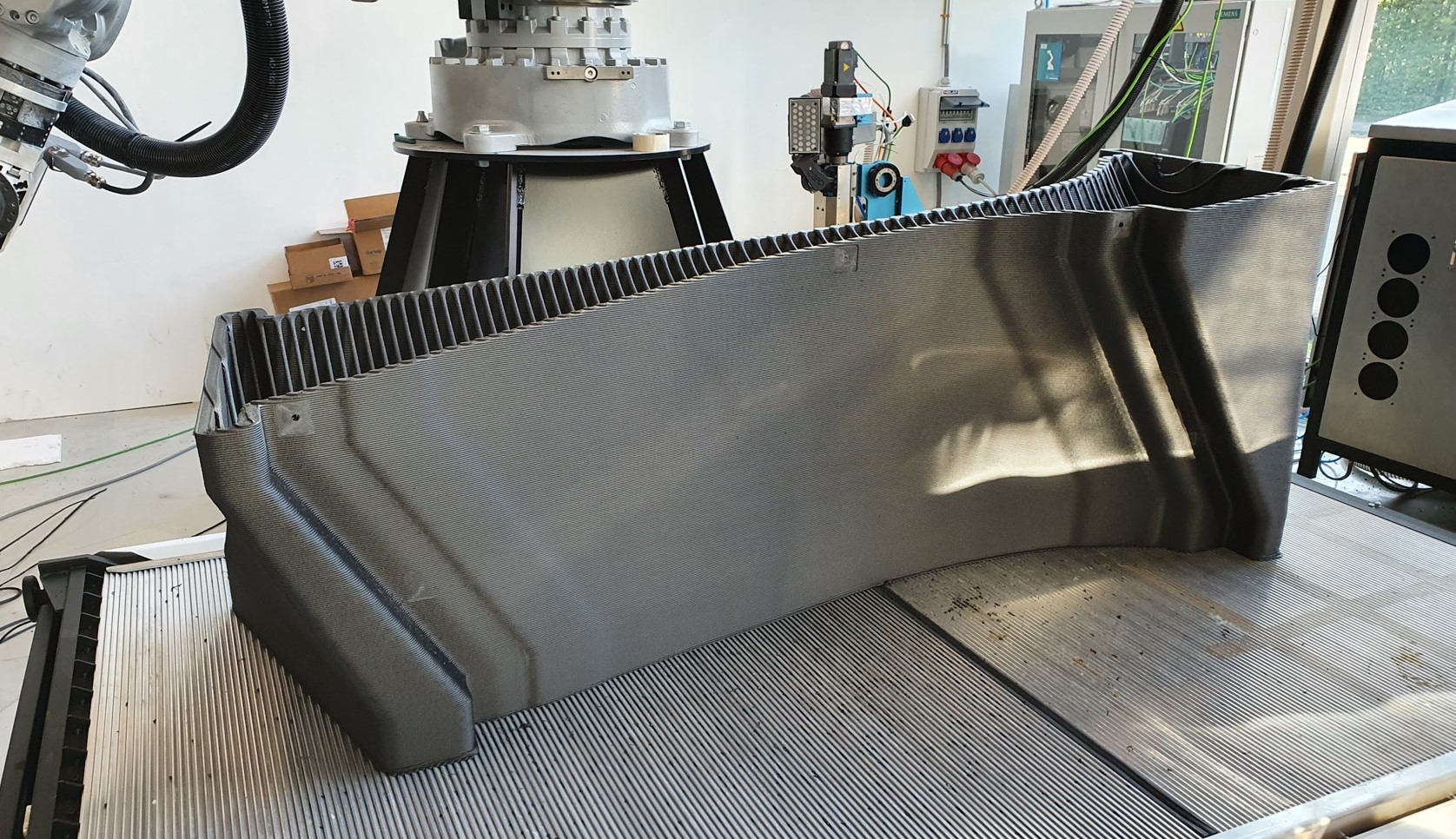
Figure 3. ATLAM for lower CTE, longer printed tools. The ATLAM process and print head extrudes short fiber thermoplastic material followed immediately by continuous fiber tape, achieving a sufficiently low CTE to enable autoclave curing tools longer than 1.5 meters. Shown here is the first 2.2-meter-long part for GKN Munich U-intensifier tools, 3D printed using ATLAM at TU Munich. Photo Credit: GKN Deutschland, TU Munich LCC.
CEAD officially launched ATLAM at JEC World 2023 (April 25-27, Paris, France), where it showed a third-generation ATLAM print head, says Logtenberg. “Every iteration represents a significant improvement, and we will continue advancing the technology. We have designed ATLAM with sensors and control possibilities that TU Munich uses to measure the impact of process parameters on the finished print CTE, modulus, voids, etc. They want to nail down what the best processing parameters are for various material options. Meanwhile, we are mounting ATLAM on our next generation of robots in-house so that we can start producing sample parts.”
Future tooling, challenges, markets
Will these next prints include some of the longer intensifier tools for GKN Munich? “We’re working on that now,” says Logtenberg. There are also other options. For example, Airtech International (Huntington Beach, Calif., U.S.) is 3D printing large-scale tools as part of its Tooling of Tomorrow (TOT) business. It has dedicated 3D printing facilities in Springfield, Tennessee, and Luxembourg, Europe, as part of its vision to advance AM composites through its technical expertise and Dahltram 3D printing resins.
“We’re already talking about how we can continue to strengthen our collaboration with Airtech,” says Logtenberg, “because we’re using a lot of their 3D printing resins, which are good materials that work very well in our machines.”
“We are also looking for two or three other research partners to implement ATLAM,” he adds, “because there is still more research needed. This market is difficult for new technologies to be adopted and fully utilized. So, it’s important to show what can be done with ATLAM, using various materials and combinations of short fiber and continuous fiber layers, to explore the possible solutions that can be achieved. And we still have some challenges to tackle, such as the software for programming toolpaths, because ATLAM is entirely different than anything that’s out there right now.”
For GKN Munich, the 3D-printed track intensifier tools and upcoming U-intensifiers printed with continuous fiber represent two stages of its AM roadmap for fiber-reinforced thermoplastic composites. “This is only the beginning of a new era of 3D-printed tooling for high-temperature autoclave curing of structural composite parts at GKN Aerospace,” says Strachauer. “We will also look at producing layup tooling and expand to other families of tooling as we move toward developing structural parts printed with continuous fiber. Additive manufacturing at GKN Aerospace — across both engines and aerostructures technology — is being expanded all the time to open new applications and new markets.”
Logtenberg agrees. “Additive manufacturing will become better and more mature every year, as we are seeing with new support and materials from companies like Airtech and new developments in software, which will enable new capabilities. I think the work we have done with GKN Munich and TU Munich has helped set us apart and positioned us to help create such new technologies. We are growing and the market for additive manufactured composites is still growing — every day we learn about new applications and see the opportunities they open for the future.”


.jpg;maxWidth=300;quality=90;format=webp)
Related Content

Novel dry tape for liquid molded composites
MTorres seeks to enable next-gen aircraft and open new markets for composites with low-cost, high-permeability tapes and versatile, high-speed production lines.
Read More
PEEK vs. PEKK vs. PAEK and continuous compression molding
Suppliers of thermoplastics and carbon fiber chime in regarding PEEK vs. PEKK, and now PAEK, as well as in-situ consolidation — the supply chain for thermoplastic tape composites continues to evolve.
Read More
Materials & Processes: Fabrication methods
There are numerous methods for fabricating composite components. Selection of a method for a particular part, therefore, will depend on the materials, the part design and end-use or application. Here's a guide to selection.
Read More
Infinite Composites: Type V tanks for space, hydrogen, automotive and more
After a decade of proving its linerless, weight-saving composite tanks with NASA and more than 30 aerospace companies, this CryoSphere pioneer is scaling for growth in commercial space and sustainable transportation on Earth.
Read MoreRead Next

Demonstrating functionalized, cost-effective composites using additive extrusion
Hybrid thermoset/thermoplastic composite part with 3D-printed functionalization demonstrates technology possibilities and EmpowerAX open platform offering expertise from members throughout the process chain.
Read More
Robotized system makes overmolding mobile, flexible
Anybrid’s ROBIN demonstrates inline/offline functionalization of profiles, 3D-printed panels and bio-based materials for more efficient, sustainable composite parts.
Read More
Metal AM advances in composite tooling, Part 2
Toolmakers and molders continue to realize the benefits of additive versus conventional/subtractive manufacturing of molds and mold components.
Read More