
Automated Preforming, Part 5: Holistic Quality Optimization
Simulation and testing key to integrated approach for optimization of automated preforming, offering time and cost savings as well as basis for automated quality inspection.


This is part five of a seven-part series about preforming. For more on this series, click the links below:
part one, part two, part three, part four, part six, part seven.


Also, don’t miss the printed version of this series:
Preforming Goes Industrial, Part 1 and Part 2.
This blog comes from my discussions with CIKONI (Stuttgart, Germany), a composites design and engineering firm that provides a range of services, including drapability simulation, testing and process development for automated preforming.
CIKONI’s use of active interlayers to reduce or eliminate wrinkles during preforming was covered in the printed series. Its development of Holistic Quality Optimization (HQO) was not. So that’s what I will delve into here.
The foundation of HQO is that achieving high quality in carbon fiber reinforced polymer (CFRP) parts depends on managing complex interactions between the part geometry, mechanics, constituent materials—fabrics, in the case of preforming—and process. CIKONI asserts that simulation is key to understanding these interactions and should be used throughout an integrated design and process development approach.
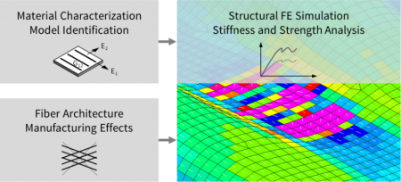
Developing optimized preforms for CFRP parts requires understanding and managing complex interactions between part design, constituent materials and manufacturing process(es).
SOURCE: CIKONI
Optimization of automated preforming requires coupling structural and process simulation. For example, draping simulation enables characterization of the formed fabrics, including, for example, shear behavior, effects from binder materials and the interaction between these factors. This then provides leads for possible optimization strategies. Testing to validate simulation results and evaluating fabric formability is then fed back into the computer models and aids in refining the process and part design.
The four main pillars of HQO are process planning, manufacturing, defect analysis and structural analysis, noting that there must be an exchange of information between all of these. “The idea is to make this a closed loop from part design to process and from process to quality management,” says CIKONI co-founder Dr. Farbod Nezami.

The four key pillars of the CIKONI Holistic Quality Optimization process, noting that each of these requires an exchange of information with the others.
SOURCE: CIKONI
Testing
If simulation is the first set of tools key to HQO, testing and defect analysis is the second. “The DrapeTest developed by Textechno is a good tool for comparing fabrics to each other in a standardized way,” says second CIKONI co-founder Jan-Phillipp Fuhr, “but it is not so suitable for characterizing all of the fabric parameters needed for holistic optimization.” Instead, CIKONI has developed a set of special tests. “The first is picture-frame testing, which uses a picture frame we have developed to characterize fabric shear behavior under process conditions,” notes Fuhr. A second set of tests characterizes bending behavior and allows calculation of bending stiffness. A third test measures friction between the tool and the preform and from ply to ply as well as anisotropic contact behavior, for example from a 0-degree ply to a 90-degree ply. Fuhr explains, “A unidirectional ply within a preform stack will always create problems because it behaves differently, presenting anisotropy as well as friction.” He points out that there are no standards for these tests accepted by the whole industry yet. “Right now, every player uses his own machines, so it makes it hard to compare test results.”
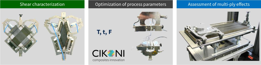
Testing such as the picture-frame testing for fabric shear behavior is key in evaluating the parameters necessary for optimizing the preforming process and finished composite part.
SOURCE: CIKONI
Optical Measurement
Another key tool is optical measurement of fiber angles in the preformed fabric. This enables assessing the impact of processing and measurement of the resulting shear angles in the preformed fabric, which can then be plugged back into part and process simulations for optimization. It also is used to program optical systems for quality assurance (QA) in the finalized part manufacturing process.
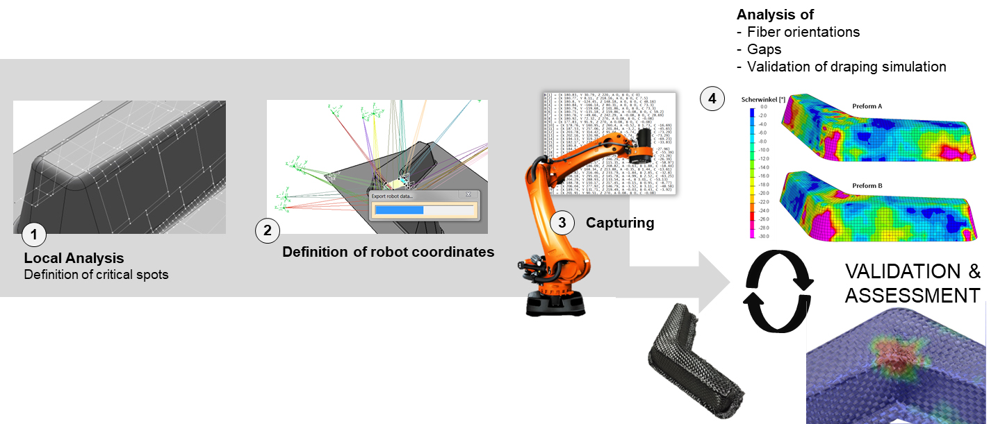
Robot-assisted 3D fiber angle measurement is another key tool in optimizing automated preforming.
SOURCE: CIKONI
Simulation and Testing Save Time
When asked about the time and cost of performing simulation and testing, Nezami explains, “In Germany, we have similar engineering costs as in the U.S., but over the last few years, German automakers have tried to understand what is happening in these preforming steps. So now, many automotive companies outsource draping simulation. This actually saves costs because it saves time during process development and reduces iterations in tool design.”
Nezami notes this is especially beneficial for larger and more complex structures, “because if there is a breakdown in one part, that presents a bottleneck for the whole assembly, and holds up development of all the other parts.” Automotive manufacturers typically introduce a new model every three years, he adds, “so development time is crucial. Tools and machine parameters have to be detailed within a fairly short cycle. There is no time for additional iterations on all of the process and tool engineering.”
Fuhr claims that the simulation and testing approach—the HQO process—cuts cost dramatically vs. the process of building a mold and draping the fabric to provide feedback. He says this is one reason why the strategy of automotive OEMs and others has been to choose a specific set of materials to use—unidirectional and noncrimp fabrics (NCF)—and characterize these so that they understand their behavior in preforming. “Then they don’t have to do this step again,” he explains. “They use this same set of materials for every new model, which then achieves cost savings.”
Simulation already has a well-established history in crash testing, where each test can cost millions of dollars. Nezami adds that German car makers also have a long history in process simulation before finalizing production: “For example, in sheet forming, it is state of the industry to optimize blank forming virtually before you start sheet metal forming.”
Complex Processing
“Not every part should start with finite element model (FEM) draping simulation,” says Nezami. “It is important to look at the parts and decide which need this approach. You need to ask, ‘Is it bringing my development forward, or can we use a simpler approach?’ So, for example, if you compare some of the automotive parts, the complexity is very high vs. aerospace, which tends to use less complex geometry, though aerospace part quality requirements are high. Also, with low-volume production, you won’t be using an RTM and preforming process.”
Fuhr describes this further, “There is an equation to be considered which includes the part production volume and what process to use for preforming. The critical complexity is not one of multiple layers or ply buildups and drop-offs, but instead a question of geometrical form that constrains certain solutions. These are not as common in aerospace as in automotive. It is important to note, however, that when you do draping simulation, you are not replacing the need for detailed laminate and structure design. You are doing these two hand-in-hand.”
So how long does this type of testing and simulation take? “This is always a hard question to answer,” Nezami replies, “because each manufacturer and process is different. But, in general, you can get very far in six months if you start from zero. You can always speed up this process if you have a good partnership and if everything moves straightforwardly.” There are also possibilities for shortcuts. “Sometimes during the initial discussions, we can do some simple steps to reduce fiber waviness and wrinkles,” Nezami explains. “So the full HQO is only for the most complex geometry parts which also need high quality.”
Validation as Basis for Quality Assurance
CIKONI shows validation of simulation and structural analysis at the end of the closed loop HQO process schematic. “Ideally, structural analysis and validation are done quite early in the process,” answers Nezami. “We were showing how it can make QA at the end of the process more efficient as well.” He explains that in automotive applications, crash always has to be considered. “In fact, it is the most important driver during development,” he points out. Thus, defects in the preform which then lower the part performance in this ultimate loading are not acceptable in a part that is indeed optimized. “So you cannot just say ‘we’ll stay 50 percent away from the strength limit of the materials in this part during crash loading’ because it would make the part, and ultimately the car, too heavy. We wanted to show what fiber deviation is allowed in a specific field of the part—for example, you can have 5 degrees of fiber angle deviation here but not here—because all fields are stressed differently during a crash.” Nezami says this type of correlation between localized fiber angles and overall part performance is not done always yet, “but it’s the ideal way because it enables automated quality inspection.”
An example of using fiber angles as a basis for automated quality inspection can be seen in the Apodius AVS 3D system which uses 3D scanning and fiber orientation measurement to achieve automated defect detection in NCF preforms and parts.
Fuhr notes that this last point is important because no preform looks exactly like another one even with automated preforming processes. “So you have to be ready for this dynamic character of the process. Our approach enables realistic QA limits.” He says that idealized limits can be too tight, which then makes parts too expensive because there are too many rejections and the process yield is low.
Note: This was also pointed out to me recently by David Maas, a longtime composites industry veteran and consultant working on automated fiber placement technologies. He agrees that as automated inline inspection systems become widespread, there will initially be issues with low yields because we haven’t yet learned how to set realistic QA limits vs. more abstract limits drawn from “idealized” process and product specifications.
Holistic Quality Optimization for Composites
Nezami and Fuhr say that the automotive industry currently has the most developed and industrialized understanding of preform characterization via testing and simulation in order to optimize the part design and production process.
“We are proposing that this HQO is the same approach that should be used to handle the design complexity of composites in general,” says Nezami. “With composites, there are too many design freedoms, parameters and their relationships to each other to explore without simulation. Only if the product and process engineering are developed hand-in-hand can we actually understand what we are producing.”
For more details, click here to read Farbod Nezami and Diego Schierle’s presentation from the 17th European Conference on Composite Materials (ECCM17, June 26-30, 2016) in Munich, Germany. CW has also posted a powerpoint presentation based on this paper. For more on CIKONI’s developments in additive manufacturing, click here.


Related Content

Modular approach to material card development of composites
Forward Engineering GmbH walks through a modular testing and simulation approach for automotive/aviation composites enabling more accurate material selection earlier in the design phase.
Read More
Generative Orthoses project to reshape orthopedic care
CRP Technology, MHOX and Istituto Ortopedico Rizzoli, one of the winners of the WORTH Partnership Project II, have developed bespoke orthoses using generative design, Windform GT fiberglass materials and PBF.
Read More
Taniq software helps European student team WARR fly its Type 5 pressure vessel
SNAPSHOT: The filament-wound composite vessel, designed and manufactured using Taniq's TaniqWind Pro software, successfully flew aboard the EX-4C rocket at the European Rocketry Challenge in late 2025.
Read More
Next-gen fan blades: Hybrid twin RTM, printed sensors, laser shock disassembly
MORPHO project demonstrates blade with 20% faster RTM cure cycle, uses AI-based monitoring for improved maintenance/life cycle management and proves laser shock disassembly for recycling.
Read MoreRead Next

Automated Preforming, Part 4: Drapability Testing
Textechno discusses how this test works, the new German test standard and its benefits for composites
Read More
Automated Preforming, Part 6: Coriolis Composites
Pioneer in automated fiber placement (AFP) advances preforms for overmolded thermoplastic composites enabling production of one automotive part every 20 seconds.
Read More
Dialing in composites performance via dynamic digital twins
Sport Dynamics Lab uses Flexdynamics testing, digital models and AI tools to compare designs, materials and systems, enabling optimization with potential for propellers, drones and vibrational structures.
Read More