
Automated Spar Forming
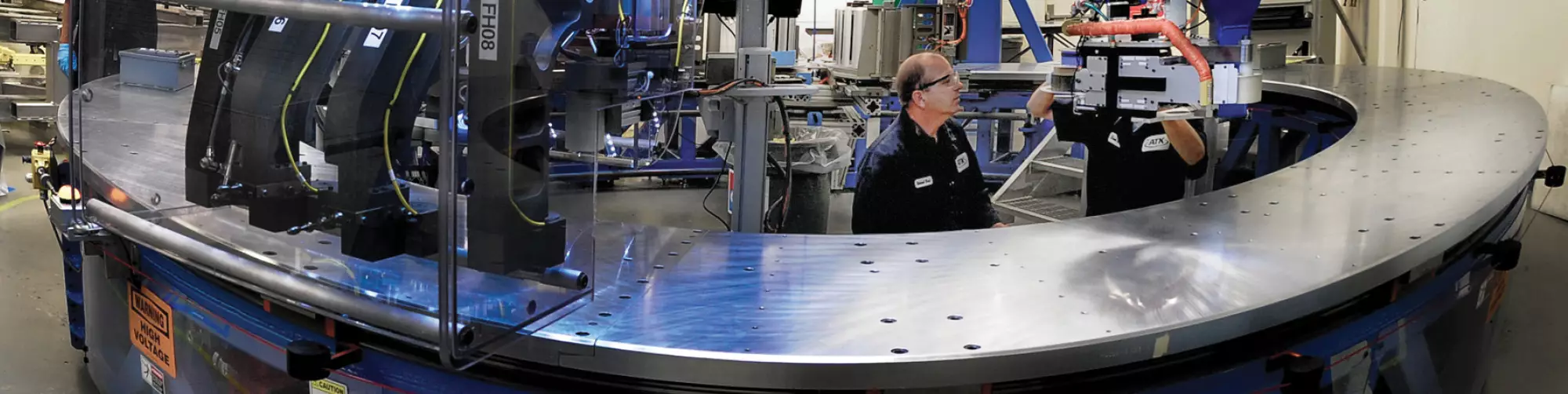
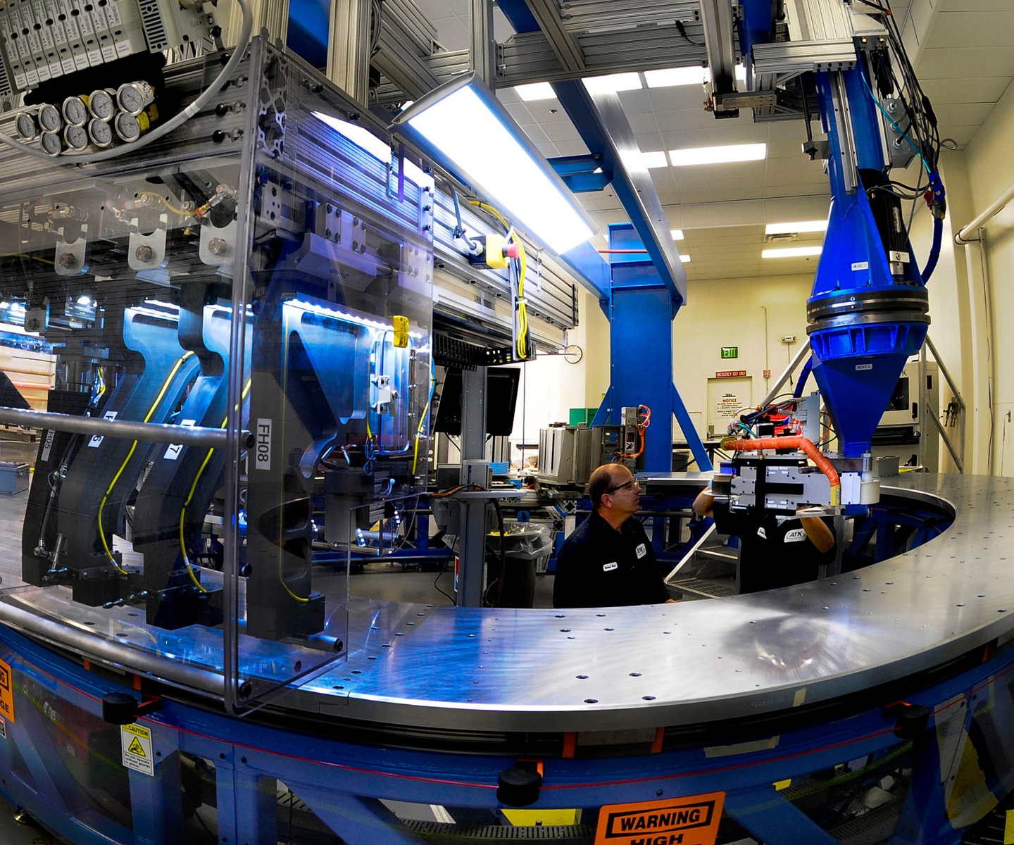
For radial components, the Automated Spar Forming Machine is oriented around a donut-shaped steel rotary table that rests horizontally on the shop floor.
Source: NGIS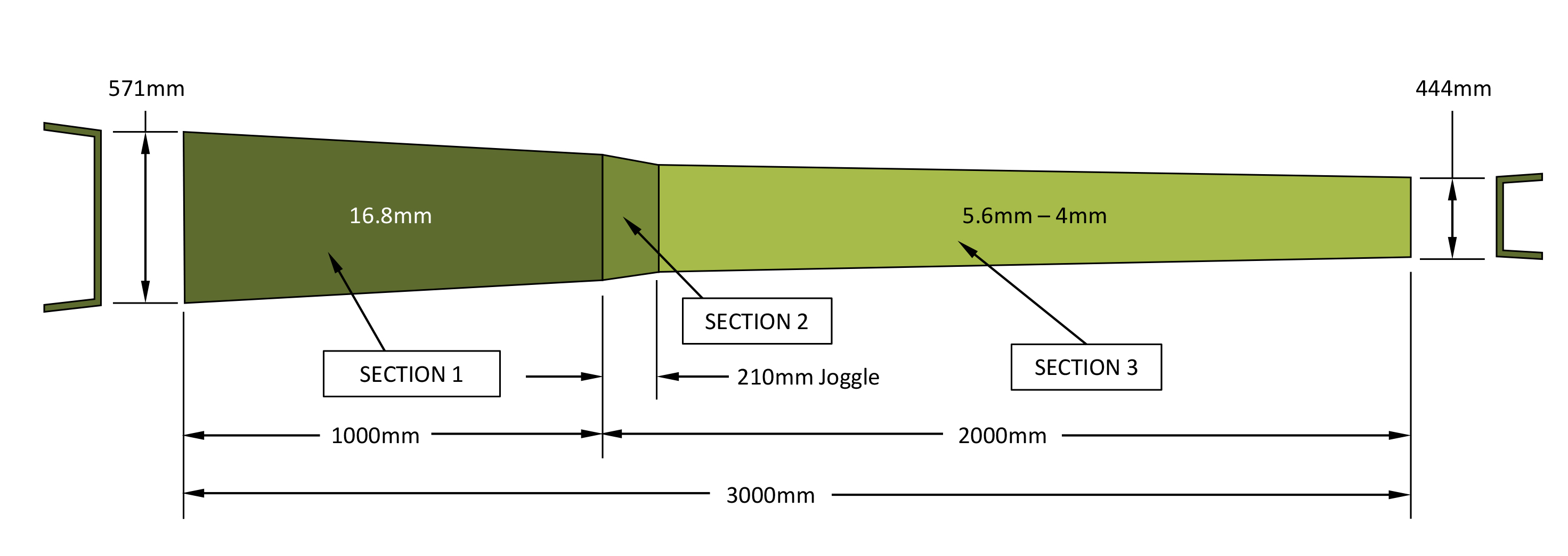
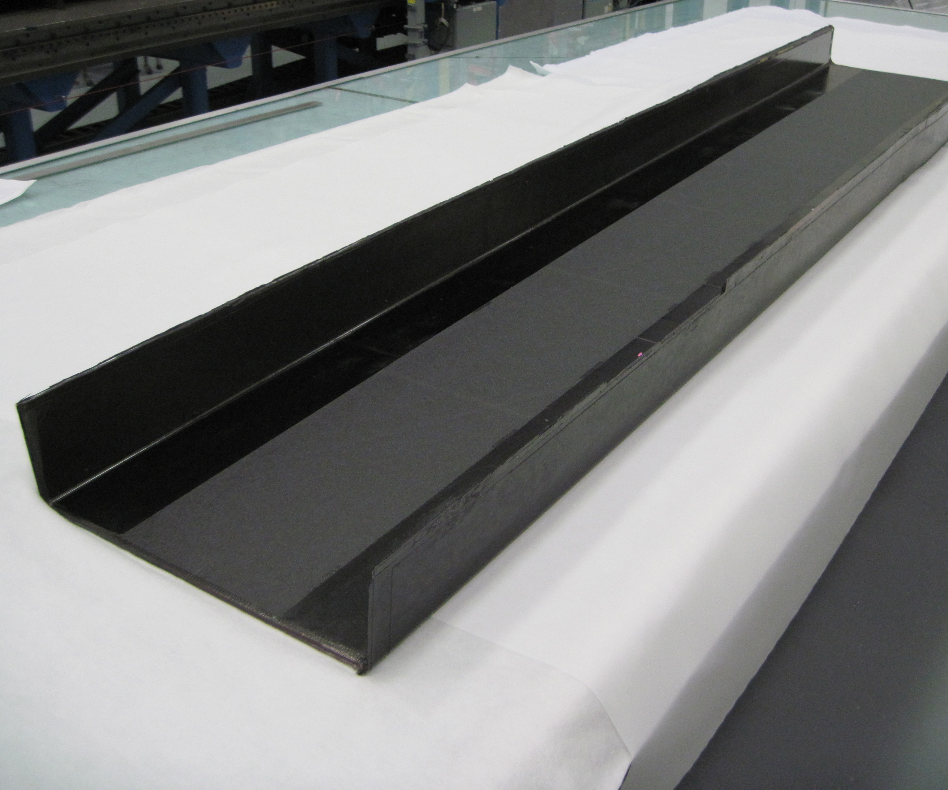
Challenging demonstrator
The 3m/9.8 ft long spar demonstrator that NGIS built using the new ASF process deliberately includes the most challenging geometric features, including a variety of flange angles, radii, thicknesses and fiber angles.
Source | NGIS
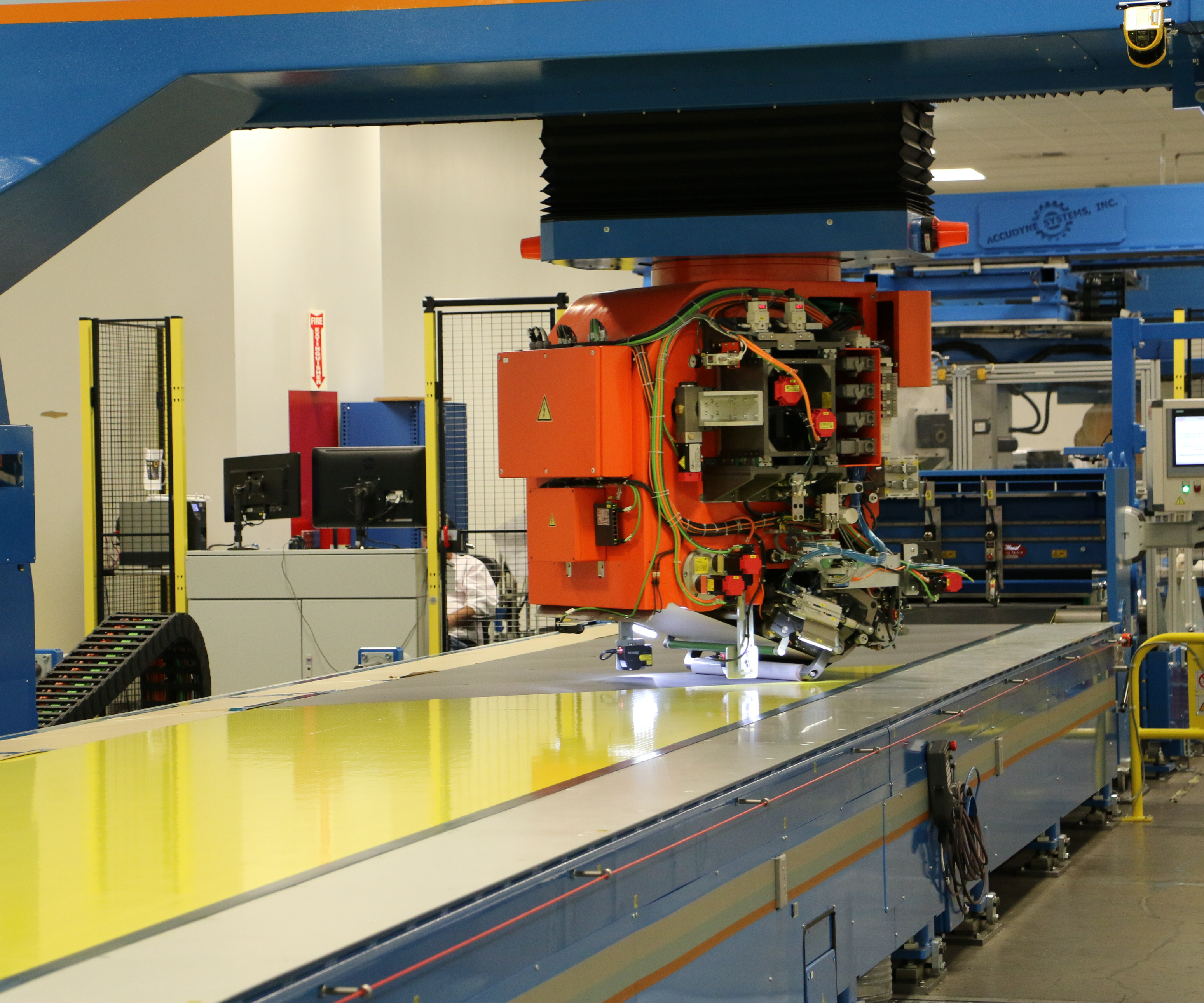
Step 1
Material is prepared for Automated Spar Forming on a Material Preparation Machine, which unrolls, collates, re-orients and re-rolls prepreg.
Source | NGIS
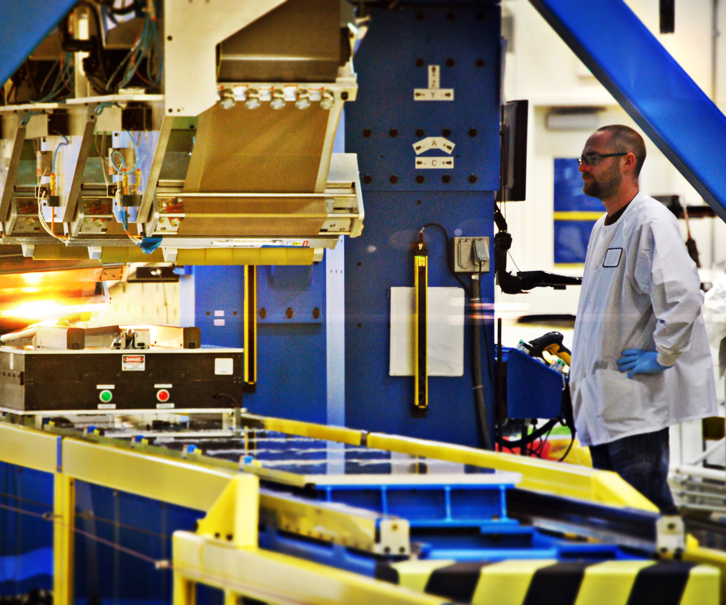
Step 2
As it lays down material, the linear Automated Spar Forming Machine (ASFM) passes a series of rollers and forming devices over the material, simultaneously compacting and debulking it tightly against the tool and underlying laminate, so that separate debulk cycles are not required.
Source | NGIS
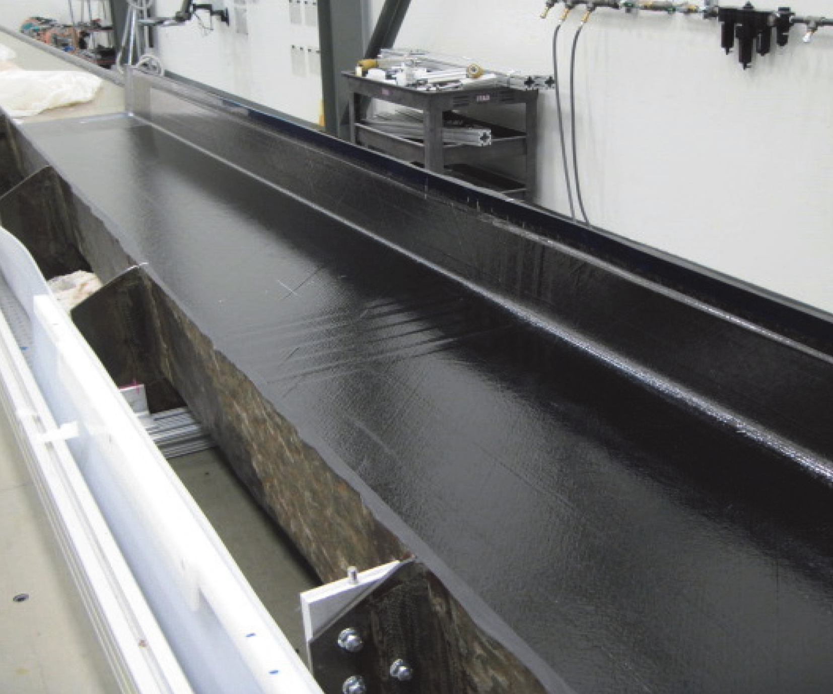
Step 3
ASFM rollers and forming devices work effectively on all part surfaces, including vertical and horizontal features as well as radii. The demonstrator spar’s joggle is visible in the center of the image.
Source | NGIS
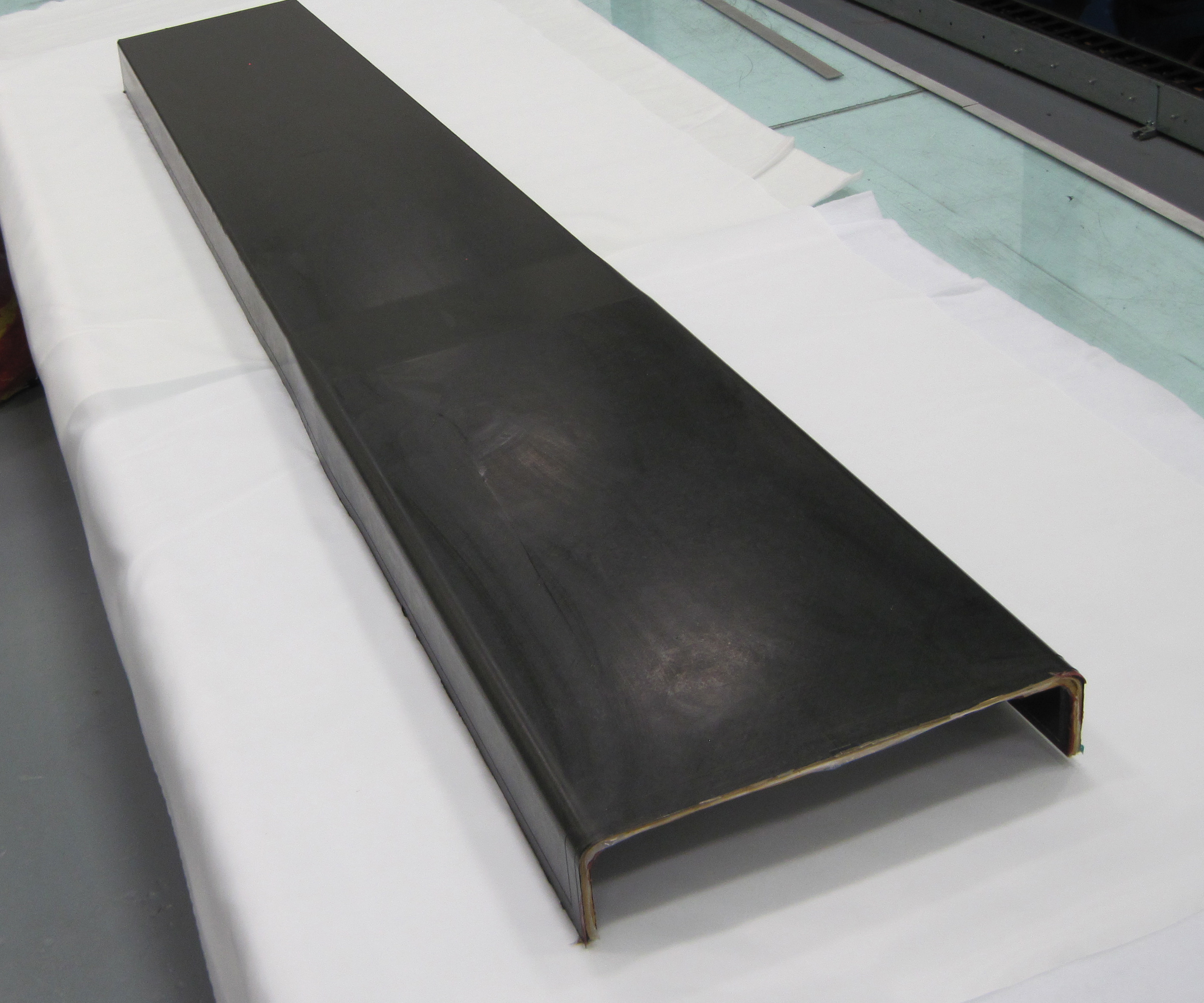
Step 4
A view of the spar OML (outside mold line) shows the joggle region, where ply drop-offs were required to create the structure properly.
Source | NGIS
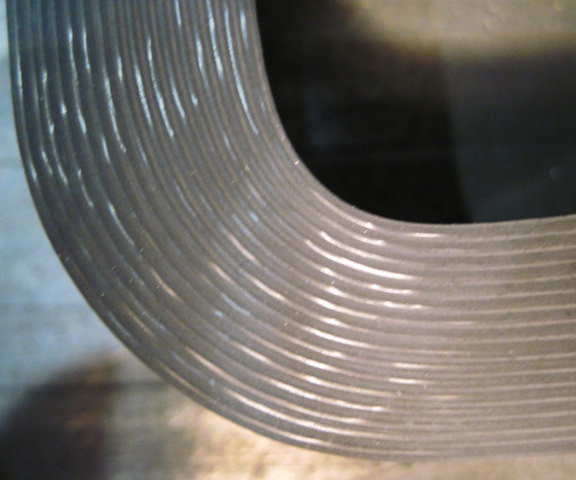
Step 5
ASF rollers and forming devices maneuver effectively through radii in female molds. Images shows consistent compaction in a cross-section of the spar web flange radius.
Source | NGIS
Step 6
The finished demonstrator spar proved ASF to be a viable and cost-efficient alternative to automated fiber placement. NGIS is working toward its adoption in next-generation aircraft programs.
Source | NGIS


“Innovation Systems” seems an apt moniker for Northrop Grumman’s (Falls Church, Va., U.S.) newest business sector. Formerly Orbital ATK, the business claims a rich history of new technologies for aerospace composites manufacturing — technologies that have increased part consistency and accelerated production speeds by automating fabrication processes. One of the most recent innovations developed by Northrop Grumman Innovation Systems’ (NGIS) Aerospace Structures Division extends an existing manufacturing method for aerospace stiffeners to the fabrication of spars and other wider, thicker components with more complex geometries.
Starting with stiffeners
When one of NGIS’s predecessor companies (Alliant Techsystems) developed the patented Automated Stiffener Forming Machine (ASFM) back in the early 2000s, the technology easily raised the bar for both quality and cycle time; it was the first automated composite stiffener fabrication process to replace hand layup. The Automated Stiffener Forming (ASF) process, which makes both linear and radial airframe structures, achieves superior compaction and repeatability at production rates nearly 10 times that of the traditional hand-layup process. The advantages ASFM offered were quickly recognized, and the company landed multiple contracts with aerospace OEMs, including Airbus, to which the company shipped its first ASFM-built components in mid-2010. Using ASF and automated material preparation production lines, NGIS currently produces approximately 33 kilometers of A350 XWB composite components per month based on a build rate of 10 aircraft, and has the capacity to produce more than 40 kilometers per month. As of January 2019, the company has completed more than 250,000 composite parts in support of the A350 XWB program.


A companion technology to ASF, aptly named the Material Preparation Machine (MPM), converts unidirectional (UD) tape — currently HexPly carbon fiber prepreg tape from Hexcel (Stamford, Conn., U.S.) — to the material form the ASF machines use (Step 1). One MPM supplies material to multiple ASFMs. The MPM unrolls prepreg tape, up to 600 millimeters wide, from rolls up to 600 meters long, and passes it through a proprietary collation system, which creates flags — the term for job-specified lengths — of prepreg at bias angle cuts from 10 to 90 degrees. The system then re-orients each flag to a pre-programmed angle, puts it back in line with the other flags onto a continuous carrier, and re-spools the re-oriented material. The new prepreg roll comprises a series of UD flags oriented at a specified angle and width needed to meet specific design requirements of the stringer or frame to be produced. The MPM also has slitting capability to make multiple narrower rolls during one material preparation run. The slit spool widths can be optimized for part geometry, helping to keep material waste reportedly under 15%.
After it leaves the MPM, each roll is delivered to a cleanroom, where it is loaded onto an ASFM. Parts are laid up on the ASFM in a relatively simple and rapid process: the mold passes under a material placement station and a series of compaction stations, which accurately place the material onto the tool surface and conform/compact it into the shapes, angles and dimensions needed for the particular stiffener being formed (Step 2). During this process, ASFM dispenses carbon fiber prepreg tapes or dry fiber formats into the female spar tool from a selected supply head with the proper angle orientation(s) and width. As tapes are laid, a series of rollers and forming devices pass over the material/tool, simultaneously compacting and debulking the material tightly against the tool/underlying laminate, so that separate debulk cycles are not required. The rollers work all surfaces of the part: horizontal, vertical, radii, etc. “It is a progressive roll forming process on one forming head,” summarizes Vern Benson, technical fellow in composites automation at NGIS.
For radial components, the ASFM is oriented around a donut-shaped steel rotary table that rests horizontally on the shop floor. The appropriate mold is secured to the table, which then rotates to the machine’s tape-laying station. A robot — currently one from Kuka Robotics Corp. (Shelby Township, Mich., U.S.) — is used to choose tapes of varying widths and orientations from several NGIS feed heads docked alongside the ASFM. When the material placement is complete, the table indexes to the forming station, where tapes are formed and compacted by a series of rollers and forming devices similar to the linear stiffener machine.
From the start, ASF technology has been capable of fabricating parts that vary in shape (primarily omega-, C- or T-shaped), that may be straight or curved and twisted, and that may be relatively thin or thick for a stiffener. The machines have built stiffeners up to 66 plies thick and 18 meters long without intermediate vacuum debulks. Extending the technology to spars meant scaling up significantly. “We have already been making long stringers, curved frames and engine cases, but scaling up to the cross-sectional size of the spars is the difference,” Benson explains. Thickness of most stiffeners, he says, is less than 0.25 inch, but spars can have thicknesses of 1 inch or more. The ASF process allows for short ply adds and drops within the structure to manage thickness changes down the length. “Managing consolidation of something that thick — making sure there are no wrinkles — isn’t easy,” Benson declares.
Adapting from stiffeners to spars
Motivation for adapting Automated Stiffener Forming to Automated Spar Forming (still designated ASF) arose in 2012 as an NGIS customer recognized an opportunity for improvements in the manufacture of a particular airframe spar. “The existing process required male to female mold transfer,” explains Ron Zipprich, director of business development for NGIS’s commercial segment. “It was costly; it required the spar to be made in three parts instead of one; and there were quality issues. Our team reviewed the issues and said, ‘Hey, we can solve that.’”
That conventional approach is automated fiber placement (AFP). While it has been successfully applied and handles contoured surfaces well, AFP entails multiple challenges that hinder high-speed, high-quality spar production. Specifically, laying down off-angle plies (±45 degrees, 90 degrees) is difficult and time-consuming on a male tool — and impossible on a female tool. Additionally, Benson notes, “To lay up off-angle plies on a male spar mold, the AFP machine has to negotiate tight corners, which reduces the material placement rate. Effectively, the machine seldom gets up to full speed before it has to slow down for another corner or an end cut/restart.” Also, band widths that are placed must be kept narrow for the AFP to effectively negotiate and compact corners. ASF, on the other hand, is able to handle these female mold geometries because the MPM’d tape already provides the off-angle fiber orientations, and rollers and forming devices can be oriented according to the tool geometry rather than the fiber orientation.
The other significant challenge with forming spars on a male tool is that most spars need to be cured in a female mold to tightly control the outer mold line surfaces for later integration into the wing box structure. This then requires the male formed part to be transferred into a female cure mold. The natural bulk factor (resulting from the fact that the laminate is not yet fully consolidated) makes it difficult to fit the part into the female mold, hence adding some risks to the transfer process. This approach also doubles the cost of the tooling: a male layup tool, a female cure mold and an associated transfer station/tooling. Male-formed AFP parts have been cured on the male tool, but then caul plates and secondary surface machining in areas of critical interface are required.
Several features of NGIS’s stiffener-forming technology suggested that forming spars in a similar manner would not only eliminate the difficulties of AFP spar manufacture, but also introduce opportunities for cost savings, risk reduction and quality improvements. Not least among these, as seen in the test case presented by the NGIS customer, is the anticipated ability of ASF to form what was a three-piece spar in one single piece. NGIS’s lengthy experience with stiffener production demonstrates this technology’s exceptional quality, especially in terms of thickness control and accurate fiber alignments in corners. Also, instead of narrow material, ASF lends itself to wide UD tapes (which the MPM modifies so that wider layup and compaction devices can be used), a significantly lower-cost material form versus AFP narrow slit tapes.
To scale up from stiffeners to spars, NGIS mainly needed to prepare the technology for wider material formats by scaling up the supply and forming heads which dispense the carbon fiber prepreg tapes or dry fiber formats into the female spar tool.
The spar forming system can accommodate thickness changes down the length of a spar with partial length plies. It can also accommodate thickness changes across a spar with placement of narrower width plies (used in particular to add extra plies to the flanges). The system accommodates tapered joggles in the tool or part. It also handles complex geometries seen in both stiffeners and spars, including roll (twist), pitch (bending) and yaw (lateral translation).
Paralleling ASF development, NGIS has rolled out a next-generation Material Preparation Machine, designated MPM2. NGIS partnered with MTorres (Pamplona, Spain) on this new machine, which provides two new features: production of material up to 1.5 meters wide; and tapering of flag width to optimize material use especially in spar fabrication. The new machine was initially added to supply material to aircraft engine case fabrication (in a process aptly called automated case forming, ACF), but it was developed with capabilities to serve spar formation effectively as well. The MPM process typically produces formats 1 to 3 plies thick. Benson reports that the team is investigating whether ASF can be used to form up to three plies of large-width formats to accelerate spar production. “The pounds per hour that we could lay down would be significant,” he notes.
Benefits of ASF are substantial, and include reduced handling risk, good fiber alignment, consistent and tight radii, low void content, elimination of intermediate debulks, increased design flexibility and reduced buy-to-fly ratio. Capital cost is lower for ASF technology compared to AFP machines. Of course, tooling costs are drastically reduced since only one mold is needed compared to two for AFP.
Demonstrator success
The 3-meter-long spar demonstrator that NGIS built using the new ASF process was designed to prove the system’s capabilities to meet a variety of flange angles, radii, thicknesses and fiber angles. “The most challenging spar geometric features are condensed in the demonstrator,” Benson reports.
NGIS built three of the demonstrators using MPM’d prepreg material approximately 800 millimeters in width. The demonstrator design includes significant joggles, thickness ranges from 18 millimeters (more than 60 plies) to 5 millimeters (less than 20 plies), web height change, flange-web angle varying from 2 to 5 degrees, and radius changes between 8 and 30 millimeters. All three demonstrator spars passed NGIS’s ultrasonic non-destructive testing (NDI), the company’s standard post-forming inspection method.
With stiffener forming technology successfully migrating to spar forming, NGIS also performed a business case study in which the company compared conventional AFP to ASF spar manufacturing. Highlights include nearly a 50 percent drop in capital investment required (tooling, capital assets, footprint), more than 10 percent savings in raw material costs and more than 50 percent potential savings in labor.
Lead time leads to next-gen adoption
With aircraft development cycles such as they are, although NGIS demonstrated ASF technology based on spar designs for a current program, it will not be adopted by the program for which it was demonstrated. “Had we presented ASF five years earlier,” Zipprich says, “for sure this would have been onboard several aircraft programs, I believe.” Instead ASF technology demonstration has opened the door to adoption on next-generation aircraft, and NGIS is working with its customers toward this end, Zipprich reports. Importantly, requalification should be straightforward, since ASF represents only a process change, not a design change.
As next-gen aircraft programs continue to unfold, the NGIS team is developing new capabilities and capacities for ASF. Currently, for example, the team is working on advances in approaches to heating the material, with the goal of more closely controlling heat application to promote improved forming and consolidation. Additionally, Zipprich reports, the team is refining ASF to migrate more toward fabrication with dry material formats, which may enable forming of larger integrated structures that reduce assembly and fastening work. Currently, ASF’s sister MPM technology is used on prepreg material, and dry fiber is purchased in stitched, non-crimp fabric forms; so one part of advancing dry-fiber spar forming may be to adapt MPM to create dry ASF fiber forms in-house.
ASF so far has been used with thermoset resins, but “we think it has the capability to be used with thermoplastics,” Benson says. Although it is not specific to the spar-forming effort, Zipprich also mentions an NGIS production program using similar technology (Automated Case Forming) to form an aircraft engine rear fan case with integral flanges, using a carbon fiber/bismaleimide (BMI) resin material system.
Benson characterizes ASF of spars and other similar products as evolutionary. “We started with stiffeners, forming small profiles, then engine casings, and now we’re branching out to larger components such as wing spars.” He expresses confidence that the technology will continue to find broadening success. “They are unique parts,” he admits, “but it’s one common process.”


Related Content

Flexible, automatic NDT platform for manufacturing composites
IRT Jules Verne, working with Airbus, Daher and French consortium developed a mobile robotic inspection platform that uses less space, water
Read More
Spiral launches AR-powered spatial inspection platform for composite structures
Roboscope is an iPhone-based system that replaces paper logs with spatially anchored digital defect records on wind turbine blades and large composite parts.
Read More
Crashworthy fuselage, tail designs for H2 aircraft using thermoplastic composites
SNAPSHOT: NLR works in Airbus-led Clean Aviation project to demonstrate hydrogen tank integration, double-hinged rudder designs, induction welding and faster NDI.
Read More
Cycle Inspect announces carbon fiber NDT certification program purpose-built for cycling industry
Full certification targets bicycle MRO professionals, offering comprehensive composite material theory, UT and inspection training that aligns with ASNT standards.
Read MoreRead Next

Post Cure: 3D printed plastic, composite mouthstick designs assist limited-mobility users
Three M Tool and Machine has used its in-house additive manufacturing capabilities to rethink medical devices like mouthsticks, which must be stiff, lightweight and comfortable enough for everyday use.
Read More
Advancing bonding, coating and sealing to 4.0 systems for composites, metals and more
Brighton Science uses decades of experience, 2-second surface measurements and a framework of data-based specs and KPIs to help manufacturers advance toward reliable, predictable bond quality for faster, high-performance production.
Read More
Report: Composites and Carbon Fiber Use in Hydrogen Storage
A first-of-its-kind technical report that assesses the materials, manufacturing processes, market and energy trends driving use of carbon fiber composites in global hydrogen (H₂) storage applications for fuel cell-powered trucks, buses, trains and passenger vehicles.
Read More
