
Strain measurement in composites testing
Columnist Dan Adams explores the most important considerations and most common methods for strain measurement.


Measuring strains during mechanical testing can be challenging, particularly when initially developing the capability. Additionally, there are multiple strain measurement methods to choose from, each with advantages and disadvantages. In this column, we focus on the aspects of strain measurement that are of importance when testing composites, particularly polymer matrix composites (PMCs).


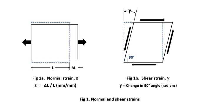
Fig. 1 Normal and shear strains. Source | Dan Adams
For starters, strain is the measure of a material’s deformation during loading. Normal strain 𝜀 is a measure of the elongation or contraction of a material in a particular direction during loading (Fig. 1a). Normal strain measurements are required for determining the modulus of elasticity E and Poisson’s ratio ν of a material. Additionally, shear strain γ is an angular deformation measurement defined as the change in a 90-degree angle at a point in the material during loading (Fig. 1b). Shear strain measurements are used in determining the shear modulus G. For use in calculating these stiffness properties, strain measurements are obtained during the initial portion of the test, before the material begins to yield or fracture. Standardized test methods provide detailed procedures indicating the range over which strain measurements are to be obtained. Additionally, a material’s limiting strain values, corresponding to yielding or ultimate failure, are often required. For PMCs, which typically experience a more brittle failure, the strain at failure is often obtained.
Currently, the two most common strain measurement methods are strain gages and extensometers. Strain gages are thin metallic foil grids permanently bonded to the specimen surface. As the strain-gaged specimen is loaded and undergoes strain, the electrical resistance of the strain gage changes. This change in resistance is measured using specialized conditioning electronics, and then converted to a strain value using a manufacturer-provided gage factor. Strain gages are designed to be highly sensitive to strains in the designated gage direction, and relatively insensitive to strains in other directions. They are commercially available in a variety of shapes and sizes.
When using strain gages with PMCs, attention must be given to two additional considerations. The first is the electrical resistance of the strain gage. Since strain gages are effectively precision resisters, the amount of heat produced depends on the electrical resistance of the strain gage (typically 120 or 350 ohms) and the excitation voltage used during operation. The effect of excessive heat generation is most noticeable when attempting to zero the strain gage output prior to testing; the strain reading will drift as the strain gage heats and expands the specimen locally. Therefore, the use of higher-resistance (350-ohm) strain gages coupled with reduced excitation levels is recommended when testing PMCs.
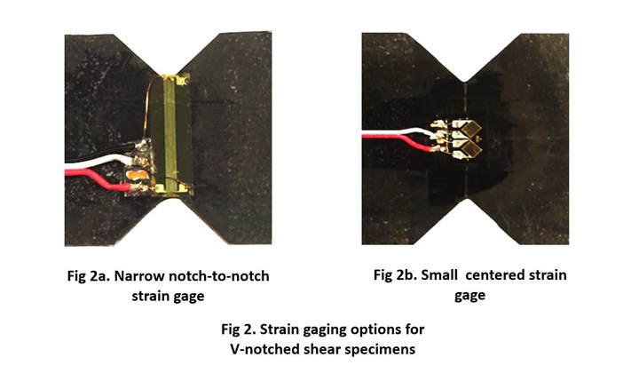
Fig 2. Strain gaging options for V-notched shear specimens. Source | Dan Adams
The second consideration when testing PMCs is the selection of a proper strain gage size and shape, which can be important when testing PMCs because of material-produced and specimen-produced strain variations. Material-produced strain variations are of concern when testing textile composites due to their periodic geometry and undulating fiber tows. As discussed in my July 2019 column, a sufficiently large strain gage is required to measure the average strain corresponding to the bulk material response. Additionally, specimen-produced strain variations are of concern when using the V-notched shear test methods for composites, ASTM D53791 and ASTM D70782. For accurate shear modulus measurement using these V-notched test specimens, either a narrow notch-to-notch strain gage must be placed between the notch tips (Fig. 2a) or a relatively small strain gage must be placed in the center of the test section where the average strain value occurs (Fig. 2b). Note that although strain gages cannot directly measure shear strain, normal strain measurements obtained in designated directions can be used to calculate shear strains using equations of strain transformation.3 For the V-notched shear test methods mentioned above, the shear strain γ is calculated by summing the magnitudes of the normal strains measured at +45° and -45° using the equation
In addition to material property determination, strain gages are also used to monitor specimen alignment during testing. For example, back-to-back strain gages on the front and back specimen surfaces are used during compression testing to check for bending and buckling during loading. In fact, the two ASTM compression test methods for PMCs, ASTM D34104 and D66415, require that back-to-back strain measurements be used to determine the percent bending when performing compression tests.
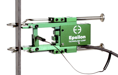
Fig. 3. Contacting extensometer for tension testing. Source | Epsilon Technology Corp.
In addition to strain gages, extensometers are also commonly used for strain measurement when testing. The most common type, contacting extensometers, usually contact the specimen using knife edges and are held in place with clips, springs or rubber bands (Fig. 3). Extensometers measure the average strain over a prescribed gage length, typically 25 millimeters. Although back-to-back extensometers are available for monitoring specimen bending, the short gage length (13 millimeters) commonly used in the compression test methods mentioned above makes the use of extensometers difficult. However, biaxial extensometers can be used for measuring the axial and transverse strains required for determining the modulus of elasticity E and Poisson’s ratio ν. Currently, however, there are no commercially available extensometers for use with the V-notched shear tests mentioned above to measure the shear modulus G of PMCs.
Unlike strain gages, extensometers are reusable, and require considerably less time and expense to install onto the specimen. However, they have a considerably higher initial cost and can be damaged when the specimen fails. Since high-energy specimen failures are common during mechanical testing of PMCs, the extensometer is often removed from the specimen prior to failure. This prevents damage to the extensometer, but also means that failure strain cannot be measured.
Two types of non-contacting extensometers are also available: laser-based extensometers and video extensometers. In laser extensometry, the specimen is illuminated using visible laser light, and a digital camera is used to record the change in distance between reflective markers placed on the specimen surface. Similarly, video extensometers use a high-resolution digital camera to accurately track the location of contrasting marks produced on the specimen surface to calculate strain. Both types of non-contacting extensometer can continue to measure strains up to specimen failure. Additionally, the range of permissible test temperatures can be extended significantly since the digital camera may be placed outside the environmental chamber and monitor the specimen through a window.
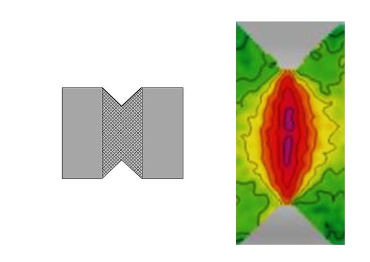
Fig. 4. Full-field strain contour plot of V-notched rail shear specimen from digital image correlation (DIC). Source | Dan Adams (left) and Instron Corp. (right)
Finally, in addition to strain gages and extensometers, digital image correlation (DIC) has become a highly promising method for strain measurement. Similar to video extensometry, DIC records the relative displacements of a random pattern of markers (speckle pattern) on the specimen surface using a high-resolution digital camera. In DIC, however, full-field strains are calculated within a region of interest, allowing for the generation of strain contour plots (Fig. 4) and subsequent strain averaging over any desired “gage area” of the specimen. The use of DIC appears promising for strain measurement in composites testing, and suitable calibration methods are in the process of being developed and standardized so that DIC may be used in standardized testing of PMCs and other materials. The development of a suitable calibration standard for DIC, analogous to that of ASTM E836 for extensometers, is currently in progress within ASTM International (West Conshohocken, Pa., U.S.).
References
1ASTM D5379/D5379 M-12, “Standard Test Method for Shear Properties of Composite Materials by the V-Notched Beam Method,” ASTM International (W. Conshohocken, PA, US), 2012 (first issued in 1993).
2ASTM D7078/D7078 M-12, “Standard Test Method for Shear Properties of Composite Materials by the V-Notched Rail Shear Method,” ASTM International (W. Conshohocken, PA, US), 2012 (first issued in 2005).
3“Strain Gage Rosettes: Selection, Application and Data Reduction,” Vishay Precision Group Tech Note TN-515, Document No. 11065, August 2014, online at www.vishaypg.com/docs/11065/tn-515.pdf
4ASTM D3410/D3410M-16, “Standard Test Method for Compressive Properties of Polymer Matrix Composite Materials with Unsupported Gage Section by Shear Loading,” ASTM International (W. Conshohocken, PA, US), 2016 (first issued in 1975).
5ASTM D6641/D6641M-16, “Standard Test Method for Compressive Properties of Polymer Matrix Composite Materials Using a Combined Loading Compression (CLC) Test Fixture,” ASTM International (W. Conshohocken, PA, US), 2016 (first issued in 2001).
6ASTM E83-16, “Standard Practice for Verification and Classification of Extensometer Systems,” ASTM International (W. Conshohocken, PA, US), 2016 (first issued in 1998).


Related Content

Testing to support composite bolted joint analysis
An overview of ASTM Standard Guide D8509, and its coupon-level mechanical testing of design properties for analyzing composite bolted joints.
Read More
Proving thermoplastic composites match carbon fiber/epoxy performance in road bikes
CDCQ, LxSim, Addcomp and Argon 18 collaborate to optimize a carbon fiber/PA6 bike seat post, democratizing AFP and demonstrating materials and process for future designs and production.
Read More
Carbon fiber/flax landing gear achieves 54% weight reduction via tailored layup optimization
Fuko’s Biogear showcases how strategic composite material distribution and natural fiber damping properties can lightweight and enhance critical aerospace structure performance.
Read More
Aurora reveals latest SPRINT X-Plane design concept
An Aurora and Boeing team advances its high-speed, vertical lift concept to the preliminary design phase, which features three lift fans, a more refined composite exterior and an uncrewed cockpit.
Read MoreRead Next

Polestar 5 takes aesthetics and circularity approach to biocomposite seatback design
The 2026 Polestar 5 expands the company’s use of sustainable materials design in the interior, including flax fiber/thermoplastic seatbacks that save 7 kilograms of weight and reduce overall plastics use.
Read More
Post Cure: CFRP mainframe, modern manufacturing techniques pioneer next-generation rigid airships
Advanced composites enable the revival of rigid airships in LTA Research's 400-foot-long Pathfinder 1.
Read More
Bonded fastening meets the digital factory
Automation and XR tools aim to scale adhesive fastening for composites at next-gen aerospace production rates.
Read More