


High-volume autocomposites production for the Audi A8
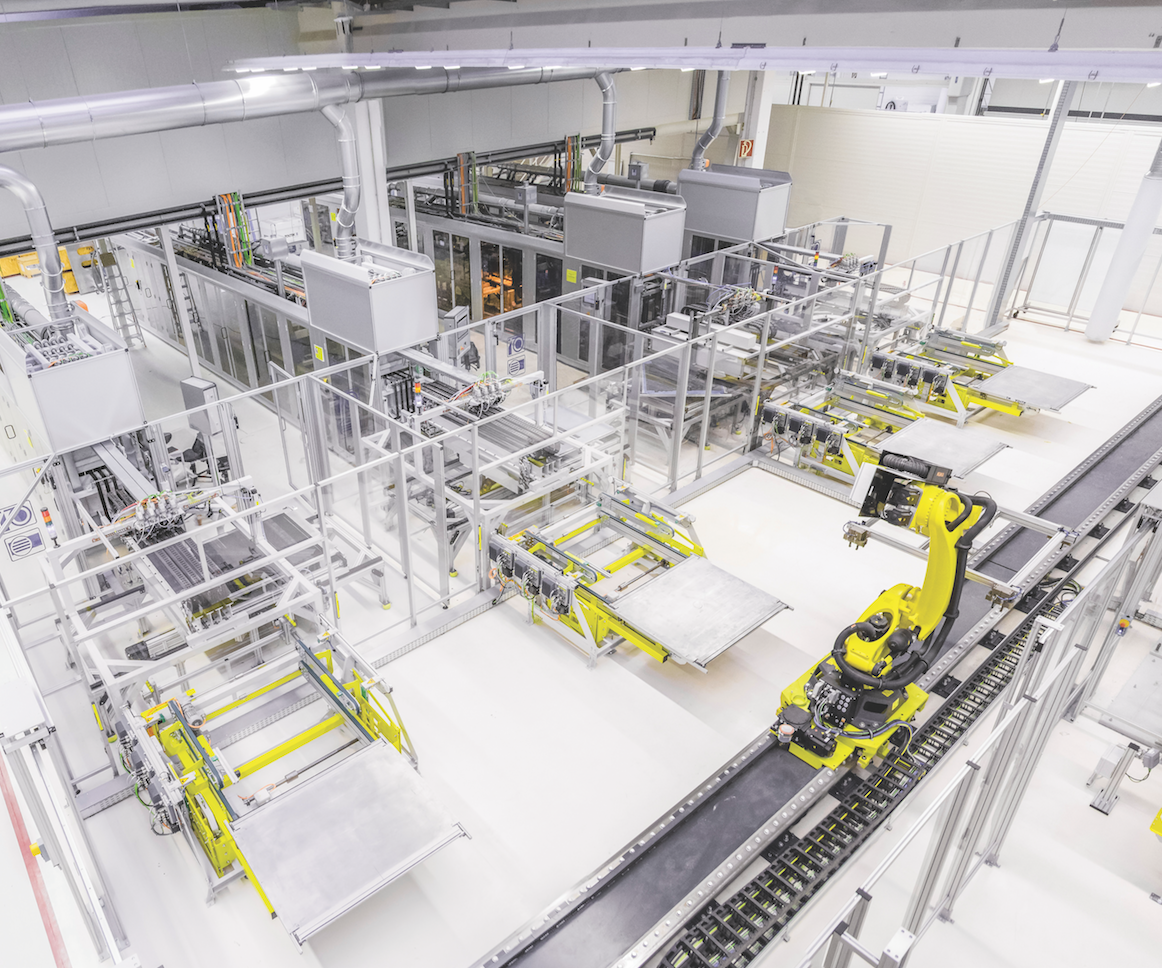
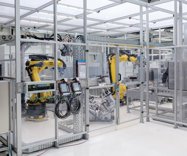
The highly automated processes envisioned by Voith Composites and Audi when they first partnered in 2011 has been realized. Four Voith Roving Applicator lines and a suite of fully automated forming, molding and assembly cells can produce hundreds of the rear wall modules per day.
Source | Voith Composites
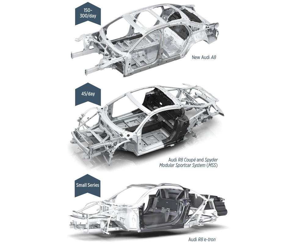
Fig. 1 From small series to high volume
Audi has optimized the production efficiency, cost and integral design of its CFRP rear wall as it evolved from the R8 e-tron, where the goal was maximized lightweighting, to the R8 MSS, the first step toward higher volumes in production, to the new A8, which demanded another level of industrialization.
Source | Audi AG
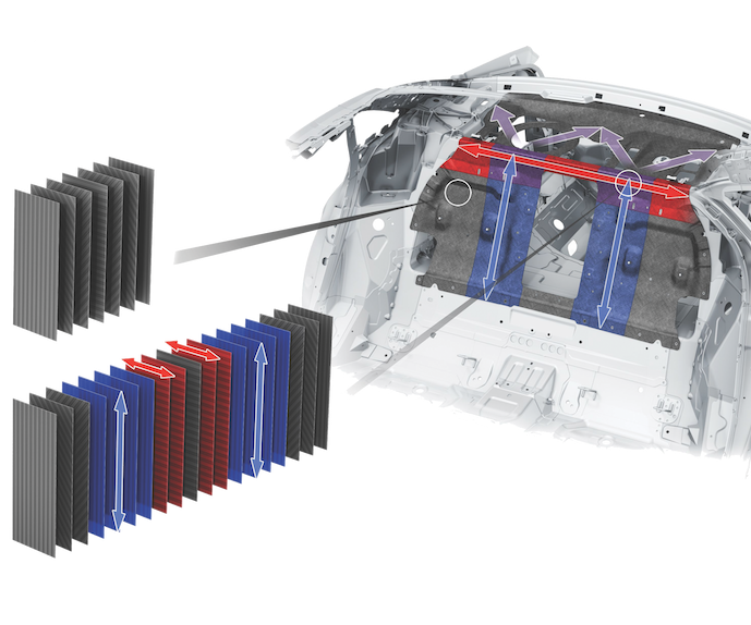
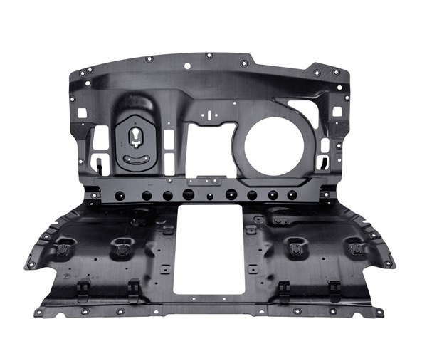
Fig. 2 UD tape provides design freedom and performance
The high performance of the Audi A8 CFRP rear wall was made possible by the design freedom of tailoring the orientation and placement of unidirectional tapes, realized in production by the Voith Roving Applicator. The composite laminate varies from six plies as a base to as many as 19 plies where additional reinforcement is needed.
Source | Audi AG

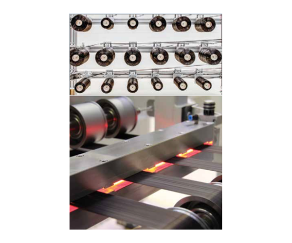
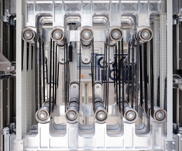
Fig. 3 The Voith Roving Applicator
Each automated Voith Roving Applicator line feeds fiber in from 12 bobbins of Zoltek P35 carbon fiber, spreads the 50K tow into four tapes, applies binder, consolidates the resulting tapes and then cuts, orients and stacks these tapes into tailored preforms for subsequent RTM processing.
Source | Voith Composites


At the onset of carbon fiber composites’ current advance into automotive applications, manufacturer BMW Group (Munich, Germany) seemed to stand apart. Initial work to accelerate resin transfer molding (RTM) for production of its M sport model’s roof led to establishment of a complete supply chain for carbon fiber-reinforced plastic (CFRP) parts on its i3 and i8 vehicles and then to all-new fabrication and assembly workcells for the multi-material Carbon Core body-in-white (BIW) on its 7 Series.
BMW committed to the i3 in 2009 to great fanfare, but that same year, Audi AG (Ingolstadt, Germany) established a technical center devoted to fiber-reinforced plastics. In 2011, Audi announced a partnership with Voith Composites (Garching, Germany) to develop and produce CFRP parts at high volume. The following year, it publicized the development of a CFRP-reinforced steel B-pillar, made using resin transfer molding (RTM), and its partnership with SOGEFI (Guyancourt, France) to commercialize composite coil suspension springs. In 2012, Audi also served as a founding partner for the MAI Carbon leading-edge cluster, which included BMW, Voith Composites, SGL Group (Wiesbaden, Germany) and others.


Most notably, Audi’s own narrative of CFRP development begins with its first-generation R8 sports car, released in 2006. It featured compartment covers for the convertible top as well as sideblades made by resin transfer molding (RTM). The company progressed from aesthetic exteriors and smaller structures to the Modular Sportscar System (MSS) in the Audi R8 e-tron. Although that electric supercar’s main structure comprised extruded aluminum beams joined by aluminum castings, all of the panels and in-fills were CFRP, including a trunk insert with corrugated crash structures that enabled the rear module to absorb five times as much energy as the metal frame.
The backbone of the MSS is its rear wall, which evolved from an initial concept in 2011 to the module that is currently produced for the non-electric R8 by SGL Technologies (previously BENTELER-SGL, Ort im Innkreis, Austria; see “Plant Tour: BENTELER SGL”). But Audi was already planning its next step: iterating the rear wall for use in its higher-volume A8 luxury sedan, with Voith Composites as its manufacturing partner.
Voith Composites is a 10-year old subsidiary of the multinational Voith GmbH & Co. KGaA, established in 1867. The parent company now fields 19,000 employees, has annual revenues of €4.2 billion (US$5.2 billion) and provides manufacturing equipment and technologies through four divisions: Voith Digital Solutions, Voith Hydro, Voith Paper and Voith Turbo. Voith Composites evolved from production of CFRP rolls used in papermaking to manufacturing automotive and industrial CFRP driveshafts/cardan shafts and flat laminates.
In 2011, Voith Composites began work on a highly automated CFRP process chain, aimed at producing the A8 rear wall. At its core was the Voith Roving Applicator (VRA), which, in a single line, spreads 35K carbon fiber tow from Zoltek (St. Louis, MO, US) into bindered unidirectional (UD) tape, which is then cut and stacked to form a tailored blank. The VRA was recognized with a JEC Innovation Award in 2017. It also established a robust base for subsequent preforming and molding operations. Auto category top honors were captured again for Voith Composites and Audi at JEC World 2018 for the completed VRA-based digital 4.0 production line used to manufacture the Audi A8 rear wall module. Working with resin supplier Dow Automotive (Auburn Hills, MI, US) and Zoltek, these partners not only developed the materials, process and integrated inline inspection systems necessary to manufacture high-performance CFRP parts at high-volume rates, but also created the full suite of essential computer-aided design/manufacturing (CAD/CAM) and simulation tools which are already being applied to develop future parts.
Efficiency-driven design evolution
“We began working with Audi early on,” says Dr. Jaromir Ufer, Voith Composites’ head of business development. The first priority was to develop the new A8 rear wall design, which would direct how the part should be manufactured.
“When we began the engineering for this production, we could not find off-the-shelf [software] products which had everything we needed,” explains Ufer. “So we brought together design tools like ABAQUS, but built our own material cards and developed our own simulation methods.” Audi had already identified reduced BIW weight and increased torsional stiffness as key objectives for the R8 rear wall design (see “Audi R8 seat wall: A prelude to production”). For the A8 module, an integral design was put forth to reduce the multi-component MSS assembly to a single, shaped CFRP panel with a small number of bonded and riveted attachments. This design drove development of a highly anisotropic laminate with localized load paths, which enables the finished part to provide 33% of the drive cell’s torsional stiffness at 50% of the weight vs. an assembly of three to five welded aluminum parts.
“The composite preform for the Audi A8 rear wall panel varies from a base of 6 plies up to 19 plies where local reinforcement is added — for example, where there are cut-outs or point loads, such as the child carrier restraint attachments,” explains Ufer (Fig 2).
Voith Roving Applicator
Ufer notes that development of this design and the VRA proceeded in tandem. “Only by having the design freedom that the VRA offers was the performance of the new A8 rear wall possible.” Also important was the fact that fiber supplier Zoltek made a 7-year price commitment to the program.
The VRA’s process begins with a creel of Zoltek’s PX 35 carbon fiber. Multiple bobbins of 50K tow are fed into each VRA line and spread to produce 50-mm wide tapes. Next, an epoxy-based binder is applied that will later react with the Dow VORAFORCE snap-cure epoxy matrix resin during resin transfer molding (RTM) of the composite part. A small amount of infrared (IR) heat is applied to melt the binder enough to hold the tape together through subsequent consolidation, cutting and stacking steps (Step 1).
Step 1: Zoltek 50K carbon fiber tow is fed into the Voith Roving Applicator (VRA), where it is first spread, then coated with epoxy-based binder and afterward IR-heated to partially melt the binder.
“This is a continuous process that is completely automated,” says Ufer. “If for some reason it is necessary to stop the line, the equipment reacts automatically. For example, the IR heater is immediately switched off and retracted to prevent damaging the tape from overheating. There are hundreds of such details in the equipment, and digital control enabling this technology.”
Step 2: The spread-tow tape is then consolidated as it proceeds through multiple rollers under tension.
After binder application, tape consolidation is achieved as it passes through multiple rollers under tension (Step 2). Ufer explains this also builds in a buffer for the line. “We have a unit that interrupts the continuous pull flow of the fiber, providing a transition to the pulse format of the tape cut-and-place mechanism.” This gantry-based mechanism cuts the tapes to tailored lengths and places them at specified angles from 0-360° onto a rotary table (Step 3). Each tailored stack, comprising 6 to 19 layers of tape, ranges in thickness from 1.5 to 3.7 mm, respectively.
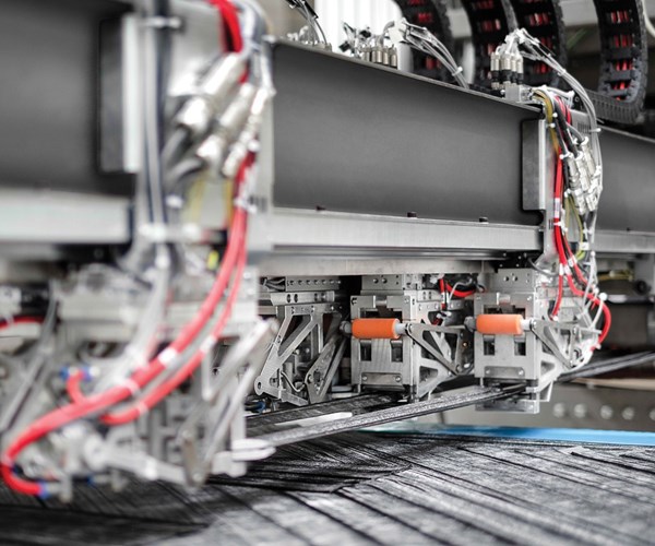
Step 3: The VRA then cuts the tape and places up to four pieces at a time on to a rotary table, tailoring both tape length and orientation angle within the laminate stack (e.g., 45°/90°/30°).
Voith has installed four VRA lines (see opening photo), and although each applies up to four 50-mm wide tapes at a time, Ufer points out, “the lines have a modular approach, so they could apply 10 or more tapes at a time. It depends on the part size and production rate.”
Automation includes quality inspection. Scans of the tapes and preforms are compared with a rejection algorithm. “The VRA’s 100% scanning of the tape ensures the right fiber distribution for the whole production line,” Ufer explains. “We also use thermography and laser sensors to check the preforms at designated areas.” The VRA then can react to any issues it detects. “If one tape is not correct,” he points out, “the VRA will cut out the deficient length and produce another to replace it.” A QR code is placed on the finished preform for traceability. (QR codes are preferred to radio frequency identification (RFID) tags because they reportedly better withstand the resin injection process.)
Forming, molding and assembly
The 2D stack exits the VRA and is shuttled into the production line’s forming, molding and assembly section. The first press into which it is placed, supplied by composites automation specialist FILL (Gurten, Austria), uses heat and pressure to shape the 2D tape stack into a 3D preform (Step 4). Ufer explains that because the preform varies in thickness and shape, the press can adapt the pressure applied as it stamp-forms separate regions of the preform clamped in the forming tool. ALPEX Technologies (Mils bei Hall, Austria) made the matched-steel RTM molds, based on a design provided by Voith Composites. “We developed the tooling and press process virtually,” says Ufer. “Although no actual test loop was required, we did validate and verify the simulation models on other shapes and parts prior to machining the A8 rear wall production tools. This simulation of the molding process ran right into real production, and helped to speed optimization.”
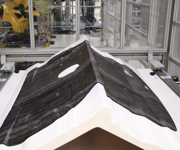
Step 4: The tape stack is shuttled into a press, where it is formed into the final 3D part shape.
The press holds for a few seconds to react the powder binder and set the shape, resulting in a stable preform that can resist fiber wash during resin injection. “The binder particles also function to hold the fibers apart for improved resin flow during RTM,” notes Ufer. “This is helpful because there is no stitching in the preform to aid in resin flow, so these binder particles act as micro flow channels.”
The shaped preform is next transferred by robot into an EiMa Maschinenbau GmbH (Frickenhausen, Germany) CNC cell, where an ultrasonic knife trims the outer final contour. It is then robotically placed into an RTM press (Step 5) supplied by ENGEL (Schwertberg, Austria). All robots in the line are supplied by KUKA Robotics (Augsburg, Germany).
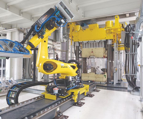
Step 5: The shaped preform is placed into a 350-kN press and molded, using ultra-RTM.
The RTM process used to mold the A8 rear wall is the same developed at the Audi Lightweight Center for the previous R8 rear wall, referred to as ultra-RTM. It enables molding of large parts using fast injection but low pressure. Compared to the 140 bar typical of HP-RTM, the in-mold resin-injection pressure during ultra-RTM of the Audi A8 rear wall is <15 bar, even less than that for the R8. As a result, instead of 2,500 kN of press force, only 350 kN is required. Therefore, a smaller, less-expensive press can be used to produce high-quality, high fiber-volume parts.
The VORAFORCE 5300 epoxy resin, a three-component system that includes mold release, cures in 90-120 seconds at 120°C and has a processing viscosity of 20 cps. For the A8 rear wall, a 1.3-kg resin shot is injected into the preform, followed by a 120-second cure.
The cured part is robotically demolded and loaded into a closed CNC milling cell for machining of cutouts. Next, the milled part is placed into an automated washing machine to clean off residual CFRP dust.
The washed rear wall is transferred into an assembly cell equipped with two robots. The first robot places the molded part into an automated riveting machine, which documents force applied during rivet installation. This is part of the manufacturing intelligence built into the overall process and is added to each part’s digital processing record (i.e., digital thread). The part is then moved into the bonding area and a second robot prepares areas for bonding, using an automated solvent wipe. The same robot then applies the fast-curing, two-component Dow BETAFORCE 9050M polyurethane structural adhesive (Step 6), which is compatible with the three-part epoxy. The part is next placed in an oven for a short adhesive cure cycle.
Step 6: BETAFORCE polyurethane adhesive is robotically applied for bonded attachments and then cured in a short oven cycle.
This production line maintains a 5-minute cycle time for the completed part and current demand for parts can be met in one or two 8-hr shifts. A 3D laser scanning device is used periodically to check the part’s 3D shape and measurements. Finished parts are then prepared for shipment to the Audi A8 final assembly line in Neckersalm, Germany, about 3 hours away by road (Step 7).
Step 7: The finished part is then prepared for shipment to the Audi A8 final assembly line.
Direct fiber placement = future flexibility
With all of the investment that has been made, it is surprising to learn that Voith Composites was not assured of this business, but indeed the company completed development and then participated in a competitive bid process to win production. “We were able to meet the target part cost defined by Audi, as well as quality and part performance requirements,” says Ufer. This was no small feat, considering that quite a few companies vied for the program.
Voith Composites has patented multiple parts of its process. “The VRA has demonstrated industrialization using direct fiber placement [DFP] of tapes, which reduces scrap as well as material used via a highly optimized layup,” says Ufer. It also uses the most cost-effective materials — untreated heavy-tow fiber and powder binder. Its second-generation process replaces powder binder with direct application of resin, eliminating more process steps. However, the company has developed other DFP processes, including the Voith Longfiber Preformer and Voith Prepreg Winding.
“We are setting new standards for carbon fiber parts for high-volume automotive serial production,” says Voith Composites managing director Dr. Lars Herbeck. “The smart factory we have established brings the automated production of CFRP components to a new level of efficiency and flexibility, including almost any shape as well as individual lot sizes.” This is, indeed, where the industry is headed.


.jpg;maxWidth=300;quality=90;format=webp)


Related Content

Plant tour: Joby Aviation, Marina, Calif., U.S.
As the advanced air mobility market begins to take shape, market leader Joby Aviation works to industrialize composites manufacturing for its first-generation, composites-intensive, all-electric air taxi.
Read More
Materials & Processes: Fabrication methods
There are numerous methods for fabricating composite components. Selection of a method for a particular part, therefore, will depend on the materials, the part design and end-use or application. Here's a guide to selection.
Read More
Large-format 3D printing enables toolless, rapid production for AUVs
Dive Technologies started by 3D printing prototypes of its composite autonomous underwater vehicles, but AM became the solution for customizable, toolless production.
Read More
Price, performance, protection: EV battery enclosures, Part 1
Composite technologies are growing in use as suppliers continue efforts to meet more demanding requirements for EV battery enclosures.
Read MoreRead Next

CW’s 2024 Top Shops survey offers new approach to benchmarking
Respondents that complete the survey by April 30, 2024, have the chance to be recognized as an honoree.
Read More
From the CW Archives: The tale of the thermoplastic cryotank
In 2006, guest columnist Bob Hartunian related the story of his efforts two decades prior, while at McDonnell Douglas, to develop a thermoplastic composite crytank for hydrogen storage. He learned a lot of lessons.
Read More
Composites end markets: Energy (2024)
Composites are used widely in oil/gas, wind and other renewable energy applications. Despite market challenges, growth potential and innovation for composites continue.
Read More