


Supporting a new supply chain
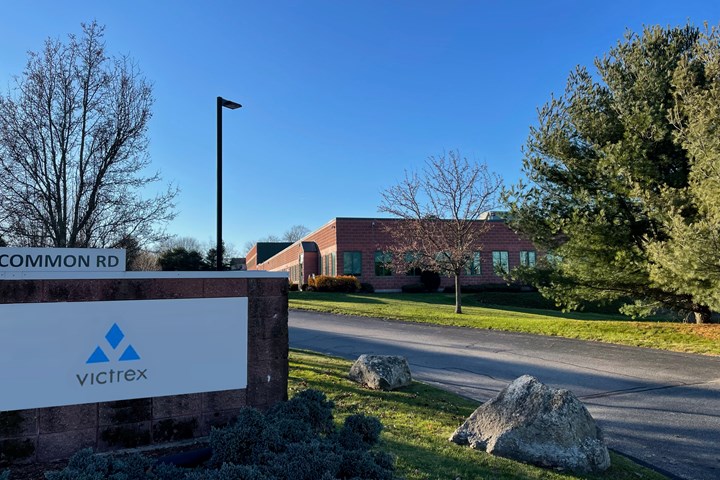
Victrex Composites Solutions is producing thermoplastic composite overmolded parts from its 5,000-square-meter production facility housed within a building it shares with long-time partner, Tri-Mack Plastics. Photo Credit: Victrex
When CW first discussed the overmolding process that Victrex (Cleveleys, Lancashire, U.K.) developed in 2015 (see “Overmolding expands PEEK’s range in composites”), it was revolutionary, opening a whole new category of “hybrid composites.” In the process, Victrex uses a continuous fiber-reinforced polyaryletherketone (PAEK) composite substrate, and then injection molds onto it a short fiber-reinforced polyetheretherketone (PEEK) compound. In the 2015 article, the result was a high-performance, hybrid composite bracket that was up to 60% lighter than a comparable metal component. The 305°C melt temperature of the Victrex low-melt PAEK (LMPAEK) polymer allows the substrate to melt at the surface when overmolded with the PEEK compound — which melts at 340°C — effectively creating a weld. The overmolding simultaneously functionalizes a composite part — for example, with reinforcing ribs or clips for LED lights — and allows it to be thinner, lighter and use less material than an unreinforced PEEK part.
In 2017, Victrex announced its investment in TxV AeroComposites (see “Victrex champions thermoplastic composites for aircraft industry”), a joint venture with customer and hybrid bracket co-developer Tri-Mack Plastics (Bristol, R.I., U.S.). That joint venture, which Victrex subsequently bought out and owns 100%, is now installed in a 5,000-square-meter building in Bristol. “The original idea was to create a sort of center of excellence where you could do all of the design and engineering, get tools built, make prototypes and, ultimately, produce commercial parts,” says Jonathan Sourkes, Victrex head of sales for aerospace. “Essentially, we’re here to make parts at industrial rates and to inspire other companies to do the same.”


De-risking thermoplastic composites production
CW’s tour of the Victrex Composites Solutions facility begins in the upstairs conference room, with a discussion about the transition from 2015 until now. When Victrex began production of its AE250 LMPAEK polymer, says Sourkes, “it saw the need for an entire ecosystem of product formats like fibers, films, powders and UD tapes, and also to perform research on how to process the polymer in composites and predict part performance in order to drive applications development. We have fully characterized the overmold-to-substrate bond, achieving a strength of up to 40 megapascals, which is twice that of an aerospace-grade adhesive bond and 50% better than the typical benchmark for thermoplastic composite welding.”
“Hybrid composites are gaining a lot more acceptance,” says Rob Mazzella, head of composites for Victrex, “but there’s still more to do in raising awareness on the possibilities of the technology to the supply chain. Our driver for this facility has always been capability for high-quality parts at high rates.”
“Our goal is to foster industry adoption and to de-risk and accelerate development for our customers,” says Sourkes. “That’s why we’re helping customers to develop hybrid parts [see sidebar below, “Hybrid composite engineering support”], and also selling composite laminates and inserts for others to overmold.” This facility was established, says Mazzella, “to support them in a way that requires moving beyond a center of excellence. This is why we’ve put in place equipment and a production footprint for high-rate PEEK and PAEK composites production. We have invested in automation that delivers industrial cycle times and repeatability.”
Hybrid parts, AAM and allowables
Hybrid part prototypes
Top left, clockwise: Monument bracket for regional aircraft, prototype advanced air mobility (AAM) part for Beta Technologies and prototype access door panel for a cargo aerial vehicle. Photo Credit: Ginger Gardiner, CW
Discussion now turns to an array of overmolded thermoplastic composite parts, including a 0.7- x 0.7- meter access door panel for a cargo aerial vehicle. “It’s made with 50 plies of UD tape and almost one kilogram of overmolding,” says Sourkes. “It also has a double curvature that forms a kind of pocket in the laminate which the overmolding fills.” The part was produced for the DARPA-funded RAPM project led by Boeing (see “Revolutionizing the composites cost paradigm, Part 2: Forming”). The part weighs 5 kilograms versus the previous aluminum part at almost 10 kilograms. “To get this shape from aluminum, they had to start with a 14- to 23-kilogram billet and CNC machine a lot of material away,” says Sourkes. “So, the buy-to-fly ratio was poor. The hybrid composite part has significantly less waste.”
Indeed, hybrid parts do really well where the buy-to-fly ratio needs to be improved. “Our materials and process offer sustainability benefits in terms of lightweighting, efficiency and CO2 reductions,” says Sourkes. “The hybrid composite access door has a cycle time under 10 minutes, whereas CNC machining it from aluminum would take all day. So, even though the CNC cost on a per-hour basis is lower than the composites process costs, we’re so much lower on process time that we end up with a better part cost.” Mazzella points out another part, a monument bracket for a regional aircraft that is still in development. “The buy-to-fly ratio was close to 10[:1], and we came in at 40% of the weight and 40% of the cost of the incumbent part,” says Sourkes.
Handing over a key-sized structure with a tear-shaped composite head and threaded metal bolt shank extending from the bottom, Mazzella notes, “This part is much smaller than what we normally work on, but it actually has not only a composite insert but also a metal bearing assembly that is overmolded. It’s the type of new application that we’re helping to innovate, because even saving a few grams per part adds up when hundreds of parts per aircraft are involved.”
The final part to be discussed is for the advanced air mobility (AAM) manufacturer, Beta Technologies (South Burlington, Vt., U.S.). “The application is targeting thousands of shipsets per year with multiple parts per shipset,” says Sourkes. “This is a glass fiber-reinforced PAEK part that we’re prototyping and is most of what is running in our equipment today.” Why hybrid composite? “To achieve the shape and not use any metal,” says Sourkes. “And the weight reduction is key because every gram matters in these battery-powered vehicles.” Even though discussion in the industry has been that AAM primary structures will use thermoset composites, Sourkes notes that “we’re hearing from AAM manufacturers that beyond 1,000 shipsets per year, they see the need for thermoplastics.” Traction has come quickly with AAM, says Mazzella. “There are certain parts of these aircraft where the requirements lend themselves really nicely to PEEK composites. We’re also starting to see the commercial aircraft OEMs and Tier suppliers start to dust off efforts that they were pushing fairly hard pre-COVID.”
Another issue for AAM, and an additional key part of the ecosystem that Victrex has been working on, is development of allowables databases. “NIAR [Wichita, Kan., U.S.] has published an NCAMP database for Toray Advanced Composites [Morgan Hill, Calif., U.S.] TC1225 carbon fiber/LMPAEK prepreg using static press molding,” says Sourkes. “Soon, we’ll publish our equivalency to that data using the shuttle press technology we have here. For test parts, we have a molding cycle of less than 15 minutes, but in practice, parts are typically molded in under 10 minutes. This is made possible because our shuttle press has an inherently quicker process time than a static press molding process.” While this NCAMP TC1225 database is based on Toray T700 carbon fiber, Victrex is working to get data published through NCAMP using AS4, IM7 and eventually AS7 carbon fibers. This will allow companies to get equivalency with their processes for a relatively small investment, says Sourkes. “We’ve invested significantly to democratize the data to support the industry.”
Flexible, industrial production
As we prepare to tour the production floor downstairs, Mazzella explains that Victrex’s process is based on automated tape laying (ATL) to create tailored blank preforms, followed by press consolidation, waterjet trimming, stamp-forming, CNC drilling and then overmolding. “Though we’d love to see Victrex materials in large primary structures,” he says, “we don’t aspire to produce those here.” What, then, is the targeted part size? “With ATL and a press, it doesn’t make sense to go much beyond 2 meters,” says Sourkes. “We could use other processes, but we chose ATL and stamping. By our analysis, if you can make the part in this way, the alternative technologies don't compete economically.”
“Our approach,” says Mazzella, “has been to put in place the most flexible facility capable of parts you can hold in one hand to parts spanning a meter or two as a hybrid. The programs we have now are feasible at an industrial scale, but if we’re going to start running 10,000 or 20,000 units per year of one part, then we’ll most likely install a purposely designed cell just for that.”
The tour, led by Sourkes and Victrex plant manager Kalon Lasater, began on the first floor beneath the offices, running from the front of the building to the back. The first area contains what are termed “dirty” processes, including CNC machining, a metal shop and an area for prototyping fixtures. A Haas Automation (Oxnard, Calif., U.S.) CNC cell is used to drill stamp-formed parts before overmolding. Just beyond it is an enclosed waterjet cell from Flow International (Kent, Wash., U.S.), used to trim consolidated laminates before stamp-forming.
As we pass through a door into the main production area, there is, notably, a lot of open space. “We installed equipment for what was ready for production today,” says Sourkes, “so we have a lot of space for growth.” Lasater notes that the floor layout was designed to allow for additional shuttle press stations as well as ATL, stamp-forming and overmolding lines. We walk past the shuttle press consolidation cell on the left and the robotic forming station opposite it on the right toward the enclosed ATL cell ahead on the left.
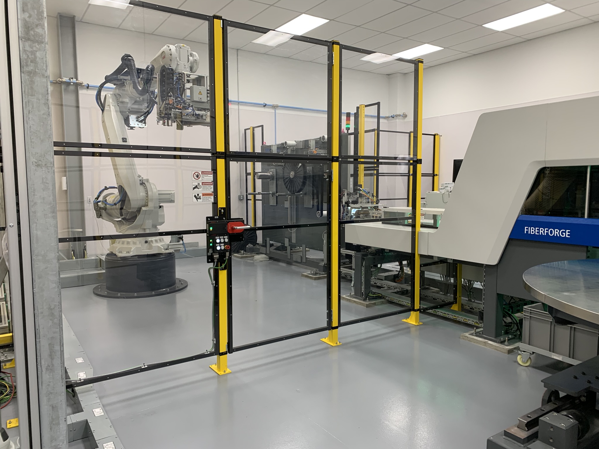
Automated tape laying (ATL) cell
Flexible, automated production. Robotic spool change-out and creel for automated tape laying (ATL) cell. Photo Credit: Ginger Gardiner, CW
Inside the ATL cell, a Dieffenbacher (Eppingen, Germany) Fiberforge 4.0 tailored blank line is producing carbon fiber/PAEK preforms for yet another AAM project. Standing in front of the Fiberforge, the operator control station is at left, and beyond that is an area for storing tape spools. Between the spool storage and the Fiberforge machine is a robot that picks up new spools and switches them out with depleted spools in the machine’s creel. This creel, which forms the left end of the Fiberforge machine, can feed up to four types of tapes, each with buffered unwind and tension control.
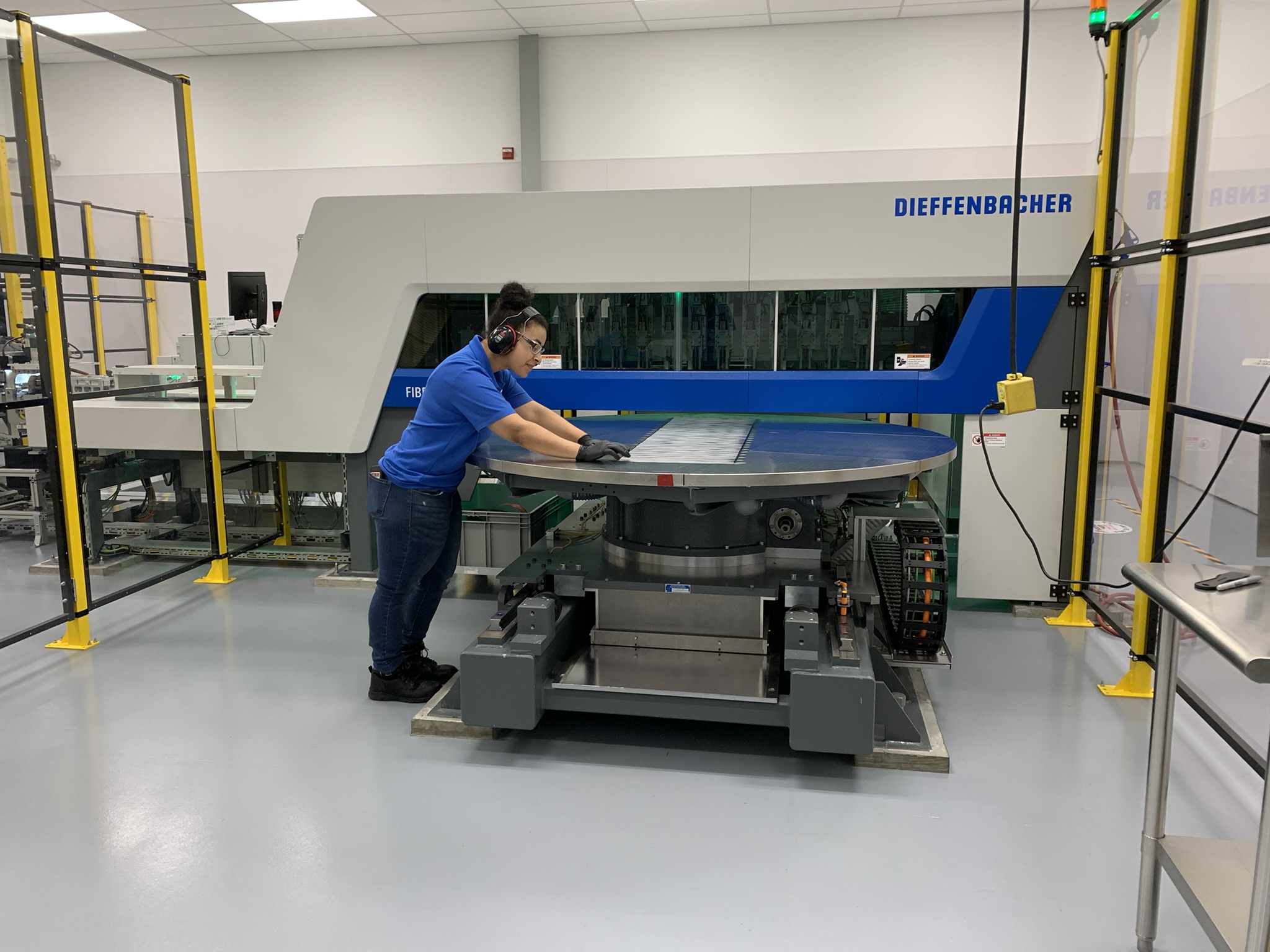
Fast preforms via ATL
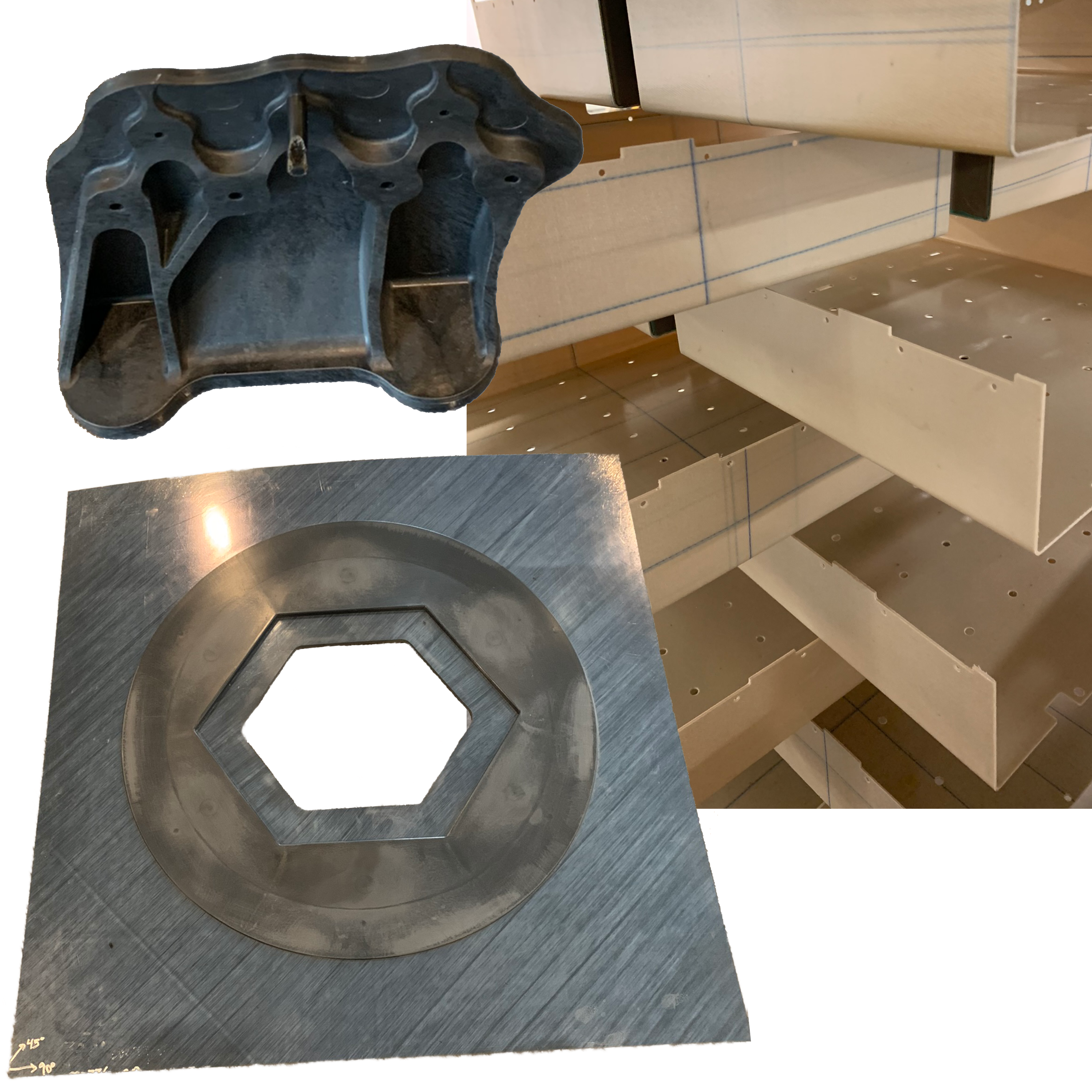
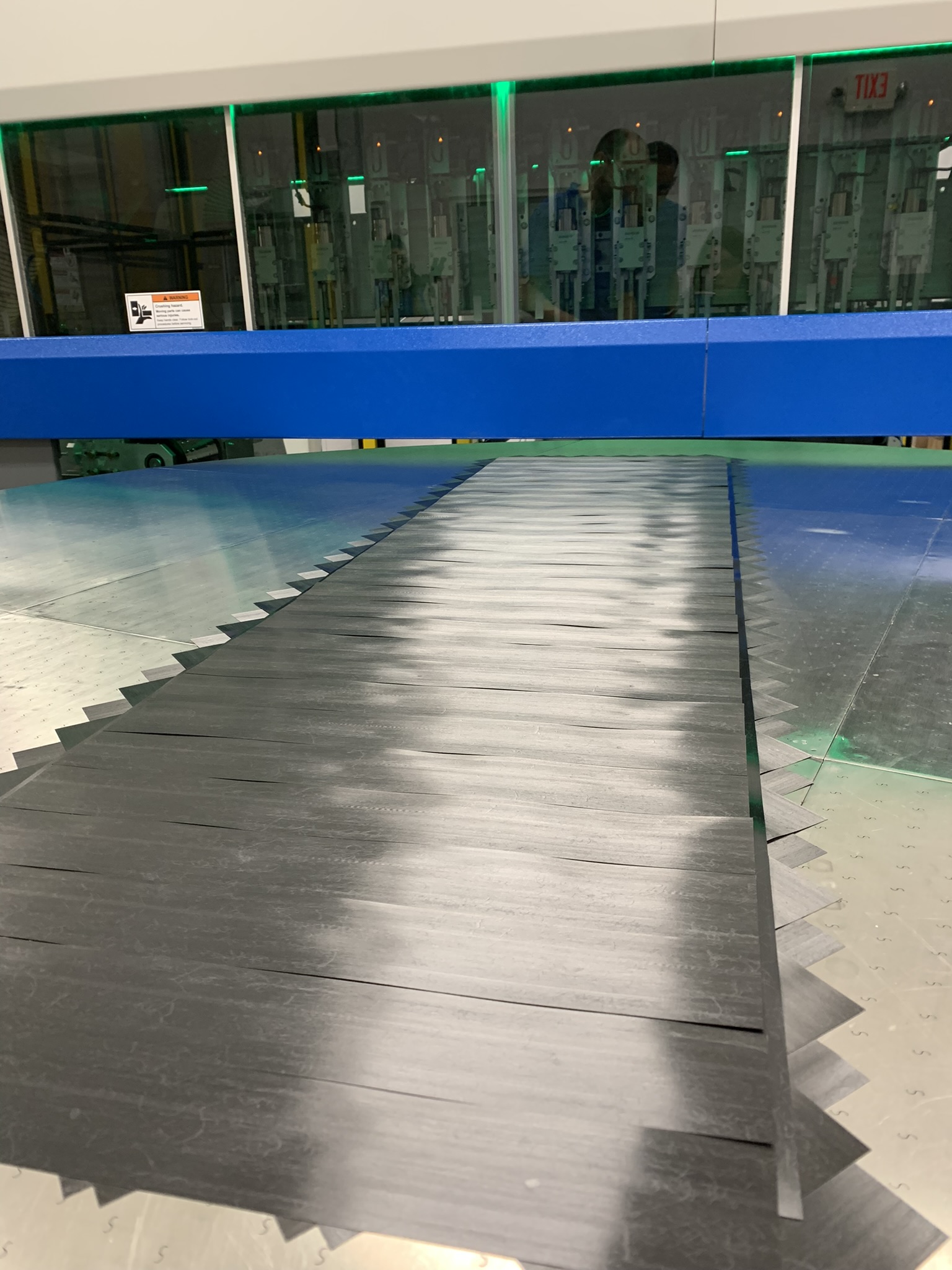
Rotary table (top) and multi-layer carbon fiber/PAEK preform (bottom). Photo Credit: Ginger Gardiner, CW
The next station to the right features two parallel rapid tape dispensers. These feed and cut tape with a <1 second cycle time at a maximum tape length of 2,000 millimeters. This includes subsequent ultrasonic spot welding to tack each ply to the one beneath. Alternatively, instead of one long tape, two shorter tapes can be placed simultaneously with the same sub-second speed.
Dieffenbacher claims a maximum deposition rate of 490 kilograms/hour. The ATL system works with all formulations of thermoplastic tapes, including Victrex PEEK and LMPAEK as well as glass and carbon fibers. Tape width can range from 50 to 165 millimeters and thickness from 0.1 to 0.4 millimeter. Cut tape length can range from 30 to 2,000 millimeters.
After cutting, the tapes are placed onto a 2-meter-diameter rotary table, fixed by a vacuum system and immediately tack-welded by a series of ultrasonic welding heads. Once the whole ply is completed, the table rotates and indexes to receive the next ply or translates quickly out from the tape layer toward the control station for inspection by the operator.
The process enables near-net shape layups and minimizes material waste. The ATL system allows layups with a small gap (e.g., 0.4 millimeter) between tapes. “The gaps close up as the tapes spread during consolidation,” notes Lasater. “We have placed up to 50 plies for that access panel we showed, but we haven’t hit our max yet.” Parts with 90 plies have been made by layering two ply stacks on top of each other. “This system is different from continuous compression molding [CCM],” he explains, “in that we don’t have to butt-weld tapes together to include off-axis plies. The table simply rotates, so we have a wide range of possible fiber angles, and weld locations are offset so that they aren’t in the same location for each ply.”
Weld locations are specified as part of production engineering design, as is the pressure for each weld and the shape, number and placement of tapes for each ply. Tailor-Gen is the software Dieffenbacher uses for its operator interface. “Imagine using Solidworks to design a laminate,” says Lasater. “You can predict run-time, material consumption and where each cut tape will be placed. It will also detect issues and reject the design, so that you’re not allowed to lay a bad course.”
Drying and consolidation
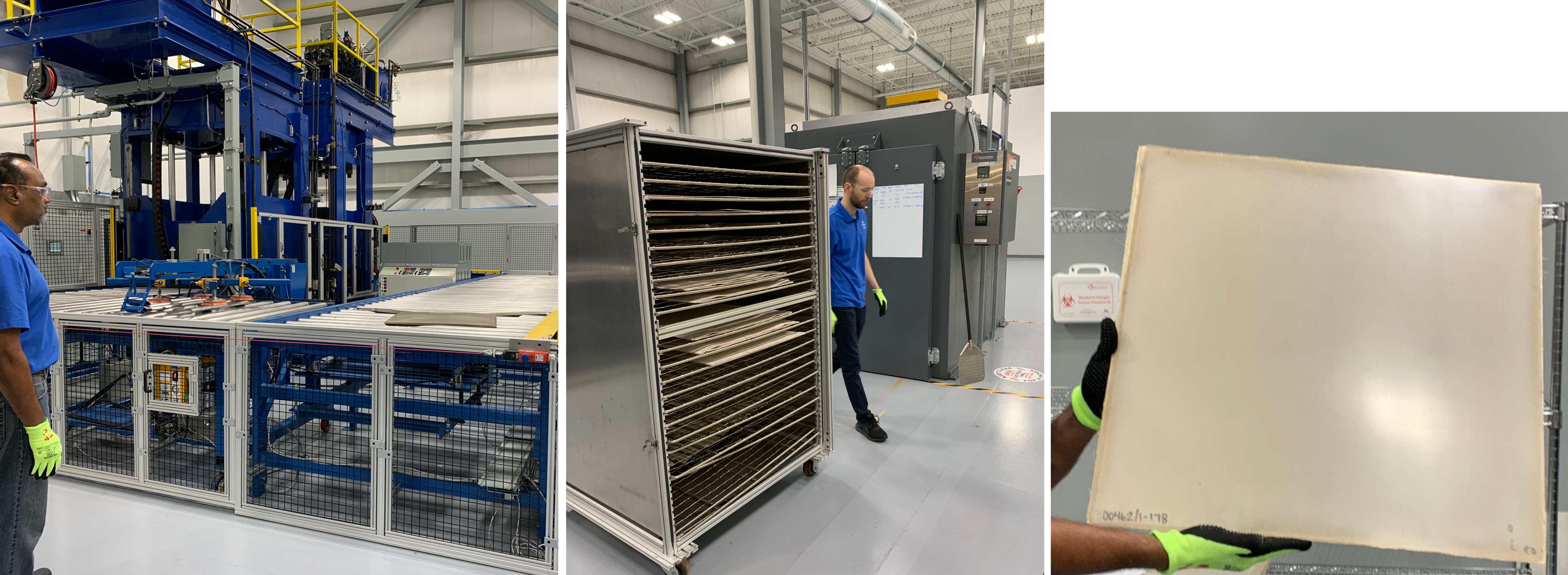
From the ATL cell, the tailored blanks are taken to a drying oven that sits adjacent to the shuttle press consolidation area. Even though PEEK and LMPAEK have <1% moisture absorption, finished tailored blanks are dried as a precautionary step to make sure no moisture exists that could cause porosity in the consolidated laminate. The oven drying cycle is typically 8 hours at 135°C, but depends on the thickness, says Lasater. The blanks are layered into wire racks within a large cart, which, when wheeled into the oven, enables cross-flow to dry each laminate. During our tour, the cart had ATL blanks on bottom and already-consolidated sheets on top. “We have two drying steps: one before consolidation and one after water jet cutting, before we put the consolidated blanks into the forming cell,” says Sourkes.
Drying and consolidation
ATL preforms are dried in an oven (middle) and then consolidated in the two-tower press (left). A consolidated laminate (right) inside a sheet metal transport tool is exiting the roller track and will be extracted using the robot with orange vacuum grippers. Photo Credit: Ginger Gardiner, CW
The consolidation cell measures roughly 6 x 9 meters, featuring a bespoke press with two towers, containing separately actuated platens, made by a U.S. supplier of traditional industrial equipment. The glass fiber/AE250 LMPAEK laminate used in the AAM part seen in the conference room is being consolidated using three sets of transport tools. Each 10-minute consolidation cycle comprises three simultaneous stages: (1) new blank moves into the first “hot” tower; (2) melted blank from first “hot” tower moves into second “cold” tower (which is still hot); (3) consolidated blank exits the second tower and moves around a deliberately sized track of metal rollers, the length calculated for sufficient cooling to develop the crystallinity needed for full mechanical properties. At the end of the track, the cell operator uses a robot with vacuum grippers to open the transport tool, and then, wearing heat-resistant gloves, removes the still-hot laminate and places it into a storage rack.
A single operator can run the whole cell, including loading and unloading the transport tools. The cell can run with a cycle time as low as three minutes, says Lasater, “in which case, we’d use four to five transport tools. These tools are size-specific but not part-specific and are made from low-cost sheet metal.”
“Normally, this type of press would only have two cylinders,” he continues, “but all of ours have four, which, when combined with advanced hydraulics and controls, achieves a very high level of parallelism during consolidation and also in our stamp-forming cell.” This is important to maintain flatness and precision in the laminates and finished parts.
“We also apply a Victrex LMPAEK film that aids in bonding during hybrid overmolding, which is part of the standard ply schedule for hybrid laminates,” Lasater explains, pointing to a box beneath the storage rack. Consolidated blanks are then sent next door to the waterjet cell for edge trimming and adding features prior to stamp-forming. As explained above, they are then dried again before proceeding to the stamp-forming cell.
Stamp-forming and overmolding
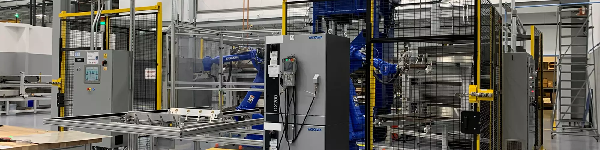
Robotic stamp-forming
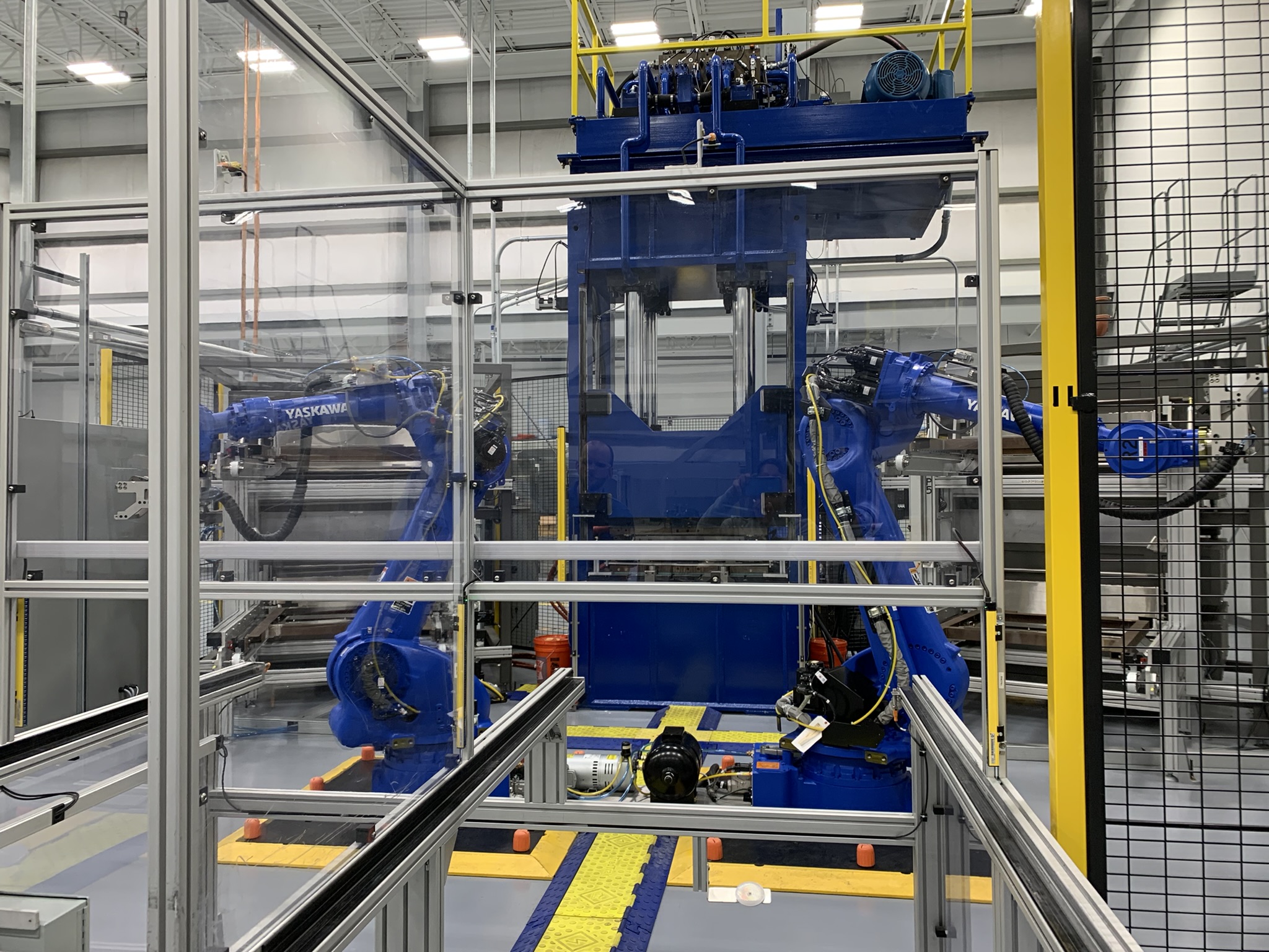
The rails in the foreground guide laminates fastened into tension frames (below) into and out of the stamp-forming cell featuring two robots and a 275-ton press in the background, flanked by upper and lower IR ovens on each side. Photo Credit: Ginger Gardiner, CW
This cell features a 275-ton press, made by the same supplier as the two-tower consolidation press. A stack of infrared (IR) ovens (Infrared Heating Technologies, Oak Ridge, Tenn. U.S.) is located on each side of the press for four ovens total. “This allows the cell to match the index pace of the press,” says Lasater. “As long as we have three to four fixtures for the consolidated sheets, we can have a laminate into the press each time it opens.”
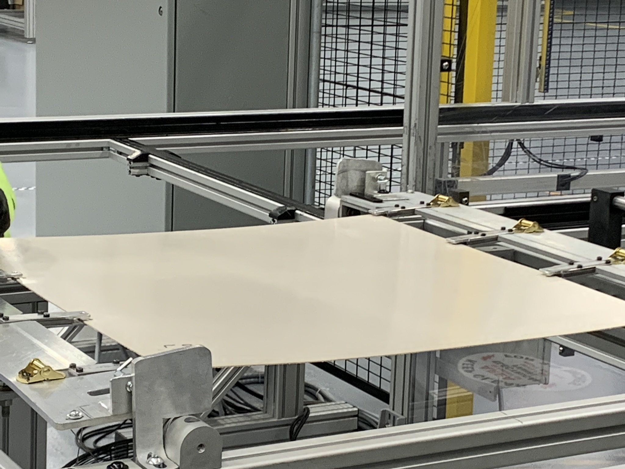
Precise tensioning for wrinkle-free parts
Consolidated thermoplastic composite laminates are fastened into frames specifically located and tensioned to allow forming without wrinkles. This laminate will be stamp-formed into the parts shown stacked on p. XX. Photo Credit: Ginger Gardiner, CW
The fixtures are metal frames configured precisely to hold the consolidated laminate and enable forming the desired 3D geometry without wrinkles. Sourkes notes that the forming process is typically optimized during design using forming simulation software like AniForm (AniForm Engineering, Enschede, Netherlands). “Deeper-draw, complex geometries require extensive simulation to arrive at an optimized fixture design,” he adds. “That’s how we also derive the optimal press-closing speeds and pressure profiles, which are key parameters.”
The clamping fixture sits on a set of rails that feeds into the stamp-forming cell, which is also run by one operator. After fastening the laminate into the forming fixture, the operator pushes a button and the fixture moves into the cell where one of two Yaskawa (Miamisburg, Ohio, U.S.) robots picks up the fixture and places it in the top left IR oven. After a brief preheat cycle, the IR oven opens and the robot quickly transfers the fixture into the forming press, which immediately closes and begins the 2-minute press cycle for this part. The time and temperature of the IR oven and press follow a pre-programmed recipe optimized during the part design process. “We control both temperature and pressure and know where the preform is located within the press every time,” says Sourkes. Once the press cycle is complete, the robot removes the fixture from the press and returns it to the rail system where the operator removes it and prepares another laminate.
Injection overmolding
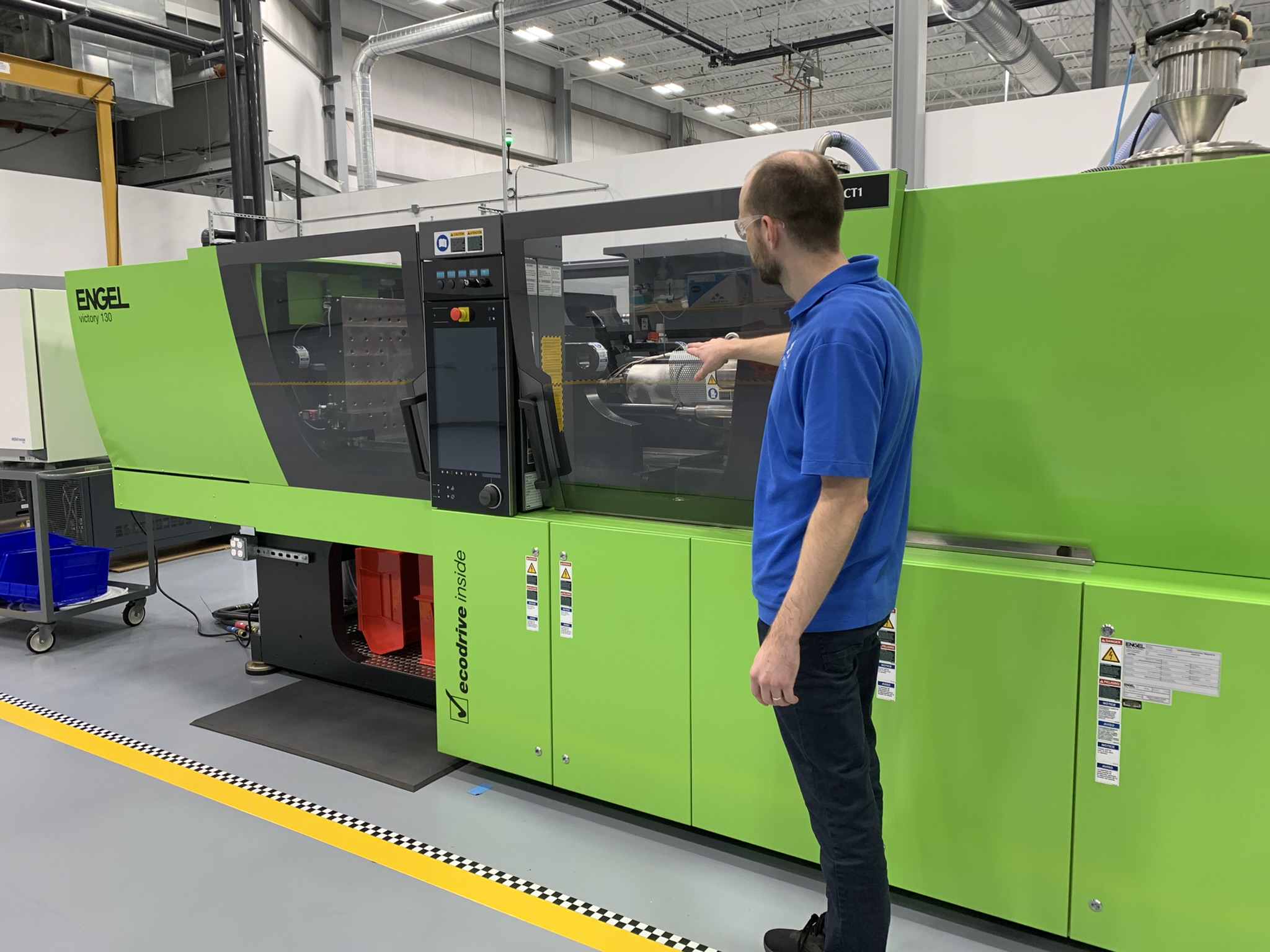
The Engel Victory 130 injection molding cell can overmold composite substrates up to 1 square meter. More cells will be added as programs complete qualification over the next five years. Photo Credit: Ginger Gardiner, CW
After stamp-forming and CNC drilling, parts are transferred to the overmolding cell, located directly across from the ATL cell. Situated within a large walled production area is a single Engel (Schwertberg, Austria) Victory 130 injection molding machine that has been tailored for the high temperatures required for PEEK and PAEK. “We also need a machine that can take large substrates up to 2 meters wide or long,” says Lasater, “and overmold these using shots of plastic that are 1 kilogram or less, which is small compared to typical plastics injection molding. And we need significant force to resist the backpressure of overmolding, otherwise the molding compound would flash out. That’s why these machines tend to be high tonnage for the shot size.”
From the overmolding area, parts are transferred to the rear of the building and prepared for shipping . As we walk back toward the front of the building, we turn left just before the stamp-forming cell and enter a lab set behind it. This analysis lab is where part samples are checked for crystallinity using a differential scanning calorimeter (DSC). “We use this for validating process parameters,” says Lasater, “to confirm our cooling cycle, for example. We then use our process control to make sure every part conforms to the specification.” In the opposite corner is a Hexagon Manufacturing Intelligence coordinate measuring machine (CMM), used to validate geometry precision before finalizing process specs.
Five years forward
As the tour concludes, I ask the team to describe this production floor in five years. “We’ll have purpose-built production cells,” says Sourkes. “We have very flexible equipment on the floor right now, but installation of new cells will be optimized for a family of parts, most likely for AAM. In five years, we’ll also have hybrid processes qualified with commercial aerospace OEMs, which will open further applications for us and other parts manufacturers.”
“Those qualifications are investments and programs that are already ongoing,” adds Mazzella. “Some will come online in closer to two years, but by five years, everything we’ve got active now should be at TRL [technology readiness level] 9.” Sourkes notes that four to five NCAMP databases for thermoplastic composites should also be completed, “which will allow us to help our customers get parts certified with the FAA and EASA. Right now, everything is point design, but in five years, it will be much easier. And that’s really why this dedicated composites solutions facility exists — to take that design and development capability and polyketone expertise, along with the process and production lessons that we’ve learned here, and apply this to convert aluminum, titanium or thermoset composites designs into thermoplastic hybrid composites parts that can be produced at an industrial scale.”


.jpg;maxWidth=300;quality=90;format=webp)


Related Content

Materials & Processes: Fibers for composites
The structural properties of composite materials are derived primarily from the fiber reinforcement. Fiber types, their manufacture, their uses and the end-market applications in which they find most use are described.
Read More
Cryo-compressed hydrogen, the best solution for storage and refueling stations?
Cryomotive’s CRYOGAS solution claims the highest storage density, lowest refueling cost and widest operating range without H2 losses while using one-fifth the carbon fiber required in compressed gas tanks.
Read More
Plant tour: Joby Aviation, Marina, Calif., U.S.
As the advanced air mobility market begins to take shape, market leader Joby Aviation works to industrialize composites manufacturing for its first-generation, composites-intensive, all-electric air taxi.
Read More
One-piece, one-shot, 17-meter wing spar for high-rate aircraft manufacture
GKN Aerospace has spent the last five years developing materials strategies and resin transfer molding (RTM) for an aircraft trailing edge wing spar for the Airbus Wing of Tomorrow program.
Read MoreRead Next

Overmolding expands PEEK’s range in composites
A new polymer and a hybrid process enable production of complex, high-load-capable, fiber-reinforced brackets and clips in minutes.
Read More
Revolutionizing the composites cost paradigm, Part 2: Forming
Boeing-led parts trials explore infusion, compression molding and thermoplastics, offering lessons and supply chain options to better compete with aluminum.
Read More
Overmolding as enabler for composites, aerospace to automotive
CCP Gransden can make 50 to 100,000 parts/yr economically viable using PEEK, PPS, PEI or PA.
Read More